Table of Contents
Advertisement
Advertisement
Table of Contents

Summary of Contents for Sunwave CrossFire HP
- Page 1 CrossFire CrossFire CrossFire CrossFire HP User Manual Revision 05...
-
Page 2: Table Of Contents
CrossFire HP – All-Digital Transport System User Guide Table Table Table of of of of Contents Contents Contents Table Contents 0. Preface....................................10 0.1. Safety Instructions..............................10 0.2. Warning..................................11 0.3. Electrostatic Protection............................. 13 0.4. Standards...................................13 0.5. Abbreviations................................13 1. System Overview.................................. 15 1.1. - Page 3 CrossFire HP – All-Digital Transport System User Guide 3.3. AU Back Panel................................35 3.4. AU Active Combiner..............................36 3.5. Indicator Descriptions..............................36 3.6. Master / Slave AU Selection............................37 3.7. OMT Parameters, Alarms and Commands for the AU....................38 3.7.1. AU User and Network Parameters........................38 3.7.2.
- Page 4 CrossFire HP – All-Digital Transport System User Guide 5.4.1. RU User Parameters............................52 5.4.2. RU Alarms............................... 52 5.4.3. RU System Info..............................53 5.4.4. RU Band Config...............................53 5.4.5. RU Digital Info..............................53 5.4.6. RU Actual Gain..............................54 5.4.7. RU Engineering Information........................... 54 5.4.8. RU Command..............................55 6.
- Page 5 CrossFire HP – All-Digital Transport System User Guide 6.4.5. Standby battery connection........................... 72 6.5. WLAN Access (Wi-Fi)..............................72 7. System Debugging Setup..............................74 7.1. Network Management System Setup for SNMP....................... 75 7.2. Channel Properties Configuration..........................76 7.3. Channel Gain Adjustment............................78 7.4.
- Page 6 CrossFire HP – All-Digital Transport System User Guide Table Table Table of of of of Figures Figures Figures Table Figures Figure 1- 1 CrossFire Operating Fundamentals........................15 Figure 1- 2 Typical System Framework for the CrossFire......................16 Figure 1- 3 Networking Layout..............................17 Figure 2- 1 Setting up a Wired Connection to the OMT on the Master AU................19...
- Page 7 CrossFire HP – All-Digital Transport System User Guide Figure 4- 2 Front Panel of the EU............................. 44 Figure 4- 3 Back Panel of the EU...............................45 Figure 5- 1 Physical Appearance of the RU..........................49 Figure 5- 2 Front Panel of the RU............................. 50 Figure 6- 1 Wall Mounting Installation of an EU........................58...
- Page 8 CrossFire HP – All-Digital Transport System User Guide Figure 8- 1 Checking Software Package Version........................82 Figure 8- 2 Software Upgrade Step 1............................83 Figure 8- 3 Software Upgrade Step 2............................83 Figure 8- 4 Software Upgrade Step 3............................83 Figure 8- 5 Setting up Remote Upgrade via FTP........................84 Figure 8- 6 Remote Upgrade using an NMS..........................
- Page 9 CrossFire HP – All-Digital Transport System User Guide List List List of of of of Changes Changes Changes List Changes Ed Ed Ed Ed Author Author Author Author A A A A pprover pprover pprover pprover Remarks Remarks Remarks Remarks...
-
Page 10: Preface
CrossFire HP – All-Digital Transport System User Guide High High Power- Power- CrossFire CrossFire User User Guide Guide High High Power- Power-CrossFire CrossFire User User Guide Guide 0. 0. 0. 0. Preface Preface Preface Preface 0.1. 0.1. Safety Safety Instructions Instructions 0.1. -
Page 11: Warning
CrossFire HP – All-Digital Transport System User Guide installation, otherwise the device temperature may rise and affect the service life of the device. 9. Replacing the Power Amplifier (PA) module and duplexer module onsite is permitted. Power off the device before replacing. - Page 12 CrossFire HP – All-Digital Transport System User Guide WARNING: WARNING: WARNING: WARNING: Changes or modifications to this equipment not expressly approved by SUNWAVE could void the user's authority to operate the equipment. WARNING: WARNING: WARNING: WARNING: This is NOT a CONSUMER device. It is designed for installation by FCC LICENSEES and QUALIFIED INSTALLERS.
-
Page 13: Electrostatic Protection
CrossFire HP – All-Digital Transport System User Guide appropriate means. Awareness of the potential for RF exposure in a workplace or similar environment can be provided through specific training as part of a RF safety program. NOTE: NOTE: NOTE: NOTE: This device complies with Industry Canada license-exempt RSS standard(s). Operation is subject to the following two conditions: (1) this device may not cause interference, and (2) this device must accept any interference, including interference that may cause undesired operation of the device. - Page 14 CrossFire HP – All-Digital Transport System User Guide Expansion Unit FPGA Field Programmable Gate Array iDAS Integrated Distributed Antenna System Global System for Mobile Communication Interface Processing Module Long Term Evolution Network Management System Operations and Maintenance Center Operations and Maintenance Terminal...
-
Page 15: System Overview
CrossFire HP – All-Digital Transport System User Guide 1. 1. 1. 1. System System System System Overview Overview Overview Overview 1.1. 1.1. Overview Overview 1.1. 1.1. Overview Overview The CrossFire system includes the Access Unit (AU), Expansion Unit (EU) and Remote Unit (RU). -
Page 16: Technical Specifications
CrossFire HP – All-Digital Transport System User Guide E E E E U U U U RU1 1 1 1 TDD LTE TDD LTE TDD LTE TDD LTE MIMO MIMO MIMO MIMO TDD LTE TDD LTE TDD LTE TDD LTE... -
Page 17: Networking Layout
CrossFire HP – All-Digital Transport System User Guide F ib er R U1 WLAN Sw itc h WLAN Sw itc h F ib er R U2 Fibe r Fibe r E U4 E U1 R U3 F ib er WLAN Sw itc h... - Page 18 CrossFire HP – All-Digital Transport System User Guide E U-1 E U-2 E U-3 E U-4 Fib e r O P1/A U B a n d1 s la v e master s la v e master s la v e...
-
Page 19: Operations And Maintenance Terminal
CrossFire HP – All-Digital Transport System User Guide 2. 2. 2. 2. Operations Operations Operations Operations and and Maintenance Maintenance Maintenance Maintenance Terminal Terminal Terminal Terminal 2.1. 2.1. Introduction Introduction Introduction to to to to the 2.1. 2.1. Introduction the OMT The Operations and Maintenance Terminal (OMT) software runs on all of the devices in the CrossFire system. - Page 20 CrossFire HP – All-Digital Transport System User Guide Network Network Connections Connections Click Network Network Connections Connections Click Local Local Local Local Area Area Area Area Connection Connection Connection Connection Properties Properties Properties Properties TCP/IP Properties a. Click TCP/IP TCP/IP...
-
Page 21: Wired Access To The Omt On The Slave Au, Eu And Ru
CrossFire HP – All-Digital Transport System User Guide Figure Figure Figure Figure 2 2 2 2 - - - - 2 2 2 2 Web Web Browser Browser Browser Browser OMT OMT Connection Connection Connection Connection for for Wired Wired... - Page 22 CrossFire HP – All-Digital Transport System User Guide Figure Figure Figure Figure 2 2 2 2 - - - - 3 3 3 3 Wired Wired Wired Wired access access access access to to to to WebOMT WebOMT WebOMT WebOMT on...
-
Page 23: Wireless Access (For Au And Eu)
CrossFire HP – All-Digital Transport System User Guide 2.2.3. Wireless Access (for 2.2.3. 2.2.3. 2.2.3. Wireless Wireless Wireless Access Access Access (for (for (for AU AU and and EU) Figure 2- 4 shows the equipment required for wireless access to the OMT. - Page 24 CrossFire HP – All-Digital Transport System User Guide 6. Open a browser window and enter the assigned default gateway into the navigation bar. This will access the WebOMT page. Figure 2- 9 shows an example using 12.7.1.1 as the default gateway.
- Page 25 CrossFire HP – All-Digital Transport System User Guide Figure Figure Figure 2 2 2 2 - - - - 6 6 6 6 Viewing Viewing Viewing Available Available Wireless Wireless Networks Networks Figure Viewing the the Available Available Wireless Wireless Networks...
-
Page 26: Usb Access
CrossFire HP – All-Digital Transport System User Guide Figure Figure Figure Figure 2 2 2 2 - - - - 8 8 8 8 Checking Checking Checking Checking the the Wireless Wireless Wireless Wireless Network Network Network Network Status Status... -
Page 27: Omt Display
CrossFire HP – All-Digital Transport System User Guide 2.3. Display 2.3. 2.3. 2.3. OMT OMT Display Display Display 2.3.1. 2.3.1. 2.3.1. 2.3.1. Login Login Login Login Figure 2- 10 shows the login page and default username & password. See Section 2.3.3 for the details about user management. - Page 28 Info: Includes “Station ID”, “Device ID”, “Dev Type” and “Dev Name” information. 2. ScreenShot ScreenShot ScreenShot ScreenShot: Used for saving the current parameter information and device operating status. When SUNWAVE assistance is required to troubleshoot the system, send the “ScreenShot” file to the SUNWAVE technicians. To use the ScreenShot ScreenShot ScreenShot ScreenShot function, follow the procedure below: a) Select the page that you want to save.
- Page 29 CrossFire HP – All-Digital Transport System User Guide Configuration Configuration 6 6 6 6 d) Click the Configuration Configuration button. See in Figure 2- 11. e) Click the Download Download Download Download shortcut icon to download the screen shot file. Check the filename and date to ensure that the correct file has been selected.
-
Page 30: Users Management
CrossFire HP – All-Digital Transport System User Guide file. Upgrading Upgrading Upgrading Upgrading: Used to upgrade the software. See Section 8 for details. Register Register Register Register: This function is not relevant for maintenance activities. Configuration Configuration Configuration Configuration: See Section 7.5 for details. - Page 31 CrossFire HP – All-Digital Transport System User Guide Enter the password and confirm. See 2 2 2 2 in the Figure 2- 15. Click Add Add user user user user button. Figure Figure Figure Figure 2 2 2 2 - - - - 15 15 15 15 Add...
-
Page 32: Displaying The System Topology
CrossFire HP – All-Digital Transport System User Guide Password Password Click Password Password button. Figure Figure Figure 2 2 2 2 - - - - 17 17 17 17 Change Change Change Password Password Figure Change Password Password 2.3.4. 2.3.4. - Page 33 CrossFire HP – All-Digital Transport System User Guide Figure Figure Figure 2 2 2 2 - - - - 18 18 18 18 Displaying Displaying Displaying System System Topology Topology Figure Displaying the the System System Topology Topology Devices in the topology have two colors —green and red: •...
-
Page 34: Au Instructions
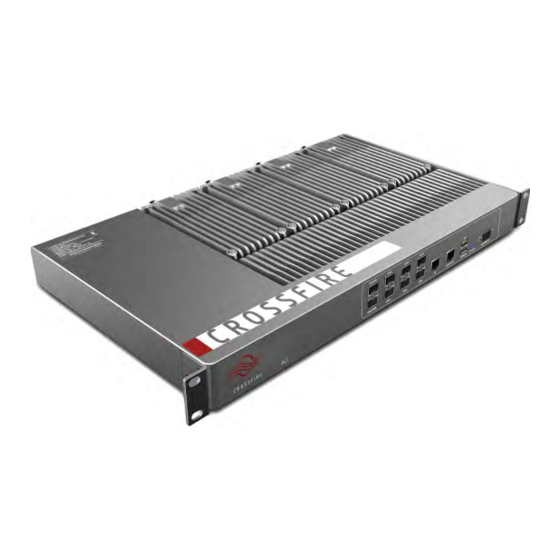
CrossFire HP – All-Digital Transport System User Guide 3. 3. 3. 3. AU AU Instructions Instructions Instructions Instructions 3.1. 3.1. Physical Physical Appearance Appearance 3.1. 3.1. AU AU Physical Physical Appearance Appearance Figure 3- 1 shows a photograph of the AU component of the CrossFire. -
Page 35: Au Back Panel
CrossFire HP – All-Digital Transport System User Guide Interface Interface Name Name Description Description Interface Interface Name Name Description Description Connects Slave AU2 OP1/AU For Master AU: connects EU/RU For Slave AU: connects Master AU Connects EU/RU Connects EU/RU Connects EU/RU... -
Page 36: Au Active Combiner
CrossFire HP – All-Digital Transport System User Guide 3.4. Active Combiner 3.4. 3.4. 3.4. AU AU Active Active Active Combiner Combiner Combiner Figure 3- 4 shows a schematic of the AU Active Combiner. Figure Figure Figure 3 3 3 3 - - - - 4 4 4 4 AU... -
Page 37: Master / Slave Au Selection
CrossFire HP – All-Digital Transport System User Guide In Figure 3- 2, “10 10 10 10” points to the STATUS STATUS STATUS STATUS indicator on the front panel of the AU. Table 4 lists the indicator’s behaviors and their meaning. -
Page 38: Omt Parameters, Alarms And Commands For The Au
CrossFire HP – All-Digital Transport System User Guide Figure Figure Figure Figure 3 3 3 3 - - - - 6 6 6 6 Master Master Master Master / / / / Slave Slave Slave Slave AU AU Selection Selection... - Page 39 CrossFire HP – All-Digital Transport System User Guide Table Table Table 5 5 5 5 Device Device Information Information Table AU Device Device Information Information Parameter Parameter Description Description RD/RW RD/RW Parameter Parameter Description Description RD/RW RD/RW Vendor Name Name to distinguish different manufacturers...
- Page 40 CrossFire HP – All-Digital Transport System User Guide Table Table Table 6 6 6 6 Network Network Management Management (TCP/IP (TCP/IP protocol) protocol) Table AU Network Network Management Management (TCP/IP (TCP/IP protocol) protocol) Parameter Parameter Description Description RD/RW RD/RW Parameter...
-
Page 41: Au Alarms
CrossFire HP – All-Digital Transport System User Guide Parameter Parameter Description Description RD/RW RD/RW Parameter Parameter Description Description RD/RW RD/RW FTP Username Username for device to log into FTP Server FTP Password Password for device to log into FTP Server... -
Page 42: Au Band Config
CrossFire HP – All-Digital Transport System User Guide Table Table Table 10 10 10 10 Sampling Sampling Info Info Table AU Sampling Sampling Info Info Parameter Parameter Description Description RD/RW RD/RW Parameter Parameter Description Description RD/RW RD/RW Over-temperature Threshold Default value:80℃/ / / / Range: -55~ +125℃... -
Page 43: Au Combiner
CrossFire HP – All-Digital Transport System User Guide Table Table Table 14 14 14 14 Uplink Uplink Power Power Table AU Uplink Uplink Power Power Parameter Parameter Description Description RD/RW RD/RW Parameter Parameter Description Description RD/RW RD/RW CH1~4 UL Baseband Output-power... -
Page 44: Au Command
CrossFire HP – All-Digital Transport System User Guide Table Table Table 19 19 19 19 Info Info Table AU: OP OP Info Info OP1~6CPRI Sync Alarm CPRI SYNC alarm for Port “ OP1~OP6” OP-AU1 CPRI Sync Alarm CPRI SYNC alarm for Port “ AU1”... -
Page 45: Eu Front Panel
CrossFire HP – All-Digital Transport System User Guide Figure Figure Figure 4 4 4 4 - - - - 1 1 1 1 Physical Physical Physical Appearance Appearance Appearance of of of of the Figure Physical Appearance the EU 4.2. -
Page 46: Eu Back Panel
CrossFire HP – All-Digital Transport System User Guide Interface Interface Name Name Description Description Interface Interface Name Name Description Description Wi-Fi signals or S1 signals input Wi-Fi signals or S1 signals input Wi-Fi signals or S1 signals input Wi-Fi signals or S1 signals input... -
Page 47: Eu User Parameters
CrossFire HP – All-Digital Transport System User Guide 4.5.1. 4.5.1. User User Parameters Parameters 4.5.1. 4.5.1. EU User User Parameters Parameters Table Table Table Table 24 24 24 24 EU Device Device Device Device Information Information Information Information Parameter Parameter... -
Page 48: Eu System Info
CrossFire HP – All-Digital Transport System User Guide 4.5.3. 4.5.3. System System Info Info 4.5.3. 4.5.3. EU System System Info Info Table Table Table Table 27 27 27 27 EU Sampling Sampling Sampling Sampling Info Info Info Info Parameter Parameter... -
Page 49: Eu Digital Info
CrossFire HP – All-Digital Transport System User Guide 4.5.5. 4.5.5. Digital Digital Info Info 4.5.5. 4.5.5. EU Digital Digital Info Info Table Table Table Table 31 31 31 31 Optical Optical Optical Optical Module Module Module Module Information Information Information... -
Page 50: Ru Instructions
CrossFire HP – All-Digital Transport System User Guide 5. 5. 5. 5. RU RU Instructions Instructions Instructions Instructions 5.1. 5.1. Physical Physical Appearance Appearance 5.1. 5.1. RU RU Physical Physical Appearance Appearance Figure 5- 1 shows a photograph of the RU component of the CrossFire. -
Page 51: Indicator Description
CrossFire HP – All-Digital Transport System User Guide Figure Figure Figure 5 5 5 5 - - - - 2 2 2 2 Front Front Front Panel Panel Panel of of of of the Figure Front Panel the RU Table... -
Page 52: Ru User Parameters
CrossFire HP – All-Digital Transport System User Guide 5.4.1. 5.4.1. User User Parameters Parameters 5.4.1. 5.4.1. RU User User Parameters Parameters Table Table Table Table 34 34 34 34 RU Device Device Device Device Information Information Information Information Parameter Parameter... -
Page 53: Ru System Info
CrossFire HP – All-Digital Transport System User Guide 5.4.3. 5.4.3. System System Info Info 5.4.3. 5.4.3. RU System System Info Info Table Table Table Table 37 37 37 37 RU: RF RF RF RF Channel Channel Channel Channel 1~2 RF signal switch... -
Page 54: Ru Actual Gain
CrossFire HP – All-Digital Transport System User Guide Table Table Table Table 41 41 41 41 RU Uplink Uplink Uplink Uplink Power Power Power Power CH1~2 DL Baseband Output-power Power of DL detected in digital domain Table Table Table Table 42 42 42 42... -
Page 55: Ru Command
CrossFire HP – All-Digital Transport System User Guide Table Table Table Table 47 47 47 47 RU: OP OP Info Info Info Info OP-slave CPRI Sync Alarm CPRI SYNC Alarm of Port “ Slave” OP-master CPRI Sync Alarm CPRI SYNC Alarm of Port “ Master”... -
Page 56: Installation And Connections
CrossFire HP – All-Digital Transport System User Guide 6. 6. 6. 6. Installation Installation Installation Installation and and Connections Connections Connections Connections 6.1. 6.1. Installation Installation Preparation Preparation 6.1. 6.1. Installation Installation Preparation Preparation 6.1.1. 6.1.1. 6.1.1. 6.1.1. Client Client... -
Page 57: Inspecting The Packing Container
CrossFire HP – All-Digital Transport System User Guide 6.2.1. 6.2.1. Inspecting Inspecting Packing Packing Container Container 6.2.1. 6.2.1. Inspecting Inspecting the the Packing Packing Container Container Handle the packing container carefully. Inspect the packing container immediately on arrival at the installation site to verify that no obvious damage occurred during shipment. -
Page 58: Device Installation
CrossFire HP – All-Digital Transport System User Guide 2. Check that the device has not been deformed or bent in any way. 3. Check that there are no warps, scratches, bubbles or dirt marks. 4. Check that there are no loose, missing or incorrectly fastened screws. -
Page 59: Wall Mounting Installation (For Ru)
CrossFire HP – All-Digital Transport System User Guide Figure Figure Figure Figure 6 6 6 6 - - - - 1 1 1 1 Wall Wall Wall Wall Mounting Mounting Mounting Mounting Installation Installation Installation Installation of of of of an an an an EU 6.3.3. - Page 60 CrossFire HP – All-Digital Transport System User Guide Figure Figure Figure 6 6 6 6 - - - - 2 2 2 2 Schematic Schematic Schematic Schematic of of of of RU Wall Wall Front-mounting Front-mounting Installation Installation Figure RU Wall...
- Page 61 CrossFire HP – All-Digital Transport System User Guide Figure Figure Figure Figure 6 6 6 6 - - - - 3 3 3 3 Exploded Exploded Exploded Exploded View View View View of of of of RU RU Front-mounting Front-mounting...
- Page 62 CrossFire HP – All-Digital Transport System User Guide Figure Figure Figure 6 6 6 6 - - - - 4 4 4 4 Schematic Schematic Schematic Schematic of of of of RU Wall Wall Side-mounting Side-mounting Installation Installation Figure RU Wall...
-
Page 63: Suspension Installation (For Au And Eu, Optional)
CrossFire HP – All-Digital Transport System User Guide Figure Figure Figure Figure 6 6 6 6 - - - - 5 5 5 5 Exploded Exploded Exploded Exploded View View View View of of of of RU RU Side-mounting Side-mounting... - Page 64 CrossFire HP – All-Digital Transport System User Guide Figure Figure Figure 6 6 6 6 - - - - 6 6 6 6 Step Step Step Step 1 1 1 1 of of of of Suspension Suspension Suspension Installation Installation...
-
Page 65: Pole Mounting (Only For Ru, Optional)
CrossFire HP – All-Digital Transport System User Guide Figure Figure Figure 6 6 6 6 - - - - 9 9 9 9 Step Step Step Step 4 4 4 4 of of of of Suspension Suspension Suspension Installation Installation... - Page 66 CrossFire HP – All-Digital Transport System User Guide Figure Figure Figure Figure 6 6 6 6 - - - - 10 10 10 10 Schematic Schematic Schematic Schematic of of of of RU RU Pall Pall Pall Pall Installation Installation...
-
Page 67: Selecting The Installation Site
CrossFire HP – All-Digital Transport System User Guide Figure Figure Figure Figure 6 6 6 6 - - - - 11 11 11 11 Exploded Exploded Exploded Exploded View View View View of of of of RU RU Pall Pall... -
Page 68: Device Connections
CrossFire HP – All-Digital Transport System User Guide 6.4. Device Connections 6.4. 6.4. 6.4. Device Device Device Connections Connections Connections Slave AU Connection Slave AU Connection Slave AU Connection Slave AU Connection A U1 O P1/A U O P2 O P 3... -
Page 69: Optical Interface Connection
CrossFire HP – All-Digital Transport System User Guide 6.4.1. 6.4.1. Optical Optical Interface Interface Connection Connection 6.4.1. 6.4.1. Optical Optical Interface Interface Connection Connection Single Optical Fibre-module • Figure 6- 13 shows that when using a pair of single optical fibre-modules, the wavelength of the two modules should be different, for example, 1271nm &... - Page 70 CrossFire HP – All-Digital Transport System User Guide The optical connector unit includes an optical module and optical fibre. Figure 6- 14 shows that when using a double optical fibre-module, the optical transmitter and optical receiver should correspond to each other. In other words, the optical transmitter of optical module A should correspond to the optical receiver of optical module B and the receiver of A should correspond to the transmitter of B.
-
Page 71: Au Connections
CrossFire HP – All-Digital Transport System User Guide Figure Figure Figure 6 6 6 6 - - - - 15 15 15 15 Optical Optical Optical SYNC SYNC Status Status Figure Optical SYNC SYNC Status Status 6.4.2. 6.4.2. 6.4.2. 6.4.2. -
Page 72: Ru Connections
CrossFire HP – All-Digital Transport System User Guide The EU has 8 optical ports and 6 electrical ports. The optical “SLAVE” port should be connected to the AU or upper EU and the optical “MASTER” port should be connected in a cascading manner to a lower EU in a daisy chain. (Refer to the networking definition of a daisy chain.) The OP1~OP6 ports have the same functionality and are all used for... - Page 73 CrossFire HP – All-Digital Transport System User Guide the AP. F ib er O P1/A U C A T-5(S T P) O P1 G E1 SW IT C H S LA V E F ib er S LA V E...
- Page 74 CrossFire HP – All-Digital Transport System User Guide 7. 7. 7. 7. System System System System Debugging Debugging Debugging Debugging Setup Setup Setup Setup After installation and connection, power the devices on. At this point, it is strongly recommended that a laptop be connected to the Master AU to enable system debugging.
- Page 75 CrossFire HP – All-Digital Transport System User Guide Connection & Query Status Alarm Parameter Configuration C om pletion Figure Figure Figure Figure 7 7 7 7 - - - - 2 2 2 2 EU EU Debugging Debugging Debugging Debugging Procedures...
- Page 76 CrossFire HP – All-Digital Transport System User Guide Figure Figure Figure 7 7 7 7 - - - - 3 3 3 3 NMS Setup Setup Figure NMS Setup Setup 7.2. 7.2. Channel Channel Properties Properties Configuration Configuration 7.2. 7.2. Channel...
- Page 77 CrossFire HP – All-Digital Transport System User Guide (See step 1 1 1 1 in Figure 7- 4.) 4. Set the uplink and downlink centre frequencies and the bandwidth for signals 1, 2, 3 and 4. (See step 2 2 2 2 in Figure 7- 4.) Set to validate the parameter values.
- Page 78 CrossFire HP – All-Digital Transport System User Guide 7.3. Channel Gain Adjustment 7.3. 7.3. 7.3. Channel Channel Channel Gain Gain Gain Adjustment Adjustment Adjustment After setting the channel properties, access the RF signals. In the CrossFire, the nominal downlink input power of the AU is 0dBm and the maximum allowable input power is 10dBm.
- Page 79 CrossFire HP – All-Digital Transport System User Guide an alarm, see Section 9 to resolve the issue. Figure Figure Figure Figure 7 7 7 7 - - - - 6 6 6 6 Alarm Alarm Alarm Alarm Parameters Parameters Parameters...
- Page 80 CrossFire HP – All-Digital Transport System User Guide 7.4.1. 7.4.1. Alarm Alarm level level 7.4.1. 7.4.1. Alarm Alarm level level Figure Figure Figure Figure 7 7 7 7 - - - - 7 7 7 7 Alarm Alarm Alarm Alarm Level...
- Page 81 CrossFire HP – All-Digital Transport System User Guide Show/hide parameter ID numbers. Every parameter can be distinguished by its unique ID number in the WebOMT. Show/hide configurable parameters. Note: only some of the read-write parameters are configurable and can be modified.
- Page 82 CrossFire HP – All-Digital Transport System User Guide Figure Figure Figure 7 7 7 7 - - - - 9 9 9 9 Configuring Configuring Configuring User User Parameters Parameters Figure Configuring User User Parameters Parameters Figure Figure Figure Figure 7 7 7 7 - - - - 10 10 10 10 Download...
- Page 83 CrossFire HP – All-Digital Transport System User Guide 8. 8. 8. 8. Software Software Software Upgrad Upgrad Upgrade e e e Software Upgrad The Master AU consolidates the management of software upgrades for the entire system and saves the last software package for the AU, EU and RU.
- Page 84 CrossFire HP – All-Digital Transport System User Guide Figure Figure Figure Figure 8 8 8 8 - - - - 2 2 2 2 Software Software Software Software Upgrade Upgrade Upgrade Upgrade Step Step Step Step 1 1 1 1...
- Page 85 CrossFire HP – All-Digital Transport System User Guide 8.2. Remote Upgrade 8.2. 8.2. 8.2. Remote Remote Remote Upgrade Upgrade Upgrade Use FTP to perform an upgrade remotely. As shown in Figure 8- 5, set up the FTP server IP address, port number,...
- Page 86 CrossFire HP – All-Digital Transport System User Guide Set FTP server parameters and send upgrade com m and NM S i D A S Internet Keep software packages FTP Server Figure Figure Figure 8 8 8 8 - - - - 6 6 6 6 Remote...
- Page 87 CrossFire HP – All-Digital Transport System User Guide 9. 9. 9. 9. Device Device Device Device Maintenance Maintenance Maintenance Maintenance 9.1. 9.1. Regular Regular Maintenance Maintenance 9.1. 9.1. Regular Regular Maintenance Maintenance When the CrossFire is running, regular inspection is recommended, as follows: 1.
- Page 88 CrossFire HP – All-Digital Transport System User Guide Application Application Scenarios Scenarios 10. Application Application Scenarios Scenarios This section describes various configuration scenarios for the CrossFire. 10.1. 10.1. 10.1. 10.1. Operators Operators Operators Operators Located Located Located Located at at at at Same...
- Page 89 CrossFire HP – All-Digital Transport System User Guide Different operator A A A A input be combined into B B B B + + + + C C C C one RF channel D D D D E E E E...
- Page 90 CrossFire HP – All-Digital Transport System User Guide connected to the EU and a maximum of five RUs can cascade when RU1 is directly connected to the AU. (See Figure 10- 4) The maximum bandwidth per operating band should be less than 60MHz and the maximum bandwidth of all operators should be less than 200 MHz.
- Page 91 CrossFire HP – All-Digital Transport System User Guide AP 4-1 R U4-1 Fib er Fib er Fib er Fib er P O I 6 ports Ethernet Switch 6 ports Ethernet Switch C a t5 C a t5 R U4-2 Fib er...
- Page 92 CrossFire HP – All-Digital Transport System User Guide Sunwave Communications Co., Ltd. Sunwave Building 581 Huoju Avenue, Binjiang District, Hangzhou, P.R.China Zip: 310053 © SUNWAVE COMMUNICATIONS LIMITED 2015 Revision 05...
Need help?
Do you have a question about the CrossFire HP and is the answer not in the manual?
Questions and answers