Table of Contents
Advertisement
D
i
g
D
i
g
I
n
s
t
a
I
n
s
t
a
W
M
P
W
M
P
i
t
a
l
P
A
i
t
a
l
P
A
l
l
a
t
i
o
l
l
a
t
i
o
V V
e e
r r
s s
i i
o o
n n
: :
V
e
r
s
i
o
n
:
D D
a a
t t
e e
: :
A A
u u
g g
u u
s s
t t
D
a
t
e
:
A
u
g
u
s
t
0
-
2
1
0
-
2
1
0
s
y
s
t
e
m
s
y
s
t
e
m
n
G
u
n
G
u
1 1
. .
2 2
1
.
2
1 1
6 6
, ,
2 2
0 0
1 1
1 1
1
6
,
2
0
1
1
0
0
i
d
e
i
d
e
Advertisement
Table of Contents

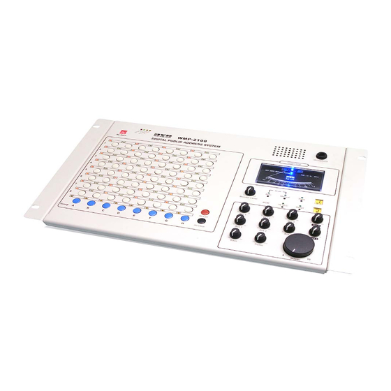
Summary of Contents for BXB Electronics WMP-2100
-
Page 2: Table Of Contents
WMP-60 DIP switch setting: ......................12 b. WMP-60: 200 zones DIP switch chart ..................... 13 III. Linked control for two main console(s) (WMP-2100) ..............14 IV. Connection for extension control device (WMP-2100A) ..............15 V. Connection for Graphical Control Software ..................16 VI. -
Page 3: Safety Instructions
Safety Instructions 1. Please read and observe these instructions before installing and using the apparatus. Use only accessories specified by the manufacturer. The manufacturer is not liable for damage caused by the use of non-specified accessories. 3. Install the apparatus and its accessories carefully. Strike and fierce shaking may damage the apparatus. - Page 4 Warning: Do not disassemble or remodel the product, as these actions may lead to electrical shock or damage. The guarantee on the product will become null if the product is ever disassembled. BXB and the logo are trademark or registered trademarks of BXB Electronics...
-
Page 5: System Installation Instructions
www.BXB.tw System Installation Instructions 1. Rear Panel Function MIC-1~MIC-4: Microphone inputs (MIC1 has priority to broadcast) Functions: AUX1~AUX4: Aux inputs (for CD, tape cassette, radio and timer...) ○ AUX 1 should be reserved for telephone broadcasting ○ AUX OUTPUT:For external amplifiers or recorders Telephone broadcasting interface:... - Page 6 broadcasting, the connector will output DC 5V which can be applied to flash alarm (BXB WS-335T) Remote Control:Dry contacts trigger connector. When broadcasting, the ○ connector becomes a short circuit; it can be used to switch on other equipments as well. ...
-
Page 7: Main Control Cable And Wmp-2100 Configuration
POWER AUTO FUSE AUTO FUSE Fig . 1 Connection structure between WMP-2100 and WMP-7C Wires configuration of WMP-2100 features color management, there are seven different control cables to transmit signals. Every colored cable is designed for a unique function as shown below. - Page 8 Warning: 1. For maintenance and installation, please refer to the chart above. 2. Every wire has its unique function so please make sure the wiring is correct before turning on the unit. Otherwise, incorrect wiring might cause damage to it. (Please refer to Quick Check Installations). 3.
-
Page 9: Connection Between Main Cable And Remote Decoder
II. Connection between Main Cable and Remote Decoder Connection instructions: . Remote Decoder (WMP-60) is built inside BXB speakers (e.g. WS-665AM/60D & WS-817ALM/60D; WS-665T/60D & WS-817TL/60D) . Remote Decoder (WMP-60) is attached to the outside. 1. Remote Decoder (WMP-60) is built in BXB speakers: a. -
Page 10: Remote Decoder (Wmp-60) Is Attached To The Outside
2. Remote Decoder (WMP-60) is attached to the outside. ※ Note The connection applies to any kind of high speakers. (Chart 3) 1. Parallel connection and color management is applied. Simply connect green to green, white to white, blue to blue, red to red…etc. 2. -
Page 11: Remote Decoder (Wmp-60) Is Attached To The Outside Of Bxb Amplifier Teaching Speaker
3. Remote Decoder (WMP-60) is attached to the outside of BXB amplifier teaching speaker. Please refer to Fig. 4 for connection instructions. 7C + 1 white PVC composite backbone OUT B+ G 100V ID S.W MIC Volume control AUX Volume control alarm speaker Fig. -
Page 12: Positions And Setting Of Broadcast Dip Switches
5. Positions and setting of broadcast DIP switches Easily change broadcasting zone from the back of BXB speaker or on remote decoder (WMP-60). Where you can find it: WMP-60 Remote Decoder BXB Speakers with built-in decoder (WMP-60D) Amplifier Teaching Speakers: WS-665Am/60D &... -
Page 13: Wmp-60 Dip Switch Setting
a. WMP-60 DIP switch setting: Each switch on decoder represents one-bit binary value. The values of all switches in the DIP package are interpreted as one number. Definition: GP= Group code(To set Group 1~8, all ON is 7, all OFF is 8) Example 1:Code 305 ... -
Page 14: Wmp-60: 200 Zones Dip Switch Chart
b. WMP-60: 200 zones DIP switch chart... -
Page 15: Linked Control For Two Main Console(S) (Wmp-2100)
Fig. 6 connecting instructions for multiple WMP-2100s ※ Note 1. WMP-2100 is able to connect other WMP-2100(s) (Fig.6 ) and work mutually. 2. A 9-core control cable and a 2-core audio source cable are essential. 3. Distance between two consoles should be less than 1km (0.6 mile). If the... -
Page 16: Connection For Extension Control Device (Wmp-2100A)
IV. Connection for extension control device (WMP-2100A) ※ Instructions: 1. WMP-2100 can connect up to 2 extension control units (64 zones each), in total supports 192 broadcast zones at most. 2. Every console has 8 memorable control group buttons, which means included 2 extension control devices;... -
Page 17: Connection For Graphical Control Software
COM 1 Fig. 8 Connection between Graphical Control Software and WMP-2100 ※ Note 1. WMP-2100 is compliant to PA control software, refer to Fig. 8 for connection (Fig. 8). 2. Parallel RS-232 cable (without jump wire) is required. 3. Simply complete setup by connecting RS-232 on PC Server. -
Page 18: Connection For Telephone Broadcasting System
VI. Connection for Telephone broadcasting system Fig 9. PBX (private branch exchange) and WMP-2100 Simply connect a 2-core cable to PBX external ports to activate telephone broadcasting, refer to Fig.9 for connection. ※ Note 1. You can activate telephone broadcasting on the phone without operating the main unit. -
Page 19: External Activated Port And Installation
VII. External activated port and installation 1. There are 2 external trigger connectors on main controller, which apply to a timer clock and other flip-flops. 2. Two external control wipers function: ◎ ALL CALL+COM Broadcast to all zones ◎ 8 GROUP+COM Broadcast to Group 8 3. -
Page 20: Aux Input Description & Application
VIII. AUX Input Description & Application 1. MIC Input: a. MIC-1 has priority to broadcast, which can be used for emergency broadcasting. When broadcasting, other audio source will be mute. Sounds will resume once finish. b. MIC-4 on the real panel and MICRO PHONE input on the front panel work in parallel. -
Page 21: Inspection For Wire Configuration
After the whole system is completely installed, connection and impedance value should be inspected carefully. If one of the cables is short-circuited, ★ WMP-2100 will be seriously damaged and malfunction. Please refer to the following instructions: Required tools: ◎ VOM (Volt-Ohm-Milliammeter): Measuring if the cables and high-pressure signal wires are short-circuited. - Page 22 If that happens, use 1/2 troubleshooting method to examine. Connect the cables to WMP-2100 after examining. ☆ After examining, turn on WMP-2100 and it will start auto-scanning. Make sure all the decoders work properly then connect high-pressure signal lines to a power amplifier.
-
Page 23: System Structure
X. System Structure...
Need help?
Do you have a question about the WMP-2100 and is the answer not in the manual?
Questions and answers