Table of Contents
Advertisement
Quick Links
Advertisement
Table of Contents
Troubleshooting

Subscribe to Our Youtube Channel
Related Manuals for Allen-Bradley 825-P

Summary of Contents for Allen-Bradley 825-P
- Page 1 User Manual Modular Protection System for Motors Catalog Number 825-P...
-
Page 2: Important User Information
Rockwell Automation publication SGI-1.1, Safety Guidelines for the Application, Installation and Maintenance of Solid- State Control (available from your local Allen-Bradley distributor), describes some important differences between solid- state equipment and electromechanical devices that should be taken into consideration when applying products such as those described in this publication. -
Page 3: European Communities (Ec) Directive Compliance
European Communities (EC) Directive Compliance If this product has the CE mark it is approved for installation within the European Union and European Economic Area (EEA). It has been designed and tested to meet the following directives. EMC Directives This product is tested to meet the Council Directive 89/336/EEC Electromagnetic Compatibility (EMC) by applying the following standards, in whole: •... - Page 4 Rockwell Automation Publication 825-UM004D-EN-P - November...
-
Page 5: Table Of Contents
Table of Contents Important User Information ........2 European Communities (EC) Directive Compliance . - Page 6 Table of Contents Chapter 4 Hardware Commissioning Connecting a Converter Module (MCM) ......45 Adding an Optional I/O Card ........47 Adding the Optional Voltage Card.
- Page 7 Table of Contents Current Imbalance/ Phase Loss ............78 Protection Disable .
- Page 8 Table of Contents SER Triggering ..........110 Example Reports .
- Page 9 Table of Contents Selected Functional Tests ........151 Periodic Tests (Routine Maintenance) .
- Page 10 Table of Contents Main Circuits ..........187 Control Circuits .
-
Page 11: Preface
• Chapter 1: Introduction Describes the basic features and functions of the 825-P. • Chapter 2: Installation Describes how to mount and wire the 825-P; illustrates wiring connections for various applications. • Chapter 3: Front Panel Operation Explains features and use of the front panel, including front-panel command menu, default displays, and automatic messages. -
Page 12: Conventions
Examples This instruction manual uses several example illustrations and instructions to explain how to effectively operate the 825-P. These examples are for demonstration purposes only. The firmware identification information or settings values included in these examples may not necessarily match those in the current version of your 825-P. -
Page 13: Introduction
This manual contains the information for installing, setting, testing, operating, and maintaining an 825-P. It is not necessary to review the entire manual to perform specific tasks. A Quick Start Guide, Publication 825-QS001, is also available. It will help to step the first-time user through the device commissioning process. -
Page 14: Options And Accessories
Up to 12 RTDs can be monitored when an external 825-PR12D RTD Scanner is used. There are separate trip and warn settings for each RTD. Monitoring Features The monitoring features of the 825-P are as follows: • Event summaries contain relay ID, date and time, trip cause, and current/ voltage magnitudes. -
Page 15: Applications
RTD scanner to the 825-P (e.g., part# 1570FCBL- MM-SX-62-STST-2M from Ultra Spec Cable - http://store.ultraspec.us). Applications The 825-P can be used with the following across the line starter applications: • Low and medium voltage with 2 or 3 potential transformers • With or without phase current transformers •... - Page 16 Chapter 1 Introduction Figure 1 - AC Connections Without CTs Converter Module Cat. No. 825-MCM2 Cat. No. 825-MCM5 Cat. No. 825-MCM20 Cat. No. 825-MCM180 Cat. No. 825-MCM420 Cat. No. 825-MCM630N 825-MCM 825-P Rockwell Automation Publication 825-UM004D-EN-P - November 2012...
-
Page 17: Installation
Refer to Appendix:A Specifications for environmental ratings. Relay Mounting To flush mount the 825-P in a panel, cut a rectangular hole with the dimensions shown in Figure 2. Figure 2 - Relay Mounted In a Panel Legend (in) Mounting Panel–maximum thickness 6.5 mm... -
Page 18: Rear-Panel Connections
Chapter 2 Installation Rear-Panel Connections Rear-Panel Diagram The physical layout of the connectors on the rear-panel of a fully configured 825-P is shown in Figure 3. Figure 3 - Rear-Panel Layout Factory Ground Factory Configured Screw Configured Converter Module Input 0.31 in... -
Page 19: Top-Panel Diagram
Top-Panel Diagram The input and output designations for the rear-panel connectors of a fully configured 825-P are shown in Figure 4. This diagram is located on the top panel of the relay. Figure 4 - Top-Panel Input and Output Designations ‡... -
Page 20: I/O Diagram
110…250 V DC 24 or 120V AC/+V DC 24V AC/+V DC F/O Cable to RTD Scanner Analog Out + / H Y14 Y12 Y26 Y24 Y22 I – 825-P Relay Aux2 Aux3 Aux4 Aux5 Aux6 Aux1 Trip Alarm Y2–... -
Page 21: Ac/Control Connection Diagrams
• The Trip relay coil is energized continuously. • When the 825-P generates a trip signal, the Trip relay coil is de-energized. • The Trip relay coil is also de-energized if the 825-P input power is removed or if the 825-P fails (self-test status is FAIL). - Page 22 Chapter 2 Installation Figure 6 - TRIP Relay Output Contact Configurations Fail-Safe Tripping ( ) Non-Fail-Safe Tripping NOTE: Contact numbering changes are based on the TRIP Fail-Safe Setting. Figure 7 shows fail-safe and non-fail-safe wiring methods to control breakers and contactors.
-
Page 23: Converter Module Connection
Figure 8 - Converter Module Connection 4 M Connection Cable (supplied with MCM) NOTE: The 825-P relay is not EMC-tested for converter module connecting cable lengths greater than the 4-meter cable that is supplied. Figure 9 - Converter Module Dimensions ø e ø... -
Page 24: Core Balance Current Transformer Connections
Chapter 2 Installation Core Balance Current Transformer Connections Figure 10 - Core Balance Current Transformer Connections 0.31 in DEVICENET MCM/CWE 8.0 mm ! ! ! MODULE 825-CBCT Ground Fault Sensor (or customer-supplied STATUS NETWORK equivalent) STATUS CBCT DATA RATE 0 = 125K 1 = 250K 2= 500K 157-0138... -
Page 25: Voltage Connections
VT connected. Figure 12 shows the three methods of connecting three-phase voltages. Figure 12 - Voltage Connections Direct Connection (Xfmr Connection = Wye) F1, F2, and F3 are fuses. 825-P Wye-Wye VT Connection (Xfmr Connection = Wye) 825-P Open-Delta VT Connection (Xfmr Connection = Delta) 825-P The recommended fuse is the Bussman KTK - 1/10, 1/10 ampere Limitron®... -
Page 26: Full-Voltage Non-Reversing Starter
Cat. No. 825-MCM5 Cat. No. 825-MCM20 Cat. No. 825-MCM180 Cat. No. 825-MCM420 Cat. No. 825-MCM630N 825-MCM 825-P Figure 14 - AC Connections with CBCT 825-MCM 825-P T2 Core Balance Transformer Current ratio of core balance current transformer: 1...2000:1 Output from core balance current transformer: 0...500mA... - Page 27 NOTE: For AUX1 to work as an alarm/warning indicator, it must be mapped to the "Warning" function bit. AUX1 825-P NOTE: For AUX1 to work as an alarm/warning indicator, it must be mapped to the “Warning” function bit. Rockwell Automation Publication 825-UM004D-EN-P - November 2012...
-
Page 28: Full-Voltage Reversing Starter
• MOTOR LRT-2nd = LOCKED ROTOR TIME • ACCEL FACT-2nd = ACCEL FACTOR • RUN ST TC-2nd = RUN STATE TIME K Figure 17 - AC Connections for Full-voltage Reversing Starter 825-MCM 825-P 24V AC/V DC (II) Y12 Y1- 825-P... - Page 29 Installation Chapter 2 Figure 18 - AC Connections for Star-Delta Starting 825-MCM 825-P U1 Converter Module Cat. No. 825-MCM2 Cat. No. 825-MCM5 Cat. No. 825-MCM20 Cat. No. 825-MCM180 Cat. No. 825-MCM420 Cat. No. 825-MCM630N Rockwell Automation Publication 825-UM004D-EN-P - November 2012...
-
Page 30: Two-Speed Motor
NOTE: For AUX1 to work as an alarm/warning A1 13 indicator, it must be mapped to the "Warning" function bit. AUX1 825-P A2 14 AUX6 AUX5 825-P NOTE: For AUX1 to work as an alarm/warning indicator, it must be mapped to the “Warning”... -
Page 31: Field Serviceability
If your facility is not equipped to work with these components, contact Rockwell Automation about returning this device and related Rockwell Automation equipment for service. The 825-P firmware can be upgraded in the field; refer to Chapter Field Serviceability Firmware Upgrade Instructions. -
Page 32: Fuse Replacement
Chapter 2 Installation Fuse Replacement To replace the Power Supply fuse, do the following: 1. De-energize the relay. 2. Remove the eight rear-panel screws, the ground screw, and the relay rear- panel. 3. Remove the Slot A printed circuit board. 4. -
Page 33: Front Panel Operation
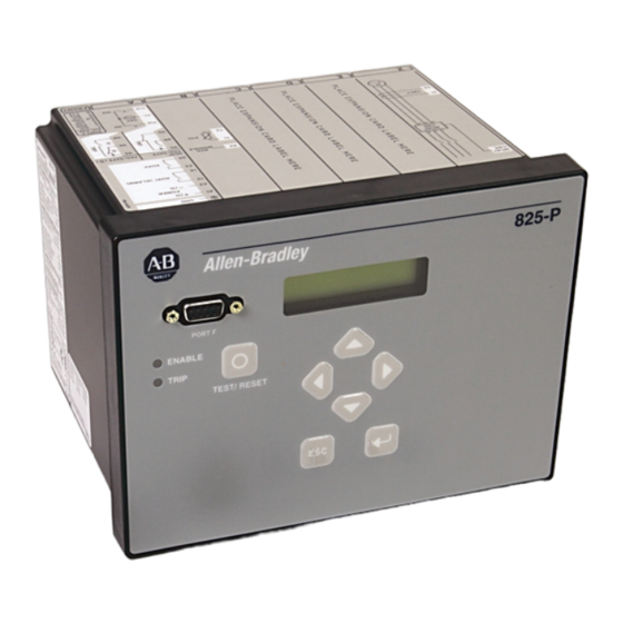
Chapter Front Panel Operation Front Panel Layout The 825-P Relay front-panel interface consists of two LEDs, an LCD display, a seven-button keypad, and an EIA-232 serial port connector. The front-panel layout is shown in Figure 22. Figure 22 - Relay Front Panel... -
Page 34: Front Panel Automatic Messages
Chapter 3 Front Panel Operation The display changes for the following relay conditions in the order of precedence (see Table 3): • Status failure • Trip condition time to trip (if under 10000 seconds) • Warning • Lockout start request •... -
Page 35: Front Panel Menus And Operations
• Min Off Lockout • Restart Lockout Front Panel Menus The 825-P front panel gives you access to most of the information that the relay measures and stores. You can also use the front panel controls to view or modify and Operations relay settings. - Page 36 Chapter 3 Front Panel Operation Table 4 - Front Panel Push Button Functions Push Button Function UpArrow Move up within a menu or data list. While editing a setting value, increase the value of the underlined digit. DownArrow Move down within a menu or data list. While editing a setting value, decrease the value of the underlined digit.
-
Page 37: Front Panel Security
Front Panel Operation Chapter 3 Front Panel Security Front Panel Access Levels The relay front panel typically operates at Access Level 1 and allows any user to view relay measurements and settings. Some activities, such as editing settings and controlling output contacts, are restricted to those operators who know the relay Access Level 2 password when enabled. - Page 38 Chapter 3 Front Panel Operation Figure 26 - Password Entry Screen Password= Del Clr Accept A B C D E F G H I J K L M N O P Q R S T U V W X Y Z ..a b c d e f g h i j k l m n o p q r s t u v w x...
- Page 39 Front Panel Operation Chapter 3 9. If the password is incorrect, the relay displays the message Invalid Password. 10. Press the Enter push button to return to your previous task. To Correct Entry Errors To correct password entries, do the following: 1.
-
Page 40: Front Panel Main Menu
Chapter 3 Front Panel Operation Front Panel Main Menu All access to information and relay settings through the front panel starts at the relay main menu. The remainder of this section describes the use of the main and lower level menus. Main Meter Events... -
Page 41: View Or Change Settings Using The Front Panel
Select Yes to save the settings changes and No to discard the changes. NOTE: Each 825-P is shipped with default factory settings. Calculate the settings for your motor to ensure secure and dependable protection. Figure 27 shows a front-panel menu navigation example to enter the Phase Rotation (ABC, ACB) setting. - Page 42 Chapter 3 Front Panel Operation Figure 27 - Front Panel Setting Entry Example Main Menu Meter Events Press to move within the list. Motor Monitor Targets Set/Show Status Press to select an underlined menu item. Reset TCU Set/Show Menu RELAY PORT IO ASSIGN Press to return...
-
Page 43: Setting Entry Error Messages
Front Panel Operation Chapter 3 Setting Entry Error Messages As you enter relay settings, the relay checks the setting entered against the setting’s own range as published on the relay setting sheet. If an entered setting falls outside its range, the relay immediately responds with the message “Out of Range”... - Page 44 Chapter 3 Front Panel Operation Rockwell Automation Publication 825-UM004D-EN-P - November 2012...
-
Page 45: Connecting A Converter Module (Mcm)
Chapter Hardware Commissioning All hardware that is added to the 825-P must be installed and commissioned individually. Listed below are the processes required to commission an 825-P for a specific Converter Module, Optional I/O Module, Optional Voltage Module, and Optional Communication Module. - Page 46 Chapter 4 Hardware Commissioning • Select Yes to confirm the new hardware configuration, and the display will show: Config Accepted Enter to Reboot • Press Enter to reboot the relay. • If existing configuration parameters are not proper for the specific hardware configuration, then the following message will be displayed Setting Mismatch Adjust Settings...
-
Page 47: Adding An Optional I/O Card
Adding an Optional I/O Card • Remove control power from the relay, and remove the back cover • Add the optional I/O card into Slot D in the 825-P • Replace the cover and reapply control power to the relay •... -
Page 48: Adding The Optional
Adding the Optional • Remove control power from the relay, and remove the back cover • Add the optional Voltage Card into Slot E in the 825-P Voltage Card • Replace the cover and reapply control power to the relay •... -
Page 49: Adding The Optional Communication Card
Adding the Optional • Remove control power from the relay, and remove the back cover • Add the optional communication card into Slot C in the 825-P Communication Card • Replace the cover and reapply control power to the relay •... -
Page 50: Removing An Option Card
Removing an Option Card • Remove control power from the relay, and remove the back cover • Remove the option card from the 825-P • Replace the cover and reapply control power to the relay • The display will show the following message to indicate that something is... -
Page 51: Software Overview
The MPS Explorer software allows users to access settings and data on Modular Protection Systems (MPS) for motors. The 825-P connects to a PC via the serial communications port (Port F) on the front face where settings can be configured. -
Page 52: Connection/Access Level
Access Level 1: This level allows only monitoring of parameter and metering values. Access Level 2: Full access to the 825-P, including the configuration of parameter values. To change access levels, select the appropriate button. The access levels must be changed in ascending order. -
Page 53: Save/Open
Configurable output with a specified percentage of the full analog output current for a defined period of time View motor operation statistics Displays the operating statistics of the motor connected to the 825-P View serialized events Display, sort, and export the serialized event data... -
Page 54: Ana (Test Analog Output)
MOT (Motor Operating Statistics) The Motor Operating Statistics function displays the operating statistics of the motor that is connected to the 825-P relay. Newer firmware versions (R107+) display the trip and alarm accumulators. Rockwell Automation Publication 825-UM004D-EN-P - November 2012... -
Page 55: Ser (Serialized Events Recording)
Events starting with the date entered up to the most recent event Clear Device: Physically clear the serialized events from the 825-P. This cannot be recovered. Export: CSV: Export the data in the list to a Comma Separated Value file. -
Page 56: Sum (Events Summary Report)
Chapter 5 Using MPS Explorer is able to confirm or ignore the changes from this screen. The relay will reboot when the hardware changes are confirmed. SUM (Events Summary Report) The Event Summary Report function displays the five most recent events Rockwell Automation Publication 825-UM004D-EN-P - November 2012... -
Page 57: Met (Instantaneous Metering)
Using MPS Explorer Chapter 5 MET (Instantaneous Metering) RTD (RTD/Thermal Metering) The Instantaneous and Thermal Metering functions display the collection and export data in real time. The user is able to configure the parameters that are displayed for both instantaneous and thermal metering. Rockwell Automation Publication 825-UM004D-EN-P - November 2012... -
Page 58: Tar (Display Target Words)
Chapter 5 Using MPS Explorer TAR (Display Target Words) The Display Target Words function shows the status of relay elements and is independent from the main window. To view the full bit description, place the cursor over any masked heading. Dialog buttons function as follows: Start: Begin data collection based on the contents of the Times and Interval boxes... -
Page 59: Data Visualization/Trending
Using MPS Explorer Chapter 5 Data Visualization/Trending MPS Data Visualization and Trending allow the user to configure the display with specific metering data as well as Relay Word Bits that are then mapped to graphs, gauges and bit indicators so that parameters can be monitored visually. Each indicator auto scales to provide the best fit for the data for easy viewing. - Page 60 Chapter 5 Using MPS Explorer both are highlighted, use the arrow located in the middle to move the parameter to its assignment. Rockwell Automation Publication 825-UM004D-EN-P - November 2012...
-
Page 61: Validate Settings
Using MPS Explorer Chapter 5 The Data Acquisition Settings also allows the user to map specific hardware data to indicators that are displayed on the screen. The control type can be changed via the Bits, Gauges and Graphs tab along the top of the window. The Layout tab, shown below, can be used to view the correlation between control numbers and their position on the main trending window. -
Page 62: I/O Mapping
Chapter 5 Using MPS Explorer A list of possible errors will appear showing the name and problem that may contribute to an error. I/O Mapping MPS Explorer allows the user to easily configure the I/O Map to assign protection trip functions to the Trip relay, assign functions to the auxiliary relay and assign functions to the selected input. -
Page 63: Resetting/Restoring
Using MPS Explorer Chapter 5 Resetting/Restoring Restoring Parameter Values Software: Navigate to MPS > Parameters > Open Default Settings to restore the default program settings or the settings in the specified file. The hardware settings will not be restored until the settings are downloaded to the device. Hardware: Navigate to MPS >... - Page 64 Chapter 5 Using MPS Explorer Rockwell Automation Publication 825-UM004D-EN-P - November 2012...
-
Page 65: Overview
This chapter describes configuring the 825-P relay settings for motor protection, basic functions, I/O mapping, and communications. NOTE: Each 825-P is shipped with default factory settings. Calculate the settings for your motor to ensure secure, dependable protection. This chapter includes the following subsections: •... -
Page 66: Application Data
16 Characters Prot. System The 825-P prints the Relay and Terminal Identifier strings at the top of responses to serial port commands to identify messages from individual relays. Enter up to 16 characters, including capital letters A…Z, numbers 0…9, periods (.), dashes (-), and spaces. -
Page 67: Phase Rotation, Nominal Frequency Settings
Configuring Protection & Logic Functions Chapter 6 Phase Rotation, Nominal Frequency Settings Table 8 - Phase Rotation, Nominal Frequency Settings Setting Prompt Setting Range Factory Default PHASE ROTATION ABC, ACB RATED FREQUENCY 50, 60 Hz DATE FORMAT MDY, YMD, DMY The phase rotation setting tells the relay your phase labeling standard. -
Page 68: Settings
Chapter 6 Configuring Protection & Logic Functions Current Transformer (CT) Configuration, Full Load Current Settings Table 9 - CT Configuration and Full Load Current Settings Setting Prompt Setting Range Factory Default PHASE CT RATIO 1…5000 MOTOR FLA (I 0.5…5000 A TWO SPEED ENABLE Y, N CT RATIO–2nd... -
Page 69: Voltage Transformer (Vt) Configuration Settings
Configuring Protection & Logic Functions Chapter 6 Voltage Transformer (VT) Configuration Settings Relays that are not equipped with phase voltage inputs will hide these settings and disable voltage-based protection and metering functions. Table 10 shows voltage settings for relay models with optional voltage inputs. Table 10 - CT Configuration and Full Load Current Settings Setting Prompt Setting Range... -
Page 70: Overload (Thermal Model)
Chapter 6 Configuring Protection & Logic Functions Overload (Thermal Model) The 825-P motor thermal element provides integrated protection for all of the following motor operating conditions: • Locked rotor starts • Running overload • Imbalance current/negative-sequence current heating • Repeated or frequent starting NOTE: You can set the Run State Time Constant of the thermal overload curve. - Page 71 Obtain the requested information (except the acceleration factor) from the motor specifications. The 825-P thermal element always operates in one of two modes: starting or running. In starting mode, the thermal element trips in Locked Rotor Time at Locked Rotor Current whether the motor is at ambient or at normal operating temperature.
- Page 72 Chapter 6 Configuring Protection & Logic Functions Thermal Element Setting EXAMPLE A 4000V 600 Hp motor is protected using the 825-P Thermal Overload Element. Motor data sheet includes the following: • Rated Horsepower = 600 Hp • Rated Voltage = 4000V •...
- Page 73 Set START INH. LEVEL to a value equal to the incremental increase in percent thermal capacity utilized for one start plus additional margin. The 825-P allows a new start when the percent thermal capacity utilized value is below 100 - START INH.
-
Page 74: Short Circuit
0.00…5.00 s 0.50 If the 825-P is connected to a motor protected by a fused contactor, disable the short circuit element by setting its Trip level to Off. If the relay is connected to a device capable of interrupting fault current, use the element to detect and trip for short circuit faults. -
Page 75: Ground Fault
Configuring Protection & Logic Functions Chapter 6 When the harmonic distortion index is below the fixed threshold, the short circuit overcurrent elements operate on the output of the cosine filter. The cosine filter provides excellent performance in removing DC offset and harmonics. - Page 76 Chapter 6 Configuring Protection & Logic Functions When a ground-fault CT is connected to the 825-P, as in Figure 14, use the CB ground-fault element to detect motor ground faults. Calculate the Trip and Warn level settings based on the available ground fault current and the CB CT ratio.
-
Page 77: Jam
Configuring Protection & Logic Functions Chapter 6 Table 17 - Jam Settings Setting Prompt Setting Range Factory Default Off, 1.00…6.00 x I JAM TRIP LEVEL JAM TRIP DELAY 0.0…120.0 s Off, 1.00…6.00 x I JAM WARN LEVEL JAM WARN DELAY 0.0…120.0 s 10.0 When the motor is running, the relay offers jam detection. -
Page 78: Current Imbalance
The 825-P calculates percent imbalance current in one of two ways, depending on the magnitude of the average current. -
Page 79: Protection Disable
Overload (Thermal Model) element. If you are using the time delay settings, keep them as short as possible. NOTE: The 825-P determines the motor state (Starting, Running, or Stopped) primarily based on the motor current. Start Monitoring Table 21 - Start Monitor Settings... -
Page 80: Star-Delta (Wye-Delta) Starting
In addition to enabling the Star-Delta, you must assign Star and Delta to Auxiliary output relays (one each). The 825-P issues the command to switch from Star to Delta (Wye to Delta) as soon as the starting current has dropped to the rated value and the motor has reached its normal speed in Star (Wye). -
Page 81: Start Inhibit
PH REV. ENABLE Y, N The 825-P uses phase currents or phase voltages (if available) to determine that the phase rotation of signals applied to the relay matches the phase rotation setting. When you set Ph. Rev. Enable equal to Y, the relay trips 0.5 seconds after incorrect phase rotation signals are applied to the relay. -
Page 82: Speed Switch
Chapter 6 Configuring Protection & Logic Functions Speed Switch (Stalling During Start) Table 25 - Speed Switch Settings Setting Prompt Setting Range Factory Default SS TRIP DELAY Off, 1…240 s SS WARN DELAY Off, 1…240 s NOTE: In addition to setting the SS DELAY, you must connect the speed switch contact to an input assigned to Speed Switch (see Table 44 and Figure 5, Figure 20, and Figure 21 for connection diagrams). -
Page 83: Rtd-Based Protection
See Figure 4 for the location of the RTD module fiber-optic cable connector. NOTE: The 825-P can monitor up to 12 RTDs connected to the 825-PR12D Module. Table 27 shows Location, Type, and Trip/Warn Level settings only for RTD1; settings for RTD2 through RTD12 are similar. - Page 84 NOTE: A fiber optic cable is not included with the 825-PR12D. A simplex 62.5/125 μm fiber-optic cable with ST connector is needed for connecting the 825-PR12D to the 825-P (eg., part# 1570FCBL-MM-SX-62-STST-2M from Ultra Spec Cable - http://store.ultraspec.us). Table 27 - RTD Settings...
- Page 85 • 120-ohm nickel (NI120) • 10-ohm copper (CU10) The 825-P provides temperature warnings and trips using the RTD temperature measurements and the warning and trip temperature settings in Table 27. The relay issues a winding temperature warning if any of the healthy winding RTDs (RTD Location setting equals WDG) indicate a temperature greater than the corresponding RTD Warning Temperature setting.
-
Page 86: Voltage-Based Protection
1°C reduction in RTD Trip Temperature for each 1°C rise in ambient temperature over 40°C. When you enable RTD biasing, the 825-P automatically reduces the RTD Trip Temperatures for all winding RTDs when ambient temperature is above 40°C. -
Page 87: Overvoltage
Off, 1.00…1.20 xVnm OV WARN DELAY 0.0…120.0 s When you connect the 825-P voltage inputs to phase-to-phase connected PTs, as in Figure 12, the relay provides two levels of phase-to-phase overvoltage and undervoltage elements. When you connect the 825-P voltage inputs to phase-to-neutral connected PTs, as in Figure 12, the relay provides two levels of phase-to-neutral overvoltage and undervoltage elements. -
Page 88: Underpower
Chapter 6 Configuring Protection & Logic Functions For relay application on an induction motor, it is recommended that the installer disable the elements by setting both the Negative VAR Warn Level and Negative VAR Trip Level settings to Off. Underpower Table 31 - Underpower Settings Setting Prompt Setting Range... -
Page 89: Frequency
The setting range for Trip and Warn Levels shown in Table 33 are for Rated Freq. := 60 Hz. The setting ranges are “Off, 45.0–55.0 Hz” when Rated Freq. := 50 Hz. The 825-P provides two warning and two trip overfrequency or underfrequency elements with independent level and time-delay settings. When an element level setting is less than the Nominal Frequency setting, the element operates as an underfrequency element. -
Page 90: I/O Configuration
LOWER to auxiliary output relays (one each); see Table 43, and Figure 16 for connection diagrams. The 825-P provides an ability to control external devices based on parameter Load Control Selection. You can select Current, Power, or Thermal Capacity Utilized to operate auxiliary outputs. -
Page 91: Trip Inhibit (Block)
Configuring Protection & Logic Functions Chapter 6 Select LOAD_I to scale the analog output based on motor current if the output is not of interest during overload conditions. Select either AVG_I or MAX_I to scale the analog output based on motor current and if the output is required during overload conditions. -
Page 92: Output Relay Behavior
AUX6 FAIL-SAFE Y, N The 825-P allows you to enable fail-safe output contact operation for relay contacts on an individual basis. When contact fail-safe is enabled, the relay output is held in its energized position when relay control power is applied and falls to its de-energized position when control power is removed. -
Page 93: Timer Function
Configuring Protection & Logic Functions Chapter 6 Timer Function Table 39 - Timer Settings Setting Prompt Setting Range Factory Default ON DELAY T1 0…240 s OFF DELAY T1 0…240 s ON DELAY T2 0…240 s OFF DELAY T2 0…240 s NOTE: In addition to setting the On and Off Delays, you must assign TIMER1 and/or TIMER2 to a control input (see Table 44). -
Page 94: Display Enable
Chapter 6 Configuring Protection & Logic Functions The LCD TIMEOUT indicates the duration of inactivity before the LCD backlight will extinguish, the Access Level will be automatically reset and the present function will be automatically terminated. Use the front panel LCD Timeout setting as a security measure. -
Page 95: I/O Assignments
Comm Loss Remote Trip Comm Fault Reserved Reserved Reserved Reserved NOTE: The 825-P uses settings TRIPA through TRIPD and setting TRIP FAIL-SAFE (see Table 38) to determine the operation of the Trip Output. Rockwell Automation Publication 825-UM004D-EN-P - November 2012... - Page 96 Chapter 6 Configuring Protection & Logic Functions The 825-P allows mapping of protection trip elements to the trip output. Table 42 shows the method of mapping elements using Relay Word bits associated with elements. Select 1 for each element you want to map using the TRIPA through TRIPD settings.
- Page 97 Configuring Protection & Logic Functions Chapter 6 Table 43 - Aux Assignments Setting Prompt Description Aux# D Comm Idle Comm Loss Remote Trip Comm Fault Latch Trip Reserved Reserved Reserved Aux# E Overload Warning Undercurrent Warning Jam Warning Current Imbalance Warning RTD (Winding/Bearing) Warning Power Factor Warning Ground Fault (Core Balance) Warning...
- Page 98 Start Command Network Control Reserved NOTE: The 825-P uses settings AUX# A through AUX# H and setting AUX# FAIL-SAFE in the output logic (see Table 38 for more details) to determine the operation of the corresponding auxiliary. NOTE: The AUX# A through AUX# D bytes are used to map trip functions to the output. The AUX# E through AUX# H bytes are used to map warning and status functions to the output.
- Page 99 Breaker/Contactor Auxiliary Remote Trip NOTE: The 825-P allows one control function to an input and one input to a control function (see Table 5). NOTE: In addition to setting an Input Assignment, you must connect a control contact to the input (see Figure 16 for a typical connection diagram).
-
Page 100: Logic Explanation
Speed 2 When the SPEED2 control input is asserted and Two Speed Enable setting is Y the 825-P selects second values for the settings. See Table 11 for a full description of various settings. Use the SPEED2 input for two-speed motor applications. You can also use this input to change the settings in applications where ambient temperature varies appreciably (e.g., exposed water pumps with different capacities during daytime... -
Page 101: Start & Emergency Restart Logic
Configuring Protection & Logic Functions Chapter 6 The relay automatically locks out the trip relay by asserting the trip signal under any of the following start-inhibiting conditions: • Restart (Anti-backspin) Block The restart block timer has not expired since the motor trip occurred. The trip condition is maintained until the timer expires. - Page 102 Chapter 6 Configuring Protection & Logic Functions The relay asserts the Emergency Restart bit in response to any of the following conditions: • the control input assigned to Emergency Restart asserts. • the relay receives a network Emergency Restart control command. When the Emergency Restart bit asserts, the relay does the following: •...
-
Page 103: Overload Curves
Configuring Protection & Logic Functions Chapter 6 Overload Curves Figure 34 - Thermal Overload Curves 100000 Trip times are for cold (ambient) motor, without preload. Relay Settings Service Factor, SF = 1.01 Acceleration Factor, TD = 1.00 Run State Time Constant, RTC = Auto Motor LRC = 6.0 •... - Page 104 Chapter 6 Configuring Protection & Logic Functions Rockwell Automation Publication 825-UM004D-EN-P - November 2012...
-
Page 105: Metering & Monitoring
Note that the phases and neutral are identified by 1, 2, 3, N for currents and A, B, C, N for voltages. Table 46 details each of the meter data types in the 825-P. Chapter 3: Front Panel Operation and Chapter 5: Using MPS Explorer describe how to access the various types of meter data using the relay front-panel and communications ports. -
Page 106: Instantaneous Metering
Chapter 7 Metering & Monitoring Instantaneous Metering Table 46 - Measured Values Relay Option Meter Values All Models Line Currents L1, L2, and L3 IN (Core-Balance Ground Fault Current) magnitudes (A) and phase angles (°) IG (Residual Ground Fault Current) magnitude (A) and phase angle (°) IM (Average Current Magnitude) Average Motor Load (x I Current Imbalance %... -
Page 107: Power Measurement Conventions
I leads V W = + W = – VAR = – VAR = – PF = LEAD PF = LAG In the 825-P, reported positive real power is always into the motor. Rockwell Automation Publication 825-UM004D-EN-P - November 2012... -
Page 108: Motor Operating Statistics
Chapter 7 Metering & Monitoring Motor Operating Statistics The 825-P retains useful machine operating statistics information regarding the protected motor. NOTE: While the relay power is off, the elapsed timers do not advance. If relay power is off for a significant amount of time, the elapsed calendar time does not match the elapsed time recorded by the relay. -
Page 109: Analyzing Events
• Serialized Events Recording Event Summary Reports Each time the 825-P trips and in response to other selected conditions, it captures motor current and voltage (if included). This collection of data is called an event summary report. This section explains what causes the relay to save an event summary report, and what the event summary data means. -
Page 110: Serialized Events Recording (Ser) Report
SER Triggering Recording (SER) Report The 825-P relay stores an entry in the SER report for a change of state of any one of the elements listed in Table 112 on page 235 and Table 113 on page 238. The relay saves up to 512 records in nonvolatile memory. -
Page 111: Example Reports
Event Summary Report The example event summary report in Figure 36 corresponds to the example Serialized Events Recording (SER) report in Figure 37. Figure 36 - Example Event Summary Report =>SUM <Enter> 825-P Modular Date: 06/07/2003 Time: 14:50:06:032 Prot. System... - Page 112 Chapter 8 Analyzing Events Table 50 - Example SER Report Explanations Item # Explanation 11, 10, 9, 8, 7 After a 10-second accelerating time, the motor relay indicates the motor is running (9). Later, the ambient temperature alarm element asserts. 6, 5 The ambient temperature trip element times out, causing the relay to trip.
-
Page 113: Introduction
825-PDN DeviceNet Communication Card Introduction The 825-PDN DeviceNet Communication Card is an optional accessory that enables connection of the 825-P Modular Protection System to the DeviceNet automation network. The card occupies the communication expansion slot (Slot C) in the 825-P Modular Protection System. - Page 114 Chapter 9 825-PDN DeviceNet Communication Card Figure 39 - 825-PDN Component Overview Table 51 - Part Descriptions Part Description DeviceNet Connector Accepts a 5-pin linear DeviceNet plug. Bus Status LED Status indicator for backplane communications. Network Status LED Status indicator for DeviceNet communications. Node Address Switch Rotary switch for setting the most significant digit (MSD) of node address.
-
Page 115: Features
RSNetWorx for DeviceNet. • Status indicators report the status of the device bus and network communications. They are visible from the back panel of the 825-P Modular Protection System as installed. • UCMM (Unconnected Message Manager) messages are supported with the ability to allocate up to 3 explicit message connections concurrently. -
Page 116: Required Equipment
• One DeviceNet communication card • One five-pin linear DeviceNet plug • Two labels that the installer affixes to the 825-P Modular Protection System, one to the top and one to the back panel • 825-P Option Card installation instructions User-Supplied Equipment •... -
Page 117: Node Commissioning
825-PDN DeviceNet Communication Card Chapter 9 Figure 40 - Connecting 5-Pin Linear Plug to DeviceNet Cable Table 52 - Linear Plug Function Descriptions Terminal Color Signal Function Power Supply White Can_H Signal High Bare SHIELD Shield Blue CAN_L Signal Low Black Common 5. -
Page 118: Setting The Hardware Switches
Chapter 9 825-PDN DeviceNet Communication Card Setting the Hardware Switches Use the following steps to commission the card: 1. Set the node address switches. Figure 41 - Node Address and Data Rate Setting Switches Table 53 - Node Address MAC ID Setting Switch Setting Description 0…63... -
Page 119: Using Rsnetworx For Devicenet
5. RSNetWorx now browses the network and displays all of the nodes it has detected on the network. For some versions of RSNetWorx software, the 825-P Modular Protection System EDS files and icon might not be included, and the device could be identified as an unregistered device. - Page 120 Chapter 9 825-PDN DeviceNet Communication Card Figure 42 - Network Online Screen 6. If RSNetWorx recognizes the device as an 825-P Modular Protection System, skip ahead to the section Using the Node Commissioning Tool of RSNetWorx for DeviceNet. Registering an EDS File...
-
Page 121: Explicit Messaging
To assist in the development of the example, the network consists only of the 825-P Modular Protection System and scanner. Therefore, the only mapped information in the scanner is the 825-P Modular Protection System. Rockwell Automation Publication 825-UM004D-EN-P - November 2012... -
Page 122: Setting Up The Msg Instruction
Chapter 9 825-PDN DeviceNet Communication Card The following example utilizes the input and output assemblies of 50 and 2. The tables below list the data configuration for the ControlLogix platform and include the Tag Name as used in the example program. Table 55 - Example ControlLogix Input Addressing (produced assembly) Instance 50 ODVA Overload Byte... - Page 123 Path defines the route the message takes to get to the device it is intended for. In this example the path is Scanner,2,4; where scanner is the name of the 1756-DNB in the rack, 2 represents the DeviceNet port, and 4 represents the physical node address of the 825-P Modular Protection System.
-
Page 124: Devicelogix
Chapter 9 825-PDN DeviceNet Communication Card Figure 44 - Scanner Path DeviceLogix DeviceLogix is a stand-alone Boolean program, which resides within the 825-PDN DeviceNet Communication Card. The program is embedded in the product software so there is no additional module required to use this technology, however RSNetWorx for DeviceNet is required to program the device. -
Page 125: Devicelogix Programming Example
Hardware I/O is the physical Inputs and Outputs located on the device such as push buttons and pilot lights that are connected to the 825-P Modular Protection System. - Page 126 Chapter 9 825-PDN DeviceNet Communication Card Table 60 - Hardware Bit Assignments and Description for the 825-P Modular Protection System Input Table Output Table Description Description Input 2 Reset Button Flt Reset Reset Overload Output 5 Tower Light 1. While in RSNetWorx for DeviceNet, double-click 825-P Modular Protection System.
- Page 127 825-PDN DeviceNet Communication Card Chapter 9 18. From the pull-down menu, select Fault. 19. Place the input to the left of the AND function. 20. Connect the input to the Input 2 of the AND latch. 21. From the toolbar, select Network Output Point. 22.
- Page 128 34. When the download is successful, select OK. 35. From the same pull-down menu, select Logic Enable On. 36. The 825-P Modular Protection System is now programmed and the logic is active. Rockwell Automation Publication 825-UM004D-EN-P - November 2012...
-
Page 129: Parameter Groups
825-PDN DeviceNet Communication Card Chapter 9 Parameter Groups The 825-PDN Device Communication Card contains five parameter groups. The parameters shown in the DeviceLogix Parameters, DeviceNet Parameters, Aux. Output Parameters, Misc. Parameter, and Status Parameters are discussed in this section. A complete list of all DeviceNet parameters is described in Appendix B. Status Parameters DeviceNet Aux. - Page 130 Chapter 9 825-PDN DeviceNet Communication Card Rockwell Automation Publication 825-UM004D-EN-P - November 2012...
-
Page 131: Overview
All of the slave devices receive the message, but only the slave device with the matching address responds. The 825-P Modbus communication allows a Modbus master device to do the following: • Acquire metering, monitoring, and event data from the relay. -
Page 132: Wiring
Chapter 10 Modbus RTU Communications Wiring Table 61 - RS 485 Connections (top to bottom) Pin Function Definition Transmit Data (Positive) Transmit Data (Negative) Receive Data (Positive) Receive Data (Negative) Shield Rockwell Automation Publication 825-UM004D-EN-P - November 2012... - Page 133 Modbus RTU Communications Chapter 10 RS 232 Connections Table 62 - RS 232 Connections Pin Function Definition +5V DC Receive Data Transmit Data No Connection Signal Ground Signal Ground No Connection Request to Send Clear to Send Figure 46 - Example of wiring between a MicroLogix PLC Advanced Interface Converter (AIC) and the 825-PMB, Modbus Option Card.
-
Page 134: Commissioning
Modbus RTU Communications Figure 47 - Example of Modbus network consisting of a MicroLogix 1500 PLC as the Master device and an 825-P and PanelView 550 as the Slave devices. Commissioning The Modbus communication card (Port 4) can be configured through the front panel or serial port using the following settings. -
Page 135: Modbus Queries
Cyclical Redundancy Check (CRC) 2 bytes The 825-P SLAVEID setting defines the device address. Set this value to a unique number for each device on the Modbus network. For Modbus communication to operate properly, no two slave devices may have the same address. -
Page 136: Modbus Exception Responses
When the master device receives the response, it recalculates the CRC. If the calculated CRC matches the CRC sent by the 825-P, the master device uses the data received. If there is not a match, the check fails and the message is ignored. -
Page 137: Preset Single Register Command
0 as the first holding register. This can give the appearance of data being offset by one register. 06h Preset Single The 825-P uses this function to allow a Modbus master to write directly to a database register. Refer to the Modbus Register Map in Appendix B for a list Register Command of registers that can be written using this function code. -
Page 138: Preset Multiple Registers Command
Chapter 10 Modbus RTU Communications Table 70 - 06h Preset Single Register Command Bytes Field Requests from the master must have the following format: 1 byte Slave Address 1 byte Function Code (06h) 2 bytes Register Address 2 bytes Data 2 bytes CRC-16 The relay responses to errors in the query are shown in Table 71. -
Page 139: Read Parameter Information Command
Illegal Data Value (03h) Illegal Write 60h Read Parameter The 825-P uses this function to allow a Modbus master to read parameter information from the relay. One parameter (setting) is read in each query. Information Command Table 74 - 60h Read Parameter Information Command... - Page 140 Chapter 10 Modbus RTU Communications Table 75 - 60h Read Parameter Descriptor Field Definition Name Description RO: Read-only 1 when the setting is read-only H: Hidden 1 when the setting is hidden DBL: 32-bit 1 when the following setting is a fractional value of this setting RA: RAM-only 1 when the setting is not saved in nonvolatile memory RR: Read-only if running...
-
Page 141: Read Parameter Text Command
Illegal Data Value (03h) Illegal Register 61h Read Parameter The 825-P uses this function to allow a Modbus master to read parameter text from the relay. One parameter text (setting name) is read in each query. Text Command Table 78 - 61h Read Parameter Text Command... -
Page 142: Read Enumeration Text Command
Chapter 10 Modbus RTU Communications 62h Read Enumeration The 825-P uses this function to allow a Modbus master to read parameter enumeration or bit enumeration values (setting lists) from the relay. One Text Command parameter enumeration is read in each query. -
Page 143: 7Dh Encapsulated Packet With Control Command
Modbus RTU Communications Chapter 10 7Dh Encapsulated Packet The 825-P uses this function to allow a Modbus master to perform control operations and another Modbus function with one query. This command will be With Control Command transmitted periodically to achieve high-speed I/O processing and also serve as a heartbeat between the communication option card and the main board. -
Page 144: 7Eh Nop Command
2 bytes CRC-16 Modbus Password Control The 825-P parameters MID, TID, Password, and the User Map Registers are settable via Modbus. Any settable parameter or reset that requires a valid and Parameter Modification password write will timeout 15 minutes after the last valid write to any of these restricted registers. -
Page 145: Modbus Serialized Events Recording Register Operation
For example, if the Number of Records available is 25, write 11 to the Selected Starting Record to read records 11…20. Modbus Load Profile To read load profile data from the 825-P using the Modbus map, perform the following steps. Register Operation 1. - Page 146 Chapter 10 Modbus RTU Communications Conversion Description Reserved Value UINT Value ranges from 0 to 65535 0x8000 UINT10 UINT with scale factor of 10 0x8000 (divide by 10 to obtain value) UINT100 UINT with scale factor of 100 0x8000 (divide by 100 to obtain value) UINT1000 UINT with scale factor of 1000 0x8000...
-
Page 147: Overview
Brief functional tests ensure that the relay settings are correct. It is not necessary to test every element, timer, and function in these tests. The following procedure is a guideline to help you enter settings into the 825-P and to verify that it is properly connected. Modify the procedure as necessary to conform to your standard practices. -
Page 148: Rockwell Automation Publication 825-Um004D-En-P - November
– Minimum: single-phase voltage and current with phase angle control – Preferred: three-phase voltage and current with phase angle control Procedure 1. Remove the control voltage and AC signals from the 825-P by opening the appropriate breakers or removing fuses. 2. Isolate the relay trip contact. - Page 149 Testing & Troubleshooting Chapter 11 12. Connect the AC test source current or voltage transformers to the relay side of the open breaker or contactor. NOTE: If voltage transformers are used: Apply the AC voltage signal to the relay side of an open disconnect block, which is located between the secondary side of the voltage transformer and the relay.
- Page 150 19. Verify the output contact operation by performing the following steps: a. Disconnect the MCM converter module cable from the connector on the rear panel of the 825-P. The 825-P trip relay and AUX1 (alarm) relay will be energized once the front panel displays the following...
-
Page 151: Selected Functional Tests
26. If your relay is equipped with voltage inputs, verify the following: • phase voltage magnitudes are nearly equal. • Phase voltage phase angles are balanced and have proper phase rotation. The 825-P relay in now ready for continuous service. Selected Functional Tests Phase Current Measuring Accuracy 1. - Page 152 Chapter 11 Testing & Troubleshooting 2. Using the front panel or MPS Explorer software, record the Phase CT Ratio and Phase Rotation setting values. 3. Set the phase current angles to apply balanced three-phase currents in accordance with the Phase Rotation setting. Refer to Figure 48 on page 149.
- Page 153 Perform the following steps to test wye-connected voltages: 1. Connect the current source to the MCM module, as shown in Figure 50. 2. Connect the voltage source to the 825-P, as shown in Figure 51. Make sure that Xfmt Connection = Wye.
- Page 154 1. Connect the current source to the MCM module, as shown in Figure 50 on page 151. 2. Connect the voltage source to the 825-P, as shown in Figure 52. Make sure that Xfmr Connection=Delta. Figure 52 - Delta Voltage Source Connections...
-
Page 155: Periodic Tests (Routine Maintenance)
Vbc = 120 ∠+90 Periodic Tests (Routine Maintenance) Due to the 825-P being equipped with extensive self-tests, the most effective maintenance task is monitoring the front panel messages after a self-test failure. In addition, review each relay event report generated by a fault. Such reviews frequently reveal problems with equipment external to the relay, such as instrument transformers and control wiring. - Page 156 Disconnect the MCM converter module cable from the connector on the rear panel of the 825-P. Use the front panel MAIN > TARGETS > ROW 3 function to check that MCM/CWEFLT, Bit 0, is equal to one. Use MPS Explorer software to make TRIPC = 0 0 0 0 0 0 0 1 which closes the Trip contact.
-
Page 157: Troubleshooting
Testing & Troubleshooting Chapter 11 Table 89 - Relay Self-Tests (Sheet 2 of 2) Protection Front Panel Message Disabled on Critical Self-Test Description Limits Failure Alarm Status on Failure +5V Fail Measure +5V power supply <5.4V Latched +5V FAIL >4.65V +2.5V Warn Measure +2.5V power supply <2.60V... -
Page 158: Field Serviceability
If your facility is not equipped to work with these components, contact Rockwell Automation about returning this device and related Rockwell Automation equipment for service. The 825-P firmware can be upgraded in the field (refer to Chapter 13for firmware upgrade instructions). By monitoring the front-panel messages, the user will be aware of a self-test failure occurrence. -
Page 159: Real-Time Clock (Rtc) Battery Replacement
Testing & Troubleshooting Chapter 11 5. Replace the fuse with a BUSS 2A/250V ABC (ceramic) or equivalent. 6. Insert the printed circuit board into Slot A. 7. Reinstall the relay rear panel, ground screw, and eight rear panel screws. 8. Energize the relay. Real-Time Clock (RTC) Battery Replacement The RTC battery, which is a 3V lithium coin cell battery (Rayovac BR2335 or equivalent), performs the following functions:... -
Page 160: Troubleshooting Devicenet
DeviceNet and control power. Verify that the 825-PDN card is inserted correctly. Green The device is operating in a normal condition. No action required. The 825-PDN card has lost backplane communications Confirm product has appropriate DeviceNet and control power. with the 825-P relay. Rockwell Automation Publication 825-UM004D-EN-P - November 2012... -
Page 161: Ascii Serial Communications
Chapter ASCII Serial Communications Overview The 825-P Relay has the following ASCII serial communications interfaces: • PORT 4 — Slot C for optional Modbus network communications. • PORT F — Front-panel EIA-232 serial port. This chapter describes the connections and commands used with ASCII serial communications. -
Page 162: Connect Your Pc To The Relay
• Tera Term Connect Your PC to the Relay Connect the PC serial port to the 825-P serial port using a standard null-modem communication cable with the pinout shown in Figure 53. For best performance, the cable should not be more than 15 meters (50 feet) long. -
Page 163: Configure Your Terminal Emulation Software
To change the port settings, use the front-panel SET/SHOW > PORT settings menu item. Serial Port Settings The 825-P provides settings that allow you to configure the communication parameters for the front-panel serial port. The front-panel serial port supports only ASCII communications. -
Page 164: Using Terminal Commands
HDWR HANDSHAKING Y, N The 825-P front-panel serial port supports EIA-232 communication of ASCII text data. Table 97 shows relay serial port settings for the front-panel port. Set the Baud Rate, Data Bits, Parity, and Stop Bits settings to match the serial port configuration of the equipment that is communicating with the serial port. -
Page 165: Serial Port Access Levels
ASCII Serial Communications Chapter 12 Table 98 - Serial Port Control Characters Control Characters Key Commands Ctrl+Q XOFF Ctrl+S Ctrl+X You can use the XOFF character to pause in the middle of long transmissions from the relay. To resume the transmission, use the XON character. To cancel a transmission in progress, use the Ctrl+X key commands. -
Page 166: Command Summary
Command Summary Table 99 lists the serial port commands associated with particular activities. The commands are shown in upper-case letters, but they can also be entered with lower-case letters. Table 99 - 825-P Serial Port Command Summary Serial Port Access Page... -
Page 167: Description Of Commands
ASCII Serial Communications Chapter 12 Description of Commands Each command explanation lists: • Command. • Serial port access levels where the command is available, in parentheses. • Explanation of the command use or response. For example, issue the DATE command from serial port Access Level 1 or 2. ACC and 2AC (Level 1 or 2) The ACC and 2AC commands provide entry to the multiple access levels. -
Page 168: Meter (Level 1 Or 2)
Chapter 12 ASCII Serial Communications If the date format setting DATE_F is set to MDY, the date is displayed as month/day/year. If the date format setting is set to YMD, the date is displayed as year/month/day and for DMY it is displayed as day/month/year. To set the date (and the date format setting is MDY), type DATE mm/dd/yyyy and then press Enter. - Page 169 ASCII Serial Communications Chapter 12 Figure 55 - View Instantanious Meter Values Once - Example =>>MET 825-P Modular Date: 03/05/2003 Time: 16:44:08.404 Prot. System Current Magnitude (A) 21.2 21.3 21.5 Current Angle (deg) -42.0 -162.5 78.2 Average Current Magnitude (A) 21.3...
-
Page 170: Motor (Level 1 Or 2)
Chapter 12 ASCII Serial Communications MOTOR (Level 1 or 2) The MOTOR command displays the motor operating statistics that include the following: • Motor running time, stopped time, and percent time running. • Total number of motor starts. • Number of emergency starts. Chapter Metering &... -
Page 171: Quit (Level 1 Or 2)
ASCII Serial Communications Chapter 12 To disable password protection for Access Level 1 or Access Level 2, set its password to DISABLE. QUIT (Level 1 or 2) The QUI command returns the relay to Access Level 0 from either Access Level 1 or Access Level 2. -
Page 172: Set (Level 2)
Chapter 12 ASCII Serial Communications SET (Level 2) The SET command allows you to view or change the relay settings. Table 101 - Serial Port SET Commands Command Settings Type Description Relay Protection elements, timers, etc. SET P Port Serial port settings for Serial Port F SET M Relay I/O mapping settings... -
Page 173: Show
ASCII Serial Communications Chapter 12 Table 103 - SET Command Format SET n s TERSE is M to enter I/O mapping settings. is the short parameter name of the specific setting you want to jump to and begin setting. If s is not entered, the relay starts at the first setting (e.g., enter 50PIP to start at Short Circuit Trip level setting). -
Page 174: Status (Level 1 Or 2)
Chapter 12 ASCII Serial Communications Figure 57 - SHOW Command Example =>SHO :=825-P Modular :=Prot. System PHROT := ABC FNOM := 60 DATE_F := MDY CTR1 := 5 FLA1 := 25.0 E2SPEED := N CTRN := 100 := 5.00 VNOM... - Page 175 ASCII Serial Communications Chapter 12 Table 105 - STATUS Command Report and Definitions STATUS Report Definition Message Format Designator Firmware identifier string (FID string) Firmware checksum identifier xxxx Identity Code Relay configuration identification Identity string Current Offset DC offset in hardware circuits of current channels OK/WARN (L1, L2, L3, RES, CB) Voltage Offset...
- Page 176 Chapter 12 ASCII Serial Communications Figure 58 - STATUS Command - Example =>>STA 825-P Modular Date: 03/03/2003 Time: 11:54:40.361 Prot. System FID=825-P-R100-V0-Z001001-D20030225 CID=010C Identity Code 1522001BCX0X1X1X SELF TESTS Current Offset: Voltage Offset: PS_Vdc FPGA GPSB CR_RAM Non_Vol Clk_Bat Clock MCM/CWE...
-
Page 177: Stop (Level 2)
ASCII Serial Communications Chapter 12 STATUS R or C (Level 2) To reset the self-test status and restart the relay, enter the STA R command from Access Level 2. The relay then restarts (like powering down and then powering up the relay) and all diagnostics are rerun before the relay is enabled. -
Page 178: Target (Level 1 Or 2)
Chapter 12 ASCII Serial Communications Figure 61 - SUMMARY Command - Example =>>SUM 2 825-P Modular Date: 02/04/2003 Time: 17:20:46.439 Prot. System Event #: 1 Event: OVERLOAD TRIP Event Date: 01/29/2003 Event Time: 14:14:01.930 CURRENT MAG (A) 0.00 Event #: 2... -
Page 179: Time (Level 1 Or 2)
ASCII Serial Communications Chapter 12 TARGET R (Level 2) The TARGET R command resets the front-panel tripping targets and releases the trip signal if the fault condition has vanished and lockout conditions are not present. If you issue the TARGET R command at the relay serial port or use the front-panel Test/Reset push button and the relay tripping targets do not reset, verify that the fault condition and all lockouts have cleared. - Page 180 Chapter 12 ASCII Serial Communications Enter Settings The SET command (available from Access Level 2) allows you to view or change the settings. Table 109 lists the SET command options. Table 109 - SET Command Options Command Settings Type Description Relay Protection elements, timers, etc.
- Page 181 ASCII Serial Communications Chapter 12 To change a specific setting, enter the command shown in Table 111. Table 111 - SET Command Format SET n s TERSE Where: is left blank to enter RELAY settings. is P to enter front panel serial port settings. is M to enter I/O mapping settings.
- Page 182 Chapter 12 ASCII Serial Communications Rockwell Automation Publication 825-UM004D-EN-P - November 2012...
-
Page 183: Firmware Upgrade Instructions
Overview Rockwell Automation occasionally offers firmware upgrades to enhance the performance of your relay. Since the 825-P relay stores firmware in flash memory, changing physical components is not necessary. Upgrade the relay firmware by downloading a file from a personal computer to the relay via the front panel serial port as outlined in the following sections. - Page 184 Issue the R_S command to restore the factory default settings. The relay then reboots with the factory default settings. If the following message appears during the restart, please contact your local Allen-Bradley distributor. Calibration settings lost, please call the factory! Rockwell Automation Publication 825-UM004D-EN-P - November 2012...
- Page 185 Set the relay passwords with the PAS command. 10. Set the communications software settings (baud rate, number of data bits, number of stop bits) to agree with the port settings of the 825-P. 11. Issue the STATUS command, and then verify that all relay self-test results are OK.
- Page 186 Chapter 13 Firmware Upgrade Instructions Rockwell Automation Publication 825-UM004D-EN-P - November 2012...
-
Page 187: Specifications
Appendix Specifications Electrical Ratings Main Circuits 825 Converter Module MCM2 MCM5 MCM20 MCM180 MCM420 MCM630N 825-MCM Converter Modules Rated Operating Voltage U — 400 V AC 690V AC 1,000V AC IEC: CSA/UL: 240V AC 600V AC 600V AC Rated Impulse Strength U 2.5 kV 6 kV 8 kV... -
Page 188: Control Circuits
Chapter A Specifications Control Circuits Supply Rated Supply Voltage U 110…240V AC, 110…250V DC 24…48V DC Operating Range 0.80…1.1 U 0.80…1.1 U Rated Frequency (V AC) 50/60 Hz ± 5 Hz Max. Power Consumption AC: 15VA, DC: 15 W Output Relays Type of Contacts Trip Form C DPDT... -
Page 189: Mechanical Ratings
Specifications Chapter A Mechanical Ratings Environmental Ambient Temperature Storage: -40…+85°C (-40…+185°F) Operating (open): -20…+60°C (-4…+140°F) Humidity (Operating) 5…95% Non-condensing Maximum Altitude 2000 m Vibration (per IEC 68-2-6) Shock (per IEC 68-2-27) 30 G Control Terminals Terminal Screw Cross Section (1 wire, stranded/solid) 0.14…2.5 mm /#20…12 AWG Torque... -
Page 190: Electromagnetic Compatibility
Chapter A Specifications Electromagnetic Compatibility Test Level Performance Criteria Electrostatic Discharge Immunity 8kV Air Discharge 6kV Contact Discharge RF Immunity 10V/m Electrical Fast Transient/Burst Immunity 4kV (Power) 2kV (Control and Comms) Surge Immunity 2kV L-E 1kV L-L Emissions Radiated Class A Class A Conducted Performance Criteria 1 requires the DUT to experience no degradation or loss of performance. -
Page 191: Primary Current Transformers
Specifications Chapter A Primary Current Transformers Minimum Nominal Operating Voltage Nominal Operating Voltage of Motor Minimum Rated Primary Current l Nominal Operating Current of Motor Rated Secondary Current [A] 825-MCM2 825-MCM5 825-MCM20 Class and Nominal Overcurrent Protection 5P10 ext. 120% Power Rating According to power consumption in leads and measuring circuit. -
Page 192: Devicenet Communication Card
Chapter A Specifications DeviceNet Communication Card Electrical (DeviceNet) Supply Voltage 11…25 V DC Input Current 0.085 A max. / 0.035 A typical Power Consumption 2.04 W max. / 0.84 W typical Environmental Ambient Temperature Operating -20…+60°C Storage -40…+85°C (-40…185°F) Humidity (operating) 5…95% non-condensing Vibration (per IEC 68-2-6) Shock (per IEC 68-2-27) -
Page 193: Overview
Parameter List Overview This appendix lists all accessible parameters of the 825-P relay in numerical order. The setting range for each parameter is provided to assist especially for applications where it is desirable to set values from a logic controller via a network connection. - Page 194 Chapter B Parameter List Modbus Register DeviceNet Scale Group Parameter Name Default Units Access Param No. Factor Read (0x03h) Write (0x06h) TRIP STATUS 1 0 = Overload — — 1 = Undercurrent 2 = Jam 3 = Curr.Imballance 4 = Short Circuit 5 = RTD - Wind/Bear 6 = PTC 7 = GF - Residual...
- Page 195 Parameter List Chapter B Modbus Register DeviceNet Scale Group Parameter Name Default Units Access Param No. Factor Read (0x03h) Write (0x06h) WARN STATUS 1 0 = Overload — — 1 = Undercurrent 2 = Jam 3 = Curr.Imballance 4 = Short Circuit 5 = RTD - Wind/Bear 6 = PTC 7 = GF - Residual...
- Page 196 Chapter B Parameter List Modbus Register DeviceNet Scale Group Parameter Name Default Units Access Param No. Factor Read (0x03h) Write (0x06h) MODULE STATUS 0 = Explicit Conn. — — Get/Set 1 = I/O Conn. 2 = Explicit Fault 3 = I/O Fault 4 = I/O Idle 5 = Reserved Status...
- Page 197 Parameter List Chapter B Modbus Register DeviceNet Scale Group Parameter Name Default Units Access Param No. Factor Read (0x03h) Write (0x06h) 21 (cont.) STATUS COS MASK 1 11 = AUX4 Status — — Get/Set (cont.) 12 = AUX5 Status 13 = AUX6 Statusr 14 = Running 15 = Stopped STATUS COS MASK 2...
- Page 198 Chapter B Parameter List Modbus Register DeviceNet Scale Group Parameter Name Default Units Access Param No. Factor Read (0x03h) Write (0x06h) 24 (cont.) FAULT2 COS MASK 5 = PTC Error — — (cont.) 6 = RTD Error 7 = MCM Error 8 = Comm Idle 9 = Comm Loss 10 = Remote Trip...
- Page 199 Parameter List Chapter B Modbus Register DeviceNet Scale Group Parameter Name Default Units Access Param No. Factor Read (0x03h) Write (0x06h) GRPA PR FLTSTATE 0 = Go to FltValue (#29) — — Get/Set 1 = Ignore Trip GRPA PR FLTVALUE 0 = Open —...
- Page 200 0 = No action — — Get/Set 1 = Set all defaults Miscellaneous 2 = Set DeviceNet defaults 3 = Set 825-P relay defaults NETWORK INPUTS 0 = Net IN1 — — 1…16 1 = Net IN2 2 = Net IN3...
- Page 201 Parameter List Chapter B Modbus Register DeviceNet Scale Group Parameter Name Default Units Access Param No. Factor Read (0x03h) Write (0x06h) NETWORK OUTPUTS 0 = Net OUT1 — — 1 = Net OUT2 2 = Net OUT3 3 = Net OUT4 4 = Net OUT5 5 = Net OUT6 6 = Net OUT7...
- Page 202 Chapter B Parameter List Modbus Register DeviceNet Scale Group Parameter Name Default Units Access Param No. Factor Read (0x03h) Write (0x06h) 40002 400002 PHASE ROTATION 0 = ABC — — Get/Set 1 = ACB 40003 400003 RATED FREQ. 0 = 50 —...
- Page 203 Parameter List Chapter B Modbus Register DeviceNet Scale Group Parameter Name Default Units Access Param No. Factor Read (0x03h) Write (0x06h) 40031 400031 SC TRIP ENABLE 0 = N — — Get/Set 1 = Y 40032 400032 SC TRIP LEVEL 1200 1000 x Ie...
- Page 204 Chapter B Parameter List Modbus Register DeviceNet Scale Group Parameter Name Default Units Access Param No. Factor Read (0x03h) Write (0x06h) 40062 400062 CI TRIP ENABLE 0 = N — — Get/Set 1 = Y 40063 400063 CI TRIP LEVEL Get/Set 40064 400064...
- Page 205 Parameter List Chapter B Modbus Register DeviceNet Scale Group Parameter Name Default Units Access Param No. Factor Read (0x03h) Write (0x06h) 40087 400087 RTD2 LOCATION 0 = Off — — Get/Set 1 = Wdg 2 = Brg 3 = Amb 4 = Oth 40088 400088...
- Page 206 Chapter B Parameter List Modbus Register DeviceNet Scale Group Parameter Name Default Units Access Param No. Factor Read (0x03h) Write (0x06h) 40108 400108 RTD7 TYPE 0 = Pt100 — — Get/Set 1 = Ni100 2 = Ni120 3 = Cu10 40109 400109 RTD7 TRIP LEVEL...
- Page 207 Parameter List Chapter B Modbus Register DeviceNet Scale Group Parameter Name Default Units Access Param No. Factor Read (0x03h) Write (0x06h) 40124 400124 RTD11 TYPE 0 = Pt100 — — Get/Set 1 = Ni100 2 = Ni120 3 = Cu10 40125 400125 RTD11 TRIP LEVEL...
- Page 208 Chapter B Parameter List Modbus Register DeviceNet Scale Group Parameter Name Default Units Access Param No. Factor Read (0x03h) Write (0x06h) 40146 400146 NEG VAR TRIP EN 0 = N — — Get/Set 40147 400147 NEG VAR TRIP LEV 2500 2500 kVAR Get/Set...
- Page 209 Parameter List Chapter B Modbus Register DeviceNet Scale Group Parameter Name Default Units Access Param No. Factor Read (0x03h) Write (0x06h) 40172 400172 FREQ1 TRIP ENABL 0 = N — — Get/Set 1 = Y 40173 400173 FREQ1 TRIP LEVEL Get/Set 40174 400174...
- Page 210 Chapter B Parameter List Modbus Register DeviceNet Scale Group Parameter Name Default Units Access Param No. Factor Read (0x03h) Write (0x06h) 40193 400193 ANALOG OUT SEL 0 = Load_I — — Get/Set 1 = %Therm 2 = Wdg_RTD 3 = Brg_RTD 4 = PF 5 = Pwr_kW 6 = Avg_I...
- Page 211 Parameter List Chapter B Modbus Register DeviceNet Scale Group Parameter Name Default Units Access Param No. Factor Read (0x03h) Write (0x06h) 40203 400203 TRIP ASSIGN LO 0 = Overload — — Get/Set 1 = Undercurrent 2 = Jam 3 = Curr. Imbalance 4 = Short Circuit 5 = RTD-Wind Bear 6 = PTC...
- Page 212 Chapter B Parameter List Modbus Register DeviceNet Scale Group Parameter Name Default Units Access Param No. Factor Read (0x03h) Write (0x06h) 40205 400205 AUX1 ASSIGN REG1 0 = Overload — — Get/Set 1 = Undercurrent 2 = Jam 3 = Curr. Imbalance 4 = Short Circuit 5 = RTD-Wind Bear 6 = PTC...
- Page 213 Parameter List Chapter B Modbus Register DeviceNet Scale Group Parameter Name Default Units Access Param No. Factor Read (0x03h) Write (0x06h) 40207 400207 AUX1 ASSIGN REG3 0 = RTD_Amb Warn — — Get/Set 1 = SALARM 2 = Warning 3 = Load Ctl Upper 4 = Load Ctl Lower 5 = Timer 1 6 = Timer 2...
- Page 214 Chapter B Parameter List Modbus Register DeviceNet Scale Group Parameter Name Default Units Access Param No. Factor Read (0x03h) Write (0x06h) 40209 400209 AUX2 ASSIGN REG1 0 = Overload — — Get/Set 1 = Undercurrent 2 = Jam 3 = Curr. Imbalance 4 = Short Circuit 5 = RTD-Wind Bear 6 = PTC...
- Page 215 Parameter List Chapter B Modbus Register DeviceNet Scale Group Parameter Name Default Units Access Param No. Factor Read (0x03h) Write (0x06h) 40211 400211 AUX2 ASSIGN REG3 0 = RTD_Amb Warn — — Get/Set 1 = SALARM 2 = Warning 3 = Load Ctl Upper 4 = Load Ctl Lower 5 = Timer 1 6 = Timer 2...
- Page 216 Chapter B Parameter List Modbus Register DeviceNet Scale Group Parameter Name Default Units Access Param No. Factor Read (0x03h) Write (0x06h) 40213 400213 AUX3 ASSIGN REG1 0 = Overload — — Get/Set 1 = Undercurrent 2 = Jam 3 = Curr. Imbalance 4 = Short Circuit 5 = RTD-Wind Bear 6 = PTC...
- Page 217 Parameter List Chapter B Modbus Register DeviceNet Scale Group Parameter Name Default Units Access Param No. Factor Read (0x03h) Write (0x06h) 40215 400215 AUX3 ASSIGN REG3 0 = RTD_Amb Warn — — Get/Set 1 = SALARM 2 = Warning 3 = Load Ctl Upper 4 = Load Ctl Lower 5 = Timer 1 6 = Timer 2...
- Page 218 Chapter B Parameter List Modbus Register DeviceNet Scale Group Parameter Name Default Units Access Param No. Factor Read (0x03h) Write (0x06h) 40217 400217 AUX4 ASSIGN REG1 0 = Overload — — Get/Set 1 = Undercurrent 2 = Jam 3 = Curr. Imbalance 4 = Short Circuit 5 = RTD-Wind Bear 6 = PTC...
- Page 219 Parameter List Chapter B Modbus Register DeviceNet Scale Group Parameter Name Default Units Access Param No. Factor Read (0x03h) Write (0x06h) 40219 400219 AUX4 ASSIGN REG3 0 = RTD_Amb Warn — — Get/Set 1 = SALARM 2 = Warning 3 = Load Ctl Upper 4 = Load Ctl Lower 5 = Timer 1 6 = Timer 2...
- Page 220 Chapter B Parameter List Modbus Register DeviceNet Scale Group Parameter Name Default Units Access Param No. Factor Read (0x03h) Write (0x06h) 40221 400221 AUX5 ASSIGN REG1 0 = Overload — — Get/Set 1 = Undercurrent 2 = Jam 3 = Curr. Imbalance 4 = Short Circuit 5 = RTD-Wind Bear 6 = PTC...
- Page 221 Parameter List Chapter B Modbus Register DeviceNet Scale Group Parameter Name Default Units Access Param No. Factor Read (0x03h) Write (0x06h) 40223 400223 AUX5 ASSIGN REG3 0 = RTD_Amb Warn — — Get/Set 1 = SALARM 2 = Warning 3 = Load Ctl Upper 4 = Load Ctl Lower 5 = Timer 1 6 = Timer 2...
- Page 222 Chapter B Parameter List Modbus Register DeviceNet Scale Group Parameter Name Default Units Access Param No. Factor Read (0x03h) Write (0x06h) 40225 400225 AUX6 ASSIGN REG1 0 = Overload — — Get/Set 1 = Undercurrent 2 = Jam 3 = Curr. Imbalance 4 = Short Circuit 5 = RTD-Wind Bear 6 = PTC...
- Page 223 Parameter List Chapter B Modbus Register DeviceNet Scale Group Parameter Name Default Units Access Param No. Factor Read (0x03h) Write (0x06h) 40227 400227 AUX6 ASSIGN REG3 0 = RTD_Amb Warn — — Get/Set 1 = SALARM 2 = Warning 3 = Load Ctl Upper 4 = Load Ctl Lower 5 = Timer 1 6 = Timer 2...
- Page 224 Chapter B Parameter List Modbus Register DeviceNet Scale Group Parameter Name Default Units Access Param No. Factor Read (0x03h) Write (0x06h) 40229 400229 IN1 ASSIGN 0=Emergency Start — — Get/Set 1=Disable Settings 2=Trip Reset 3=Timer 1 4=Timer 2 5=Speed Switch 6=Block Protection 7=Speed 2 8=Bkr/Cont Aux...
- Page 225 Parameter List Chapter B Modbus Register DeviceNet Scale Group Parameter Name Default Units Access Param No. Factor Read (0x03h) Write (0x06h) 40231 400231 IN3 ASSIGN 0=Emergency Start — — Get/Set 1=Disable Settings 2=Trip Reset 3=Timer 1 4=Timer 2 5=Speed Switch 6=Block Protection 7=Speed 2 8=Bkr/Cont Aux...
- Page 226 Chapter B Parameter List Modbus Register DeviceNet Scale Group Parameter Name Default Units Access Param No. Factor Read (0x03h) Write (0x06h) 40233 400233 IN5 ASSIGN 0=Emergency Start — — Get/Set 1=Disable Settings 2=Trip Reset 3=Timer 1 4=Timer 2 5=Speed Switch 6=Block Protection 7=Speed 2 Mapping...
- Page 227 Parameter List Chapter B Modbus Register DeviceNet Scale Group Parameter Name Default Units Access Param No. Factor Read (0x03h) Write (0x06h) 40245 L1 CURRENT 65535 — 40246 L1 ANGLE -1800 1800 — ° 40247 L2 CURRENT 65535 — 40248 L2 ANGLE -1800 1800 —...
- Page 228 Chapter B Parameter List Modbus Register DeviceNet Scale Group Parameter Name Default Units Access Param No. Factor Read (0x03h) Write (0x06h) 40280 MAX WINDING RTD -32768 32767 — °C 40281 MAX BEARING RTD -32768 32767 — °C 40282 MAX AMBIENT RTD -32768 32767 —...
- Page 229 Parameter List Chapter B Modbus Register DeviceNet Scale Group Parameter Name Default Units Access Param No. Factor Read (0x03h) Write (0x06h) 40302 ELAPSED TIME-mm — — 40303 ELAPSED TIME-hh — — 40304 ELAPSED TIME-dd 65535 — — 40305 RUNNING TIME-mm —...
- Page 230 Chapter B Parameter List Modbus Register DeviceNet Scale Group Parameter Name Default Units Access Param No. Factor Read (0x03h) Write (0x06h) 40320 NO. EVENT LOGS — — 40321 400321 EVENT LOG SEL. — — Get/Set 40322 EVENT TIME ss 5999 —...
- Page 231 Parameter List Chapter B Modbus Register DeviceNet Scale Group Parameter Name Default Units Access Param No. Factor Read (0x03h) Write (0x06h) 40330 EVENT L2 65535 — 40331 EVENT L3 65535 — 40332 EVENT GF-RES 65535 — 40333 EVENT GF-CB 65535 —...
- Page 232 Chapter B Parameter List Modbus Register DeviceNet Scale Group Parameter Name Default Units Access Param No. Factor Read (0x03h) Write (0x06h) 40346 TRIP STATUS HI 0=Start Time — — — 1=Frequency 1 2=Frequency 2 3=RTD - Other 4=RTD - Ambient 5=PTC Error 6=RTD Error 7=MCM/CWE Error...
- Page 233 Parameter List Chapter B Modbus Register DeviceNet Scale Group Parameter Name Default Units Access Param No. Factor Read (0x03h) Write (0x06h) 40348 WARN STATUS HI 0=Reserved — — — 1=Freq1 Warn 2=Freq2 Warn 3=RTD-Other Warn 4=RTD-Amb Warn 5=PTC Error Warn 6=RTD Error Warn Trip/Warn 7=MCM/CWE Err Warn...
- Page 234 Chapter B Parameter List Rockwell Automation Publication 825-UM004D-EN-P - April 2012...
-
Page 235: Overview
Relay Word Bits Overview The protection and control element results are represented by Relay Status bits in the 825-P relay. Each Relay Status bit has a label name and can be in either of the following states: • 1 (logical ON) •... - Page 236 Chapter C Relay Word Bits Table 112 - Relay Word Bit Definitions for the 825-P (Sheet 2 of 4) Row # Definition Thermal (Overload) Trip. Assert when the relay issues a thermal element trip because of locked rotor starting or running overload conditions.
- Page 237 Relay Word Bits Chapter C Table 112 - Relay Word Bit Definitions for the 825-P (Sheet 3 of 4) Row # Definition 46UBA Phase Current Unbalance Alarm. Assert when the relay issues an alarm/warning in response to a current unbalance condition, as defined by that function and its settings.
- Page 238 Chapter C Relay Word Bits Table 112 - Relay Word Bit Definitions for the 825-P (Sheet 4 of 4) Row # Definition Reserved for future use. Reserved for future use. TRIP Output of Trip Logic. AUX1 Output of AUX1…AUX6 mapping (outputs AUX3…AUX6 are optional).
-
Page 239: Ascii Port Relay
Appendix ASCII Port Relay Command Summary ASCII Port Relay The ASCII Port Relay Command Summary table below lists the front serial port ASCII commands associated with particular activities. The commands are shown in upper-case letters, but they can also be entered with lower-case letters. Serial Port Command Access Level Command Description... - Page 240 Chapter D ASCII Port Relay Command Summary Serial Port Command Access Level Command Description SHO P 1, 2 Show Serial Port F settings. SHO M 1, 2 Show I/O mapping settings. 1, 2 Display relay self-test status. STA R or C Clear self-test status and restart relay.
- Page 241 Appendix DeviceNet Information Section Page Electronic Data Sheets Product Codes DeviceNet Objects Identity Objects - CLASS CODE 0x0001 Message Router - CLASS CODE 0x0002 DeviceNet Object - CLASS CODE 0x0003 Assembly Object - CLASS CODE 0x0004 Custom Parameter-Based Input (Produced) Assembly Instance 100 Standard Input (Produced) Assemblies Standard Output (Consumed) Assemblies Connection Object - CLASS CODE 0x0005...
-
Page 242: Electronic Data Sheets
EDS files are available from the Internet at www.ab.com/networks/eds/index/ html. They can also be built automatically by some configuration tools since all of the information necessary for an EDS file can be extracted from the 825-P Modular Protection System. Product Codes Configuration tools use product codes to identify which EDS file to use for a given device. -
Page 243: Identity Object - Class Code 0X0001
Bit 11 - Major Unrecoverable fault Serial Number UDINT Unique number for each device Produce Name Structure of String Name USINT 825-P ASCII String STRING Configuration UINT Unique value depending Consistency Value on output of the parameter checksum algorithm. Rockwell Automation Publication 825-UM004D-EN-P - April 2012... -
Page 244: Message Router - Class Code 0X0002
Chapter E DeviceNet Information The following common services are implemented for the Identity Object: Implemented for: Service Code Service Name Class Instance 0x0E Get_Attribute_Single 0x05 Reset Message Router - CLASS No class or instance attributes are supported. The message router object exists only to rout explicit messages to other objects. -
Page 245: Assembly Object - Class Code 0X0004
DeviceNet Information Chapter E Implemented for: Service Code Service Name Class Instance 0x0E Get_Attribute_Single 0x10 Set_Attribute_Single 0x4E Allocate_Master/Slave _Connection_Set 0x4C Release_Master/Slave _Connection_Set Assembly Object - CLASS The following class attributes are supported for the Assembly Object: CODE 0x0004 Attribute ID Access Rule Name Data Type... -
Page 246: Instance 100
Chapter E DeviceNet Information Instance Type Description Produced Warn Status 1 Produced Warn Status 2 Produced Module Status Bits Custom Parameter Based Input (Produced) Assembly Instance 100 Instance 100 Word Byte Bit 7 Bit 6 Bit 5 Bit 4 Bit 3 Bit 2 Bit 1 Bit 0... -
Page 247: Standard Input (Produced) Assemblies
DeviceNet Information Chapter E Standard Input (Produced) Instance 50 is the required input (produced) assembly defined in the DeviceNet Motor Overload Profile. Assemblies Instance 50 ODVA Overload Byte Bit 7 Bit 6 Bit 5 Bit 4 Bit 3 Bit 2 Bit 1 Bit 0 Fault... - Page 248 Chapter E DeviceNet Information Instance 103 is the 825 Current Input (produced) assembly. Instance 103 825 Current Byte Bit 7 Bit 6 Bit 5 Bit 4 Bit 3 Bit 2 Bit 1 Bit 0 Warning Tripped % Thermal Capacity Used Average 3 Phase Current (low) Average 3 Phase Current (high) % Asymmetry...
- Page 249 DeviceNet Information Chapter E This is a “Read Only” status assembly. Instance 185 Trip Status 1 Byte Bit 7 Bit 6 Bit 5 Bit 4 Bit 3 Bit 2 Bit 1 Bit 0 GF Res RTD Wind Short Ckt Cur Imbal Undercurrent Overload GF CB...
-
Page 250: Standard Output (Consumed) Assemblies
Chapter E DeviceNet Information Standard Output Instance 2 is the required output (consumed) assembly defined in the Motor Overload Profile. (Consumed) Assemblies Instance 3 ODVA Overload Byte Bit 7 Bit 6 Bit 5 Bit 4 Bit 3 Bit 2 Bit 1 Bit 0 Flt Reset Instance 150 is the standard output (consumed) assembly with Network Inputs. -
Page 251: Connection Object - Class Code 0X0005
DeviceNet Information Chapter E This is a “Read/Write” control assembly. Instance 182 Consumed Network Inputs 1-16 Byte Bit 7 Bit 6 Bit 5 Bit 4 Bit 3 Bit 2 Bit 1 Bit 0 Net Input 8 Net Input 7 Net Input 6 Net Input 5 Net Input 4 Net Input 3... - Page 252 Chapter E DeviceNet Information Attribute ID Access Rule Name Data Type Value Produced Connection Path Empty Consumed Connection Path Length UINT Consumed Connection Path Empty Instance 2 is the Predefined Group 2 Connection Set Polled IO Message Connection. The following Instance 2 attributes are supported: Attribute ID Access Rule Name...
- Page 253 DeviceNet Information Chapter E Instance 4 is the Predefined Group 2 Connection Set Change of State/Cyclic IO Message Connection. The following Instance 4 attributes are supported: Attribute ID Access Rule Name Data Type Value State USINT 0 = nonexistant 1 = configuring 3 = established 4 = timed out Instance Type...
-
Page 254: Discreet Input Point Object - Class Code 0X0008
Chapter E DeviceNet Information Instances 5…7 are available group 3 explicit message connections that are allocated through the UCMM. The following attributes are supported: Attribute ID Access Rule Name Data Type Value State USINT 0 = nonexistant 1 = configuring 3 = established 4 = timed out Instance Type... -
Page 255: Discreet Output Point Object - Class Code 0X0009
DeviceNet Information Chapter E Five Instances of the Discrete Input Point Object are supported. All instances contains the following attributes: Attribute ID Access Rule Name Data Type Value Value BOOL 0 = OFF, 1 = ON Get/Set Force Enable BOOL 0 = Disable, 1 = Enable Get/Set Force Value... -
Page 256: Discrete Output Point Object Special Requirements
Requirements point must know how to select which source of data to use to drive its value attribute. Refer to the I/O Assignments section of Chapter 5 in the 825-P Modular Protection System User Manual, publication 825-UM004, for instructions on assignment of functions to the auxiliary output relays. -
Page 257: Parameter Object - Class Code 0X000F
There is a standard set of instances reserved (1…100) for 825-PDN DeviceNet Communication Card specific parameters. These instances are followed by the motor relay parameters. Refer to AppendixB of the 825-P Modular Protection System User Manual (publication 825-UM004) for details of the individual motor relay parameter instances. -
Page 258: Parameter Object - Class Code 0X0010
Chapter E DeviceNet Information The following instance attributes are implemented for all parameter attributes: Attribute ID Access Rule Name Data Type Value Get/Set Value Specified in Descriptor Link Path Size USINT Link Path Array of: BYTE EPATH Descriptor WORD Data Type EPATH Data Size USINT... -
Page 259: Discrete Output Group Object - Class Code 0X001E
DeviceNet Information Chapter E • Instance 4 = Misc. • Instance 5 = DeviceLogix Parameters • Instance 6-n = Motor Relay specific parameter groups The following instance attributes are supported for all parameter group instances: Attribute ID Access Rule Name Data Type Value Group Name String... - Page 260 Chapter E DeviceNet Information Attribute ID Access Rule Name Data Type Value Number of USINT Instances Binding Array of UINT 1, 2 Get/Set Fault Action BOOL 0=Fault Value attribute, 1=Hold Last State Get/Set Fault Value BOOL 0=OFF, 1=ON Get/Set Idle Action BOOL 0=Fault Value attribute, 1=Hold Last State Get/Set...
-
Page 261: Control Supervisor Object - Class Code 0X0029
DeviceNet Information Chapter E Implemented for: Service Code Service Name Class Instance 0x0E Get_Attribute_Single 0x10 Set_Attribute_Single Control Supervisor Object - No class attributes are supported. CLASS CODE 0x0029 Only Instance 1 of the Control Supervisor Object is supported. The following instance attributes are supported: Attribute ID Access Rule... -
Page 262: Overload Object - Class Code 0X002C
Chapter E DeviceNet Information Implemented for: Service Code Service Name Class Instance 0x0E Get_Attribute_Single 0x10 Set_Attribute_Single Overload Object - CLASS No class attributes are supported for the Overload Object. Only Instance 1 of the Overload Object is supported. CODE 0x002c Attribute ID Access Rule Name... - Page 263 DeviceNet Information Chapter E Attribute ID Access Name Data Min/Max Default Description Rule Type Get/Set Prod Assy Word 0 UINT Defines Word 0 of Assy 100 Get/Set Prod Assy Word 1 UINT Defines Word 1 of Assy 100 Get/Set Prod Assy Word 2 UINT Defines Word 2 of Assy 100 Get/Set...
- Page 264 Chapter E DeviceNet Information The following common services are implemented for the DeviceNet Interface Object: Implemented for: Service Code Service Name Class Instance 0x0E Get_Attribute_Single 0x10 Set_Attribute_Single Rockwell Automation Publication 825-UM004D-EN-P - April 2012...
- Page 266 Rockwell Automation Support Rockwell Automation provides technical information on the Web to assist you in using its products. At http://www.rockwellautomation.com/support/, you can find technical manuals, a knowledge base of FAQs, technical and application notes, sample code and links to software service packs, and a MySupport feature that you can customize to make the best use of these tools.
Need help?
Do you have a question about the 825-P and is the answer not in the manual?
Questions and answers