
Subscribe to Our Youtube Channel
Related Manuals for Vindum CV Series


Summary of Contents for Vindum CV Series
- Page 1 CV-Series High-Pressure Valves USER GUIDE 369 Syringa Ridge Sandpoint, ID 83864 281.782.8312 www.vindum.com support@vindum.com V:1.2 (3-07-17)
- Page 2 This page is intentionally blank. Copyright 2005-2017 Vindum Engineering, Inc. All rights reserved. Reproduction or use of contents in any manner is prohibited without express permission from Vindum Engineering. While every precaution has been taken in the prepara- tion of this manual, the publisher assumes no responsibility for errors or omissions. Neither is any liability...
-
Page 3: Table Of Contents
Table of Contents Chapter 1 General Overview ....................1.1 Configuration ..........................1.2 Main O-Ring Seal Material ......................1.3 Pressure Rating ......................... 1.4 Solenoid Pilot Valve ........................1.5 Valve Temperature Rating ......................1.6 Wetted Parts ..........................1.7 Everything you need to operate your CV Valve ................ 1.8 Additional Information ...................... - Page 4 4.1 Tools You Will Need ........................ 4.2 Disassembling the 2-Way Valve ....................4.3 Disassembling the Piston Assembly ..................4.4 Disassembling the Sleeve Assembly ..................4.5 Inspecting the Sleeve and Cone ....................4.6 Reassembling the Sleeve Assembly ..................4.7 Reassembling the Piston Assembly ..................4.8 Reassembling the 2-Way Valve ....................
- Page 5 Appendix 2: CV-210 & CV-310 Valve Components ............Appendix 3: CV-405 & CV-505 Valve Components ............Appendix 4: CV-410 & CV-510 Valve Components ............Appendix 5: CV-420 & CV-520 Valve Components ............Appendix 6: Commercially Available Parts ............... A.6.1 Fluid Fittings ..........................
- Page 6 This page is intentionally blank.
-
Page 7: Chapter 1 General Overview
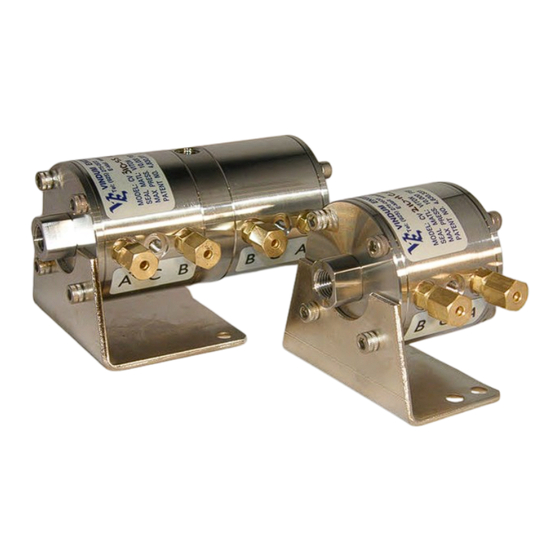
Chapter 1 1. General Overview The Vindum Engineering CV High Pressure Valves are available in two configurations; either as a 2-position, on/off valve, or a 3-way, 4-position valve. The CV Valves are air-actuated, constant-volume valves with a switching time of less than .1 second. They are typically used as switching devices in high-pressure fluid flow systems. -
Page 8: Solenoid Pilot Valve
1.4 Solenoid Pilot Valve The solenoid pilot valves for the 85 to 115 psi air supply can be operated by either: • 12 Vdc • 24 Vdc Note: The standard voltage is 12 Vdc, 24 Vdc is available on request. 1.5 Valve Temperature Rating •... -
Page 9: Additional Information
1.8 Additional Information 1.8.1 CV Valve Models CV VALVE MODELS Valve Maximum Internal Approximate Model Pressure Volume (cc) Flow Rating [PSI (Bar)] Coefficient (Cv) 2-Way On-Off Valves CV-210 10,000 (700) 0.11 CV-405 5,000 (350) 0.44 CV-410 10,000 (700) 0,44 CV-420 20,000 (1400) 0.22 3-Way 4 Position Valves... -
Page 10: Cv Valve Size
1.8.2 CV Valve Sizes Valve Size Valve Fittings Valve Model (Autoclave Engineers) Dimensions 2-Way On-Off Valves 2” diameter x 1.695” CV-210 W125 - 1/8” Speedbite (5.0 cm x 4.3 cm) 2.25” diameter x 1.95” SW250 - 1/4” Speedbite CV-405 (5.7 cm x 4.9 cm) 2.25”... -
Page 11: Chapter 2 Understanding Your Valve
Chapter 2 2. UNDERSTANDING YOUR VALVE 2.1 Principles of Operation for the 2-Way Valve Each CV 2-Way Valve contains two air supply tubes, A and B, which are connected to one solenoid-operated pilot valve. Pressurized air CV-210 Open Valve passes from the solenoid pilot valve through one of the air supply tubes into the 2-Way valve’s piston assembly. -
Page 12: Open / Closed Position (A1 / B2)
A1 C1 2.2.1 Possible Configurations of the 3-Way Valve Because the three-way CV Valve contains the equivalent of two 2-Way valves, it can be used as two independently operated on-off valves, or as a single 3-way, 4-position switching valve. The 3-way valve can be operated in the following four positions. -
Page 13: Chapter 3 Solenoid Pilot Valves & Manifolds
Chapter 3 3. Solenoid Pilot Valves and Manifolds The CV-Series Valves are completely air actuated. Air is taken into the air inlet and distributed to the solenoid pilot manifolds. The solenoid pilots then distribute and control the air flow to the valves. 3.1 Air Supply Requirements Because the CV Valves are completely air-actuated, 85 to 115 PSI of filtered air must be connected to the so- lenoid pilot valves at all times. -
Page 14: Electrical Power
The air inlet fittings on the CV Valves are plastic “quick disconnects”, the same as the outlet fittings on the solenoid pilot valves. Connect the solenoid pilot valves to the CV Valve using 1/8” nylon or Teflon™ tubing (Teflon™ tubing is used for high temperature applications). NOTE: Before any of the air lines connecting the solenoid pilot valves to the CV Valves are disconnected, for any reason, some type of numbered or color-coded tags should be placed on each air line, each solenoid pilot valve fitting, and each CV Valve fitting to ensure the correct connections are made during reassembly. -
Page 15: High Temperature Cv Valves
Figure 3-4: Normally Open CV-210 Valve In the case of the three way CV Valves, the Valves can be set to have both valves open or closed, or it can be set to have one valve remain open while the other closes. Although this configuration is not shown, set up the valve in the normally closed configuration, then swap the connections on the valve you wish to be nor- mally open. - Page 16 This page is intentionally blank.
-
Page 17: Chapter 4 Cv-200 Series & Cv-400 Series Valve Maintenance
Chapter 4 4. CV-200 Series and CV-400 Series Valve Maintenance The information contained in Chapter 4 explains how to disassemble, reassemble, and service all of the CV- series on-off valves. Chapter 5 will explain how to service the 3-way valves. The piston assemblies and sleeve assemblies in the 3-way valves are relative to those used in the on-off valves, so most of the information in his chapter also pertains to 3-way valves. -
Page 18: Disassembling The Piston Assembly
2. Use a 9/64” Allen wrench to remove the two 8-32 x 1/2” socket head cap screws [1] securing the valve to the Support Bracket [3]. 3. Remove the remaining six 8-32 x 1/2" socket-head cap screws [2] securing both End Caps [4] in place. 4. -
Page 19: Disassembling The Sleeve Assembly
4.3 Disassembling the Piston Assembly Refer to Figure 4-2, above, for the following instructions. 1. Slide two 3/4” adjustable wrenches over the flats on the outside of both the Piston halves [11] and [13]. 2. Turn either one of the Piston halves counter-clockwise, while holding the other Piston stationary with the wrench. -
Page 20: Inspecting The Sleeve And Cone
DO NOT use steel wool. If you see any scratches inside of the sleeve where the O-ring sits, a new O-ring may leak. Contact Vindum Engineering to purchase a replacement sleeve. Next inspect the cone [18, 24], which is inside of the sleeve. Check to make sure the cone has no scratches, nicks, cracks, or broken-off areas. - Page 21 1. Carefully slide the two PEEK (tan) Back-up Rings [14, 20 or 26] into both sides of the Sleeve, on top of the spacer [19 or 25] and one into the other side of the Sleeve. Press these Back-up Rings all the way down so that they are seated flat.
- Page 22 2. Apply a small amount of high quality grease (not oil) to the external O-rings [10] and the smaller internal ® O-rings [9]. Vindum Engineering uses Dow Corning 55 (M) for ambient and high temperature valves ® ® Vindum recommends Dupont Krytox for extra high temperature valves.
-
Page 23: Chapter 5 Cv-300 Series & Cv-500 Series Valve Maintenance
Chapter 5 5. CV-300 Series and CV-500 Series Valve Maintenance The information contained in Chapter 5 explains how to disassemble, reassemble and service all of the CV Series 3-way valves. 5.1 Differences Between the CV 2-Way and 3-Way Valves The 3-way CV Valve contains all of the same sub-assemblies as the 2-way CV Valve. The 3-way valve is basi- cally two 2-way valves connected in the middle with a Center Fitting [40]. -
Page 24: Disassembling The Piston Assembly
with a minimal amount of “rocking back-and-forth”. NOTE: The End Fitting is permanently attached to the End Cap with “Loctite® 272”. 5. Repeat step 4 with the other End Cap / End Fitting, and set both pairs of parts aside on a clean work sur- face. - Page 25 8. Making sure that the “cone points” are each facing AWAY FROM THE CENTER FITTING, gently slide each of the Cylinder Shell / Piston Assemblies on to the Center Fitting. 9. Using a gentle rotating motion, gently slide both End Caps completely into both ends of the Cylinder Shells.
- Page 26 This page is intentionally blank.
-
Page 27: Chapter 6 Maintenance & Troubleshooting
Chapter 6 6. Maintenance & Troubleshooting This chapter will help the user solve problems that might be encountered when operating the CV Valve. The following sections are included: • Air Supply Problems, Section 6.1 • Fluid Supply Problems, Section 6.2 •... -
Page 28: If No Light Goes On Or Off
6.1.1.2 If No Light Goes On or Off If no light goes on or off while conducting the solenoid pilot visual check, do the following: • Check that the proper voltage and the proper polarity is connected to the solenoid pilot valve(s) 6.1.2 Solenoid Pilot Valve Audio Check Listen for an “air escaping”... -
Page 29: The Air Pressure Is Too Low
3. `Check if there is any fluid in the line. 4. If the solenoid pilot valves have rusted and no longer operate, they need to be replaced. 6.1.2.3 The Air Pressure is Too Low Another cause of no “air escaping” sound when opening and closing a valve is the air pressure is too low to operate the valves. -
Page 30: Compressed Air Supply Runs Out Quickly
Verify that the gasket between the solenoid pilot valve and the air manifold is not damaged or cracked. If the gasket is cracked, contact Vindum Engineering for a replacement. If air continues to escape from the area between the solenoid pilot valve and the manifold, apply a light coat of silicone based compound (Dow –Corning Compound 111 Valve Lubricant... -
Page 31: Fluid Leaks Across A "Closed" Valve
of the Piston Assembly.) Make sure there are no scratches on the inside surface of the sleeve. If scratches are present, the sleeve must be replaced. • For the 3-way valves, also check the Center Fitting. Make sure there are no scratches on the stems of the Center Fitting. - Page 32 This Page Intentionally Left Blank...
-
Page 33: Appendix 1: Removal & Replacement Of The Cone
In the CV-405, 410, 505, and 510 series of valves, the cone must be removed with a specialized tool, available from Vindum Engineering In the CV-420 and CV-520 series of valves, however, the Cone cannot be pressed out, and if the valve seat is damaged the sleeve assembly must be replaced. - Page 34 Cone as shown below. Use the arbor press and the thin rod to push the Cone and Spacer out of the Sleeve. Cone Install Tool Cone Sleeve Figure A.1.2 Reinstalling the Cone and Spacer in the Sleeve Assembly Reinstalling the Cone and Spacer in the CV-200 and CV-300 Series of Valves Looking at the inside diameter of the Sleeve [20] from both sides, notice that on one side the inside shoul- der is “farther down”...
- Page 35 Removing the Cone and Spacer from the CV-405,410,505, and 510 Series of Valves Using a toothpick or other non-metal tool used to remove the back-up rings and O-rings from the sleeve, gently pull the spacer out of the sleeve. Unlike the CV-210 and CV-310 valves, the spacer is not press fitted into the sleeve, and should remove easily.
-
Page 36: Appendix 2: Cv-210 & Cv-310 Valve Components
APPENDIX 2 CV-210 and CV-310 Valve Components Valve Assembly - Refer to Figure 4-1 on page 11 or ( Figure 5-1) on page 17. Figure CV-210 VALVE CV-310 VALVE Description Number Quantity / Part Number Quantity / Part Number 1 & (31) Socket Head Cap Screw 8-32 x 1/2-SHSS 8-32 x 1/2-SHSS... -
Page 37: Appendix 3: Cv-405 & Cv-505 Valve Components
APPENDIX 3 CV-405 and CV-505 Valve Components Valve Assy - Refer to Figure 4-1 on page 11 or (Figure 5-1) on page 17. Figure CV-405 VALVE CV-505 VALVE Description Number Quantity / Part Number Quantity / Part Number 1 & (31) Socket Head Cap Screw 8-32 x 1/2-SHSS 8-32 x 1/2-SHSS... -
Page 38: Appendix 4: Cv-410 & Cv-510 Valve Components
APPENDIX 4 CV-410 and CV-510 Valve Components Valve Assy - Refer to Figure 4-1 on page 11 or (Figure 5-1) on page 17. Figure CV-410 VALVE CV-510 VALVE Description Number Quantity / Part Number Quantity / Part Number 1 & (31) Socket Head Cap Screw 8-32 x 1/2-SHSS / 8-32 x 1/2-SHSS... -
Page 39: Appendix 5: Cv-420 & Cv-520 Valve Components
APPENDIX 5 CV-420 and CV-520 Valve Components Valve Assembly Refer to Figure 4-1 on page 11 or (Figure 5-1) on page 17. Figure CV-420 VALVE CV-520 VALVE Description Number Quantity / Part Number Quantity / Part Number 1 & (31) Socket Head Cap Screw 8-32 x 1/2-SHSS 8-32 x 1/2-SHSS... -
Page 40: Appendix 6: Commercially Available Parts
Autoclave SMN40 CV-405, CV-410 CV-505, CV-510 Fitting Nut Autoclave AGL-40-316 CV-420, CV-520 1/8 inch Tubing Vindum .125” OD x .035” wall SS-316 Hastelloy C-276 1/4 inch Tubing Vindum SS-316 (5 – 10 kpsi) .250” OD x .065” wall Hastelloy C-276... -
Page 41: Pilot Valves / Air Manifold
A.6.2 Pilot Valves / Air Manifold Description Manufacturer Part Number Notes Pilot Valve SYJ5120-XL0Z-M5 X is 6 for 12 volt, 5 for 24 volt. Verify that number on side of pilot valve is SYJ5120 and voltage is correct. Air Manifold SYJ5-20-XX-00T XX is number of stations, 2 to 20. -
Page 42: Appendix 7: O-Ring Compatibility Chart
APPENDIX 7 O-Ring Compatibility Chart (Sourced from “Parker O-Ring® Handbook”) P = Poor F = Fair G = Good E = Excellent Butyl (-75 - 250F) Chlorinated Poly- ethylene Chloro-sulfonated Polyethylene Ethylene Propylene Flourocarbon (Viton) (-515 - 400F) Flourosilicone (-100 – 350F) Neoprene (-45 –... -
Page 43: Appendix 8: Quote Request / Order Form
APPENDIX 8 Quote Request / Order Form For CV Series High Pressure Valves Required Valve Type and Configuration Information. 2-Way Valve 3-Way Valve Select Wetted Material 316 Stainless Steel ________ ________ Hastelloy C-276 ________ ________ Expected Fluid Types Water (distilled) -
Page 44: Index
Quote Order Form ............37 Air Compressor ..........7,24,25 Request Form ..........37 Air Inlet Fittings ............8 Air Lines Numbered or Color Coded Tags ......8 Air Supply Sleeve Input and Output ..........7 Inspecting ............14 Requirements ............ 7 Sleeve &...
Need help?
Do you have a question about the CV Series and is the answer not in the manual?
Questions and answers