
Related Manuals for Rishabh RISH CON - I

Summary of Contents for Rishabh RISH CON - I
- Page 1 Operating Manual Programmable Current Transducer RISH CON - I IC 15001063 REV. C - 17/12/13...
- Page 3 Current Transducer Programmable Current Transducer Installation & Operating Instructions SectionContents Introduction Input and Output screens Programming 3.1 Programming via Front LCD & Two keys 3.1.1 Password Protection 3.1.1.1 Password verification 3.1.1.2 Editing Existing Password 3.1.2 Current Transformer parameter Setting 3.1.2.1 Current Transformer primary value 3.1.2.2...
- Page 4 3.1.6 Output characteristics Setting 3.1.6.1 Output 1 characteristics Setting 3.1.6.1.1 End value of output 1 3.1.6.1.2 Start value of output 1 3.1.6.1.3 Elbow value of output 1 3.1.6.2 Output 2 characteristics Setting 3.1.6.2.1 End value of output 2 3.1.6.2.2 Start value of output 2 3.1.6.2.3 Elbow value of output 2 Programming Via programming port available at front of Transducer using optional PRKAB600...
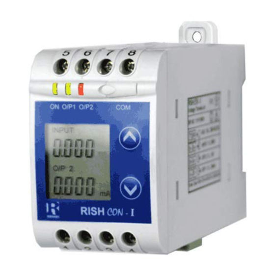
- Page 5 1. Introduction The Current Transducer is a DIN Rail/wall mounted 43.5 X 65.5mm Transducer. The Current Transducer is used to measure and convert AC Current input into proportional DC current or voltage output signal. Output signal generated is proportional to the True RMS (upto 15th Harmonic) of the input Current.
- Page 6 Table 1: Measured parameters Measured parameters Unit of Measurement Current 2. Input and Output screens In normal operation the user is presented with display test screen followed by version screen to one of the output screen. These screens may be scrolled through one at a time Output 1 or Output 2 by pressing the “...
- Page 7 Screen 5 : Current Input and Screen 6 : Current Input & Output 2 as Voltage Output 2 as Current 3. Programming Programming of transducer can be done in three ways : 3.1. Programming Via Front LCD & two keys. 3.2.
- Page 8 3.1.1. Password Protection 3.1.1.1 Password verification Password protection can be enabled to prevent unauthorised access to set-up screens, by default password protection is not enabled. Password protection is enabled by selecting a four digit number other than 0000, setting a password of 0000 disables the password protection.
- Page 9 Enter Password, second digit entered, prompt for third digit. (*Denotes that digit will be flashing). Pressing the “ Down” key will scroll the value of the third digit from 0 through to 9, the value will wrap from 9 round to 0. Pressing the “...
- Page 10 Password Incorrect. This screen is displayed when the unit has not accepted the Password entered. Pressing the " Down" key will re-enter to the “Enter Password” entry stage. Pressing the “ Up” key will exit the setup menu. 3.1.1.2 Editing Existing Password New / Change Password (*Denotes that digit will be flashing).
- Page 11 Enter New Password, second digit entered, prompting for third digit. (*Denotes that digit will be flashing). Pressing the “ Down” key will scroll the value of the third digit from 0 through to 9, the value will wrap from 9 round to 0. Pressing the “...
- Page 12 3.1.2. Current Transformer Parameter Setting 3.1.2.1 Current Transformer primary value This screen allows the user to set the CT Primary value from 1 to 9999 A. Pressing the “ Down” key will enter the “New/Change CT Primary value edit” mode. Pressing “...
- Page 13 Pressing the “ Up” key will advance the operation to the next digit and set the second digit, in this case to “0”. Enter New / Change CT Primary value, second digit entered, prompting for third digit. (*Denotes that digit will be flashing).
- Page 14 Primary value. Pressing the “ Up” key will confirm New CT Primary value & advance to the CT secondary setting (section 3.1.2.2). 3.1.2.2 Current Transformer secondary value This screen allows the user to set the CT Secondary value. Pressing the “ Down”...
- Page 15 Secondary value edit” mode. Pressing the “ Up” key will confirm the CT Secondary & advance to the Communication parameter Setting (section 3.1.3). 3.1.3. Communication Parameter Setting 3.1.3.1 Address Setting This screen applies to the RS 485 output only. This screen allows the user to set RS485 parameter for instruments.
- Page 16 from 0 through to 9, the value will wrap from 9 round to 0. Pressing the “ Up” key will advance the operation to the next digit and set the third digit, in this case to “9”. Enter New/Change Address value, third digit entered, prompting for fourth digit.
- Page 17 value through 2.4,4.8,9.6,19.2 and back to 2.4(values are flashing). Pressing “ Up” key will confirm the present value as Baud rate and advance to the Parity Selection (section 3.1.3.3). RS 485 Baud Rate confirmation Pressing “ Down” key will be re- enter into the.
- Page 18 RS 485 Parity confirmation Pressing “ Down” key will be re- enter into Parity Edit mode. Pressing the “ Up” key will set the value and advance to the Output Type selection (section 3.1.4). 3.1.4. Output Type Selection 3.1.4.1 Output 1 Type selection This screen allows the user to set the output 1 type as Voltage or Current.
- Page 19 voltage or current. Pressing the “ Down” key will enter the “output 2 type edit” mode and scroll between voltage and current. Pressing “ Up” key accepts the present type for Output 2 and advance to the Input Characteristics setting (section 3.1.5). Output 2 Type confirmation Pressing “...
- Page 20 Pressing “ Up” key will confirm the present value as End value of Input and advance to the Start value of Input setting (section 3.1.5.2). New / Change End value of Input (*Denotes that digit will be flashing). Pressing the “ Down”...
- Page 21 (*Denotes that digit will be flashing). Pressing the “ Down” key will scroll the value of the fourth digit from 0 through to 9, the value will wrap from 9 round to 0. Pressing the “ Up” key will advance to confirmation screen &...
- Page 22 depending on set value of End value of Input. Pressing the“ Up” key will advance the operation to the next digit and set the second digit, in this case to “0” Enter New / Change Start value of Input, second digit entered, prompting for third digit.
- Page 23 New/Changed Start value of Input confirmation Pressing the “ Down” key will re-enter to the "New/Changed Start value of Input edit” mode Pressing the “ Up” key will confirm New Start value of Input and advance to the Elbow function Selection (section 3.1.5.3).
- Page 24 Input selection (Section 3.1.5.4) or Output Characteristics selection (Section 3.1.6. 3.1.5.4 Elbow value of Input This screen appears only when Elbow function is enabled. This screen allows the user to set the Elbow value of the Input. The Elbow value of Input can be set between 1.5% of Set End value of Input.
- Page 25 depending on set value of End value of Input. Pressing the “ Up” key will advance the operation to the next digit and set the third digit, in this case to “1”. Enter New / Change Elbow value of the Input, third digit entered, prompting for fourth digit.
- Page 26 3.1.6 Output Characteristics Setting 3.1.6.1 Output 1 Characteristics Setting 3.1.6.1.1 End value of output 1 This screen allows the user to set the End value of Output 1, (considerd as DC Current). The End value of Current Output is fixed at 20mA. Pressing the “...
- Page 27 New / Change Start value of the Output 1 (*Denotes that digit will be flashing). Pressing the “ Down” key will not affect the first digit It always remains 0. Pressing the “ Up” key will advance the operation to the next digit and set the first digit in every case to ‘0’.
- Page 28 on the set End value of Output. Pressing the “ Up” key will advance the operation to the next digit and set the third digit, in this case to “0”. Enter New / Change Start value of the Output 1, third digit entered, prompting for fourth digit.
- Page 29 Pressing the “ Down” key will enter the“ New/Change Elbow value of the Output1 edit” mode. Up” key will set the Pressing “ present value as Elbow value of the Output 1 and advance to the Output 2 Characteristics setting (section 3.1.6.2). New / Change Elbow value of the Output 1 (*Denotes that digit will be flashing)
- Page 30 Enter New / Change Elbow value of the Output 1, second digit entered, prompting for third digit. (*Denotes that digit will be flashing). Pressing the “ Down” key will scroll the value of the third digit from 0 through to 9, the value willwrap from 9 round to 0 depending on the set End value of Output.
- Page 31 Pressing the “ Up” key will confirm New Elbow value of the Output 1 and advance to the Output 2 Characteristics setting (section 3.1.6.2). 3.1.6.2 Output 2 Characteristics selection 3.1.6.2.1 End value of output 2 This screen allows the user to set the End value of Output 2, (considerd as DC Voltage).
- Page 32 New / Change Start value of the Output 2 (*Denotes that digit will be flashing).Pressing the “ Down” key will not affect the value of first digit, it is always 0. Pressing the “ Up” key will advance the operation to the next digit and set the first digit, in every case to “0”.
- Page 33 Enter New / Change Start value of the Output 2, third digit entered, prompting for fourth digit. (* denotes that digit will be flashing). Pressing the “ Down” key will scroll the value of the fourth digit from 0 through to 9, the value will wrap from 9 round to 0.
- Page 34 Pressing the “ Down” key will enter the “New/Change Elbow value of the Output 2 edit” mode. Pressing “ Up” key will confirm the present value as Elbow value of the Output 2 and exit setup menu. New / Change Elbow value of the Output 2 (*Denotes that digit will be flashing).
- Page 35 entered, prompting for third digit. (*Denotes that digit will be flashing). Pressing the “ Down” key will scroll the value of the third digit from 0 through to 9, the value will wrap from 9 round to 0 depending the set End value of Output. Pressing the “...
- Page 36 Programming Via Programming port available at front of Transducers using optional PRKAB60 Adapter For programming of transducer, steps to be followed are Step 1 : DIP Switch setting DIP Switches should configure for desired Output type as per given in section 3.3.1 Step 2 : programming A PC with RS 232 C interface along with the programming cable PRKAB60 and the configuration software are required...
- Page 37 3.3 Programming Via optional RS485 (MODBUS) communication port. (Refer section 4 for programming through MODBUS) 3.3.1: DIP Switch Setting for Changing Output type The Transducer output type can be changed from DC current to DC voltage depending upon user requirement on site.
- Page 38 Switches of Output 2,can be set for desired Output type Voltage or Current. Switches of Output 1,can be set for desired Output type Voltage or Current.
- Page 39 5) After changing the switches for desired Output, Insert the front cover. Insert the front cover, press in direction of arrow. 6) After inserting the front cover insert the Interface card PCB and back cover.. Insert the Interface card PCB and Back cover, press in direction of arrow.
- Page 40 4. RS 485 ( ModBus ) Current Transducer supports MODBUS (RS485) RTU protocol( 2-wire )Connection should be made using twisted pair shielded cable. All "A" and "B" connections are daisy chained together. The screens should also be connected to the “Gnd” terminal. To avoid the possibility of loop currents, an Earth connection should be made at one point on the network.
- Page 41 The each byte in RTU mode has following format 8-bit binary, hexadecimal 0-9, A-F 2 hexadecimal characters contained in each 8- bit field of the message Format of 4 bytes (32 bits) per parameter. Data Floating point format ( to IEEE 754) Most Bytes significant byte first (Alternative least significant byte first)
- Page 42 Illegal function The function code is not supported by Current Transducer. Illegal Data Attempt to access an invalid address Address or an attempt to read or write part of a floating point value Illegal Data Attempt to set a floating point variable Values to an invalid value 4.1 Accessing 3 X register for reading measured...
- Page 43 Start Address High : Most significant 8 bits of starting address of the parameter requested. Start Address low : Least significant 8 bits of starting address of the parameter requested Number of register Hi: Most significant 8 bits of Number of registers requested.
- Page 44 Table 2 : 3 X register addresses (measured parameters) Modbus Start Address Parameter Address Hex Parameter (Register) High Byte Low Byte 30007 Current 4.2 Accessing 4 X register for Reading & Writing Each setting is held in the 4X registers .ModBus code 03 is used to read the current setting and code 16 is used to write/change the setting.
- Page 45 Number of register Hi : Most significant 8 bits of Number of registers requested. Number of register Lo : Least significant 8 bits of Number of registers requested. (Note : Two consecutive 16 bit register represent one parameter.) Response: Device address ( 1 ) Device Address 01 (Hex) Function Code...
- Page 46 (Note : Two consecutive 16 bit register represent one parameter.) Example : Writing Device address Device address : Start address = 0E (Hex) Number of registers = 02 Query:( Change Device address to 2) Device Address 01 (Hex) Function Code 10 (Hex) Starting Address High 00 (Hex)
- Page 47 Data register 2 Low Byte : Least significant 8 bits of Data register 2 of the parameter requested. (Note: Two consecutive 16 bit register represent one parameter.) Response Device Address 01 (Hex) Function Code 10 (Hex) Start Address High 00 (Hex) Start Address Low 0E (Hex) Number of Registers Hi...
- Page 48 Para- Modbus Start Address Hex Address Parameter Read / meter (Register) High Byte Low Byte Write 40007 40009 CT Primary R/Wp 40011 CT Secondary R/Wp 40013 R/Wp 40015 Device address RS 485 Setup R/Wp 40017 R/Wp 40019 Password 40021 40023 40025 Sim_Output A 40027...
- Page 49 This address is used to set the Device Device 40015 Address between 1 to 247. Adress This address is used to set the Baud RS 485 40017 rate, Parity, No of Stop bits. Setup This address is used to set & reset the password.
- Page 50 Baud Rate Parity Stop Bit Decimal value 9600 NONE 9600 EVEN 9600 4800 NONE 4800 NONE 4800 EVEN 4800 2400 NONE 2400 NONE 2400 EVEN 2400 Note : Codes not listed in the table above may give rise to unpredictable results including loss of communication. Exercise caution when attempting to change mode via direct Modbus writes.
- Page 51 Caution In the interest of safety and functionality this product must be installed by a qualified engineer, abiding by any local regulations. Voltages dangerous to human life are present at some of the terminal connections of this unit. Ensure that all supplies are de-energised before attempting any connection or disconnection.
- Page 52 has been designed to automatically recover in the event of a high level of transients. In extreme circumstances it may be necessary to temporarily disconnect the auxiliary supply for a period of greater than 5 seconds to restore correct operation. The Current inputs of these products are designed for connection in to systems via Current Transformers only, where one side is grounded.
-
Page 53: Specifications
within easy reach of the OPERATOR & It shall be marked as the disconnecting device for the equipment. 5.5 Fusing It is recommended that all voltage lines are fitted with 1 amp HRC fuses. 5.6 Earth/Ground Connections For safety reasons, CT secondary connections should be grounded in accordance with local regulations. - Page 54 Auxiliary AC/DC Auxiliary Supply 60V….300 VAC-DC ±5% 24V….60 VAC-DC ±10% Auxiliary Supply 40..65 Hz frequency range Auxiliary Supply consumption VA for one output £ 60V…….300 VAC-DC 10VA for two outputs £ VA for one output £ 24V…….60 VAC-DC 6VA for two outputs £...
- Page 55 Accuracy : ( Acc. to IEC 60688) Reference Value Output end Value Y2 (Voltage or Current) Basic Accuracy 0.2*C Factor C (The Highest value applies) Linear characteristics Bent characteristics Y1 - Y0 or C=1 X1 - X0 or C=1 or C=1 Output characteristics 1) Example of setting with Linear characteristics...
- Page 56 2) Example of setting with Bent characteristics: X0 = Start value of input Y0 = Start value of output X1 = Elbow value of input Y1 = Elbow value of output X2 = End value of input Y2 = End value of output R = Rated value of I = Nominal input current .
- Page 57 Additional Error Temperature influence ± 0.2% /10°C Influence of Variations: As per IEC EN-60688 standard. Output stability < 30min Safety Protection Class II (Protection Isolated, EN 61010) Protection IP 40, housing according to EN 60 529 IP 20,terminal according to EN 60 529 IP Pollution degree Installation Category III Insulation Voltage...
-
Page 58: Connection Diagram
Environmental Nominal range of use 0 °C...23 °C... 45 °C (usage Group II) Storage temperature -40 °C to 70 °C Relative humidity of < 75% annual mean Altitude 2000m max Location Indoor use Ambient tests EN 60 068-2-6 Vibration Acceleration ±... - Page 59 Input I 5 6 7 8 1 2 3 4 (Optional) Output-1 Output-2...
- Page 60 Meaning of symbols on the instrument Warning concerning a point of danger (Attention:observe documentation) Equipment protected throught by Double insulation or reinforced insulation DC voltage /Current AC/DC voltage Isolation between input versus all other circuit is 3.7 KV.
- Page 61 Notes...
- Page 62 Notes...
- Page 63 Notes The Information contained in these installation instructions is for use only by installers trained to make electrical power installations and is intended to describe the correct method of installation for this product. However, Manufacturer has no control over the field condition which influence product installation.
- Page 64 Notes...
- Page 65 Notes RISHABH RISHABH INSTRUMENTS PVT. LTD. F-31, M.I.D.C., Satpur, Nashik 422 007, India. Tel. : +91 253 2202162, 2202202, INSTRUMENTS Fax : +91 253 2351064 Email : marketing@rishabh.co.in Measure, Control & Record with a Difference www.rishabh.co.in...
Need help?
Do you have a question about the RISH CON - I and is the answer not in the manual?
Questions and answers