
Related Manuals for Stanadyne DE

Summary of Contents for Stanadyne DE
- Page 1 Model DE Electronically Controlled Diesel Fuel Injection Pump Operation and Instruction Manual...
- Page 3 CONTENTS GENERAL A. Purpose of the Manual B. Model Number System C. General Information SECTION 1 CONSTRUCTION AND OPERATION A. Components and Function B. Electrical Circuitry C. Fuel Flow D. Transfer Pump E. Transfer Pump Regulator F. Charging G. Discharging, Spill-Pump-Spill H.
- Page 5 Stanadyne DE electronic diesel fuel 5780 injection pump. In addition to this manual a. DE = D series pump, E electronic all special tools and test equipment as out- b. 2 = two pumping plungers lined herein are needed plus all service c.
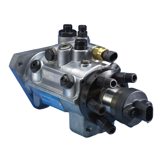
- Page 6 Fig. 1.1 A. Components and Functions (Figure 1.1) In the DE pump Shown in Figure 1.1, the drive The main components of the DE pump are shaft is supported at both ends by needle bear- pictured above in Figure 1.1. They include: ings and carries the two cam roller shoes and 1.
- Page 7 When the ECM pro- B. Electrical Circuitry (Figure 1.2 and 1.3) gram determines that the engine has received The DE pump only incorporates one sensor, a the correct amount of fuel, the current to the thermistor that provides the Engine Control solenoid is interrupted allowing the poppet valve Module (ECM) with fuel temperature data.
- Page 8 Housing Pressure Injection Pressure Lube Oil speed. The DE pump has no built-in governor. Gover- nor regulation, high and low idle speeds, throttle Pressurized fuel then flows from a transfer progression and injection timing are all sensed pump porting screw through a passage on...
- Page 9 retainer. Since the inside diameter of the At high speeds the charging accumulator liner is eccentric to the drive shaft axis, ro- adds its volume of fuel to the volume of tation of the shaft, blade retainer and transfer pump supplied fuel insuring com- blades results in the blades moving up and plete pumping plunger charging.
- Page 10 A small drilling in the face of the porting DE and DS pumps as opposed to the other plate allows transfer pressure to flow into D series pumps where the pressure is the counter bore in the blade carrier where regulated prior to flowing through the pump.
- Page 11 F. Charging (Figure 1.8, 1.9, 1.10 and With the DE pump the pumping chamber 1.11) is filled completely between each injection regardless of the quantity of fuel to be in- As the drive shaft and rotor rotate, fuel un- jected into the engine.
- Page 12 G. Discharging, Spill – Pump – Spill nozzle. The Pump portion of the discharge (Figures 1.9, 1.10, and 1.11) event ends when the ECM de-energizes the fuel control solenoid allowing the pop- Spill Power Off...
- Page 13 J. Dynamic Pump Timing Ad- vancement (Figure 1.13 and Fuel fills the DE pump housing due to leak- 1.14) age of transfer pump pressure plus injec- In all pump-line-nozzle fuel injection sys-...
- Page 14 For example, instead of ent injection lag. starting at 12 degrees it now starts at 10 With the DE pump models however, both degrees. Now the injection pump is start- timing and delivered fuel quantity can be...
- Page 15 ECM sets the number of counts (degrees) for the second counter. The second clock controls when the pump- ing event ends by counting off an ECM de- termined amount of engine degrees before turning off the power to the pump solenoid, ending the pumping event by starting the second spill event.
- Page 16 Fig. 1.14...
- Page 17 SECTION 2 - DISASSEMBLY 31213 T-40 Torx Bit Study the manual first. Before commencing with the disassembly of the pump, cover the fuel in- 31214 1/4” Drive Handle let, fuel outlets, and the return line connector and 31215 Seal Protection Tube wash the pump with solvent and blow dry with 33038 40 IPR Torx Bit...
- Page 18 Step 1. Mount the pump in the 19965 pump holding fixture and clamp in a vise with the pump right side up. Fig. 2.3 Step 4. Loosen and remove the vent assem- bly screw using a T-40IPR bit. Discard the seal- Fig.
- Page 19 Step 6. With a 5/8’ wrench loosen and re- move the transfer pump regulator plug. Remove and discard the o-ring seal. Fig. 2.8 Step 9. Loosen and remove the timing ac- cess hole plug using a 1/4” hex driver. Remove and discard the o-ring seal.
- Page 20 Step 11. Remove the inlet filter and transfer Step 12. Using a T-10 bit, loosen and remove pump insert retaining spring. Remove the the fuel control locking screw and plate from the Transfer pump insert by pulling straight up on hydraulic head assembly.
- Page 21 Step 14. Loosen and remove the transfer Step 17. Invert the pump and holding fixture in pump pressure tap screw from the head lock- the vise and tip the pump forward so that the ing screw using a T-40 bit. Remove and dis- drive shaft is facing straight down.
- Page 22 Step 19. Remove 2 sets of shoes and cam Step 21. Remove the cam ring from the hous- rollers from the housing. ing. Fig. 2.19 Step 20. Using a 5/8” socket, loose and re- move the cam pin screw. Remove and discard Fig.
- Page 23 Step 25. Using retaining ring pliers 20044 to Step 23. Loosen and remove the transfer expand and carefully remove the retaining ring pump locking screw using a 1/2” socket. from the drive shaft. Be sure to expand the ring sufficiently and guide it so as not to contact and possibly damage the surface of the drive shaft that the seals ride on.
- Page 24 Fig. 2.28 Step 29. Remove the transfer pump liner, blades and blade spring as an assembly. Sepa- Fig. 2.26b rate the blades and spring from the liner. Step 27. Loosen and remove 7 transfer pump porting plate screws using a T-10 bit. Fig.
- Page 25 Step 30 Lift the blade retainer off the drive shaft and remove the woodruff key from the shaft. Fig. 2-32 Step 33 Using the brass hook, 13301 remove the 2 rotor plungers from the rotor. NOTE: Do not remove the set screw from the drive end of the rotor –...
- Page 26 Step 35 While holding the solenoid in one hand loosen and remove the 4 armature cover retaining screws using a T-10 bit. Remove the armature cover retainer. Fig. 2-37 Step 38 Remove the armature pin assembly from the fuel control solenoid. Do not disas- semble the armature pin from the plate –...
- Page 27 Step 39 Remove the adjustable spacer re- finished surfaces. tainer and adjustable spacer (crush washer) from the hydraulic head. Discard the adjustable spacer. Fig. 2-41 Fig. 2-39 Step 42 Remove poppet valve, poppet valve Step 40 Remove the 2 rotor retainer locating spring and poppet valve shims.
- Page 28 Fig. 2-43 Fig. 2-45 Step 46 Remove 2 accumulator piston stops Step 44 Remove the 4 snubber plate assem- and springs. Remove 2 accumulator pistons. A blies. 2-inch long 6-32 screw may be helpful for this. Fig. 2-46 Step 47 Clamp pump holding fixture 19965 with pump housing mounted to it in vise and drive end facing straight up.
- Page 29 Step 49 Rotate the outer nut clockwise using the 9/16” wrench to pull the 2 drive shaft seals and the bearing all together. NOTE: Consider- able force may be required to start all parts moving in the bore. Fig. 2-47 Step 48 While using a 9/16”...
- Page 30 29660 0.028 protect his equipment. NOTE: The illustrations that follow depict typical locations where com- ponent wear might be observed in DE pumps. 29661 0.0305 Damage and wear is not limited to these ar- eas nor is the wear shown meant to indicate that these parts require replacement.
- Page 31 the transfer pump group, cam ring and head and key for damage and replace as necessary. rotor assembly fit for erosion, wear or cracks. 2. Distributor Rotor (Fig. 3.1) – Examine the shank of the rotor for wear or erosion around Fig.
- Page 32 6. Transfer Pump Liner (Fig. 3.5) – Inspect wear, nicks or chips at the edges. Replace the the inside diameter of the transfer pump liner rollpin if damaged or missing. Inspect the area for unusually heavy scoring. where the drive shaft seals ride. Wear bands in these areas are considered normal and do not warrant shaft replacement.
- Page 33 SECTION 4 - REASSEMBLY Step 1 Place pump housing on the arbor press with the mounting flange facing upwards. Drop the fuel side drive shaft seal into the drive shaft bore of the housing with the seal lip facing down. Do not lubricate seal or housing bore at this time.
- Page 34 Step 4 Press seal in until the tool bottoms on the housing. Fig. 4.5b Step 6 Install the bearing retainer onto the drive shaft so that the sealing ring will be facing Fig. 4.4 up. Install a new o-ring seal and then the seal- Step 5 Remove collar from the 33421 tool.
- Page 35 Step 7 Apply a small amount of Lubriplate Step 9 Place the transfer pump liner, with the grease to the woodruff key: then install the woo- arrow facing down, onto the inner bearing re- druff key into its cutout in the drive shaft. tainer.
- Page 36 Step 11 Squeeze the transfer pump blade Step 13 Install the 7 transfer pump assembly spring and insert it between the blades and re- screws finger tight. DO NOT tighten screws at tainer. this time. Step 14 Place the clamping ring of the 30855 compression tool around the transfer pump as- sembly and install the 30855 pliers.
- Page 37 Step 17 Orient the transfer pump assembly group retaining ring with the sharp edge facing upwards. Using retaining ring pliers 20044, ex- pand the retaining ring and carefully slide it down the shaft into its groove. NOTE: Exercise ex- treme care not to allow contact possibly scratching the drive shaft in the area where the seals ride.
- Page 38 Step 19 Remove the protection tube from the shaft and install the transfer pump porting plate locking screw on the underside of the pump fin- ger tight . Fig. 4.19 Step 20 Assemble new seals onto the trans- Fig. 4.20b fer pump insert and lubricate with Lubriplate grease.
- Page 39 Step 22 Install the transfer pump porting plate screw and tighten to 140–160 lbf-inches (16.0- 18 N-m) using a 3/16” hex bit. Fig. 4.24 Step 25 Insert the two rotor retainer locating Fig. 4.22 pins into the head assembly. Step 23 Using a 1/2” socket, tighten the port- ing plate locking screw on the underside of the pump to 220-240 lbf-inches (25-27N-m).
- Page 40 ger, insert the two rotor retainers with the cham- removed. See the Part Inspection Section and fered side down into the groove adjacent to the the individual specification for replacement shim poppet valve seat area of the rotor. thickness, part numbers and configuration. In- stall the shims into the poppet valve bore en- suring that they are properly seated at the bot- tom of the bore.
- Page 41 Step 30 Install poppet valve, notched end Step 32 Install a new adjustable spacer (crush down, into its bore in the rotor, making sure to washer) into the counterbore of the adjustable engage the notch in the valve with the cross pin spacer retainer.
- Page 42 Step 34 Install an outer bushing, new seal, and an inner bushing onto each terminal stud. Lubricate the seals with Lubriplate grease and assemble the two terminal stud assemblies to the armature cover. Fig. 4.35b Step 36 Orient the armature cover retainer Fig.
- Page 43 Fig. 4.36b Fig. 4.38 Step 39 Install accumulator retaining screw Step 37 Thread the fuel control solenoid as- plugs to bores and tighten to 90-110 lbf-inches sembly into the hydraulic head hand tight. (10-12 N-m) using a 3/16” hex bit. Fig.
- Page 44 Fig. 4.40 Fig. 4.42 Step 41 Using the 30853 armature cover spanner wrench slowly begin rotating the sole- noid assembly clockwise as viewed from the Step 43 Install the fuel control solenoid lock- fuel line connector end of the hydraulic head to ing plate and retaining screw to the hydraulic tighten the solenoid down against the adjust- head.
- Page 45 Fig. 4.44 Step 45 Tilt vise so that the drive shaft is pointing straight down. Install the cam ring, ar- row side up, into the housing and position with Fig. 4.45b the cam locating screw hole facing the top of the pump.
- Page 46 Step 47 Carefully align the dot on the rotor drive tang with the alignment dot on the drive shaft and install the head and rotor assembly into the housing lining up the head locking and locating screw holes. Fig. 4.48 Step 49 Using protection tube 31215, as- semble two new seals to the head locating screw and lubricate with Lubriplate grease.
- Page 47 Step 50 Assemble two new seals to both Step 52 Tighten the head locking screw on head locking screws and lubricate with the regulator side to 180-220 lbf-inches (20-25 Lubriplate grease. Install the screw which incor- N-m) using a 3/4” socket. porates the transfer tap and has a 3/4”...
- Page 48 Step 54 Install the vent wire assembly into the Step 56 Install a new seal on the transfer hydraulic head. Tighten to 25-30 lbf-inches (3- pump tap screw and install the plug into the head 3.5 N-m) using a 1/8” hex bit. Five different vent locking screw hand tight.
- Page 49 Step 60 Assemble two new seals to the trans- Step 62 Place the transfer pump insert spring fer pump pressure regulator and lubricate with and then the inlet filter into the hole on top of the Lubriplate grease. Install the regulator to the housing.
- Page 50 Step 64 Assemble a new seal to the return Step 66 Install a new seal to the temperature line connector/housing pressure regulator and sensor and install into the housing. Tighten to install into the housing. With a 9/16” deep socket 120-160 lbf-inches (13-18 N-m).
- Page 51 36951 Low Dead Volume Calibrating Injectors, 6.5L apllications. having a factory set opening pressure of 250 bar/3500 p.s.i. Step1. Clamp the test bench 19965 pump hold- ing fixture in a suitable vise and mount the DE Part pump to the fixture. Number Description 33497 Transfer Pump Pressure Tap Step 2.
- Page 52 Fig. 5.3 Step 6. Using a suitable 6.2/6.5L test bench drive adaptor, align the pin and holes with the DE pump drive adaptor. Install the mounting bolts and tighten to the test bench manufac- turers recommended torque value. Step 4. Install the drive adaptor assembly onto the pump drive shaft.
- Page 53 ing pressure gage supply line to the 36464 Housing Pressure Tap. Step 12. Loosen the two positioning screws on the top of the sensor bracket. Adjust the Hall effect sensor, placing the center of the sensor in line over the center of the toothed wheel.
- Page 54 (large tube) and the return oil line to the return oil fitting (smaller tube). Step 16. Connect the wire harness for the 36269 DE Calibration Package. C. Special Test Bench Removal Instructions Disassemble the drive and mounting hardware in the reverse order that was described in Test Bench Mount- ing Instructions.
- Page 60 Fax: (860) 683-4581 Fax: 39.030.2731610 Stanadyne Corporation 26-30 Avenue des Freres Lumiere 78190 Trappes France Tel: 33.1.34.82.24.24 Fax: 33.1.34.82.24.20 Stanadyne Corporation 92 Deerfield Road, Windsor, CT 06095, U.S.A. Tel: (860) 525-0821; Fax: (860) 683-4581; www.stanadyne.com 99820 Printed in U.S.A. 1/08...
Need help?
Do you have a question about the DE and is the answer not in the manual?
Questions and answers