
Summary of Contents for Canalta Combustex BMS-2000
- Page 1 I N S T A L L A T I O N O P E R A T I O N S M A N U A L The Combustex BMS-2000 B149.3 Compliant Burner Mangagement System BMS Software Version 5.03...
- Page 2 QUALITY, RELIABILITY, PERFORMANCE With Control Comes Safety BMS-2000 Burner Management System gives you the automated control to safely start, monitor and manage a single or dual burner gas-fired industrial heater. • Calibrate, tune and configure more than 60 parameters and variables via the front keypad. •...
- Page 3 The Combustex BMS-2000 Burn e r M a n a g eme nt Sys te m O P E R A T I O N S M A N U A L C o n t r o l l e r V e r s i o n 5 . 0 3...
-
Page 4: Table Of Contents
Combustex BMS-2000 [5.03] Operations Manual of 42 CONTENTS 1. INTRODUCTION 1.1 Overview 1.2 Burner Sequencing 1.3 ESD (Emergency Shutdown) Capabilities 1.4 Temperature Control 1.5 Features 1.6 Communications 1.7 Definitions of Common Terms and Abbreviations 1.8 Technical Specifications 2. OPERATION 2.1 Overview 2.2 Passwords - Gaining Entry... -
Page 5: Combustex Bms-2000 [5.03] Operations Manual 2 Of
BMS, allowing the BMS to light and maintain a pilot flame using the sensor that is incorporated into the pilot ignition module, providing flame verification. The Combustex BMS-2000 is suitable for both new installations and retrofitting older vessels, and is not limited to Pilot Pro™ igniters. -
Page 6: Burner Sequencing
Combustex BMS-2000 [5.03] Operations Manual - 1. INTRODUCTION of 42 1.2 BURNER SEQUENCING When initiating a start sequence, the BMS will open the pilot and energize the igniter for the trial for ignition period and wait for the flame sensor to confirm a flame. Upon flame verification, the unit will then go into “Normal Operation”. -
Page 7: Temperature Control
Combustex BMS-2000 [5.03] Operations Manual - 1. INTRODUCTION of 42 1.4 TEMPERATURE CONTROL The BMS-2000 can be configured to perform bath temperature control by a Proportional or ON/OFF Control output. Proportional Control: One 4-20mA output will be used. Set point and PID parameters are configurable via the BMS-2000 keypad. -
Page 8: Communications
42 1.6 COMMUNICATIONS The Combustex BMS-2000 includes both analog (9 total) and digital (28 total) connections for communication between the BMS controller and various combustion system monitoring and control devices. In addition, the BMS offers Modbus connectivity for fast, robust communication between the BMS unit and remote controllers and readout devices. -
Page 9: Operation
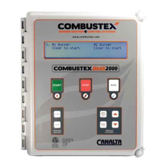
Combustex BMS-2000 [5.03] Operations Manual - 2. OPERATION of 42 OP ER ATI ON 2.1 OVERVIEW The operator interface of the BMS-2000 consists of two components: • Heated, Back-lit LCD Alphanumeric Display • 9-Key Membrane Keypad Auto Backlight Sensor LCD Display... - Page 10 Combustex BMS-2000 [5.03] Operations Manual - 2. OPERATION of 42 • CONFIG allows the user access to the Configuration Menu. Note: BMS must be shut down (not in NORMAL OPERATION) in order to access the Configuration Menu. Note: Configuration Menu is password protected.
-
Page 11: Passwords - Gaining Entry
Combustex BMS-2000 [5.03] Operations Manual - 2. OPERATION of 42 Pages are displayed in the following order: Page 1 - Sequence Status & Shutdown Page 2 - Temperature Control / Set Point Page 3 - Output Status Page 4 - Auxiliary Analog Input Page 5 - PID &... -
Page 12: Sequence Status & Shutdown Annunciation
Combustex BMS-2000 [5.03] Operations Manual - 2. OPERATION of 42 2.3 SEQUENCE STATUS & SHUTDOWN ANNUNCIATION Page one on the controller display is the Sequence / Status page which displays: • The current status of the controller • Shutdown conditions All shutdowns are recorded in chronological order and can be scrolled through. - Page 13 Combustex BMS-2000 [5.03] Operations Manual - 2. OPERATION of 42 The BMS-2000 is now ready to relight the burner. The following message appears after depressing the ‘START’ button (ignitor is on Preset Trial for Ignition Period): Ignition ON The following message is displayed once the system has verified the pilot flame:...
-
Page 14: Temperature Control
Combustex BMS-2000 [5.03] Operations Manual - 2. OPERATION of 42 2.4 TEMPERATURE CONTROL Temperature control is accessed on page two of the BMS-2000 controller display. This page displays: • Bath and/or Process Temperature • Bath and/or Process Set Point •... -
Page 15: Output Status
Combustex BMS-2000 [5.03] Operations Manual - 2. OPERATION of 42 2.5 OUTPUT STATUS PAGE Page three of the BMS-2000 controller displays the status of the following: • Pilot Solenoid Valve • Main Solenoid Valve • Ignition Output • Purge Blower Output... -
Page 16: Pid & Control Parameters
Combustex BMS-2000 [5.03] Operations Manual - 2. OPERATION of 42 2.7 PID & CONTROL PARAMETER PAGE NOTE: This page is password protected. See section 2.2. Page five of the BMS-2000 controller display allows the adjustment of four parameters relating to temperature control: •... -
Page 17: Overview
Combustex BMS-2000 [5.03] Operations Manual - 3. CONFIGURATION of 42 CONF IGUR ATION 3.1 OVERVIEW The BMS-2000 Burner Management System is configured by adjusting a series of password protected menu items. This menu is accessed by depressing the ‘CONFIG’ key on the BMS keypad. -
Page 18: Configuration Menu Options
Combustex BMS-2000 [5.03] Operations Manual - 3. CONFIGURATION of 42 3.2 CONFIGURATION MENU ITEMS Below are the BMS-2000 Version 5.03 CONFIG menu items and their options. See pp. 17 - 23 for a description of each. Item # Sequencing Items... - Page 19 Combustex BMS-2000 [5.03] Operations Manual - 3. CONFIGURATION of 42 Configuration Menu Items cont’d Item # Sequencing Items Available Options Notes Fuel Pressure #2 None / Hi Press / Hi & Low Press None / Indicate Only / Spare Temp. T/C #1 0 - 800°C (32 - 1472°F)
- Page 20 Combustex BMS-2000 [5.03] Operations Manual - 3. CONFIGURATION of 42 Burners 1 / 2 / Dual Parallel / Dual Series • Burner 1 operates only (see P&ID drawings pp. 31 - 15). • Burner 2 operates only. • Parallel - Dual Burner System. Both burners will run independently of each other •...
- Page 21 Combustex BMS-2000 [5.03] Operations Manual - 3. CONFIGURATION of 42 Flame T/C 2nd Level Timer 0 - 5.0 Minutes This value sets the amount of time the BMS will allow for the flame to reach the second set point. The ignition sequence is halted if the flame fails to reach the second set point in this time.
- Page 22 Combustex BMS-2000 [5.03] Operations Manual - 3. CONFIGURATION of 42 Remote Stop Yes / No If enabled, this momentary input is used to remotely shut down the BMS-2000. Most commonly used as an ESD input. Power Failure Relight Yes / No If enabled, the unit will automatically relight when the power is restored after failure.
- Page 23 Combustex BMS-2000 [5.03] Operations Manual - 3. CONFIGURATION of 42 Fuel High Pressure #1 Yes / No Enables this contact to be used as a shutdown. Fuel Pressure #2 None / Hi Press / Hi & Low Press Two contact inputs are available for shutdown purposes. These are tagged as “High Fuel Pressure #2” and “Low Fuel Pressure #2”.
- Page 24 Combustex BMS-2000 [5.03] Operations Manual - 3. CONFIGURATION of 42 Control Mode Proportional / On-Off / None • Proportional: The unit will output a 4-20mA loop for the purpose of temperature control. • On-Off: The unit will cycle the main burner(s) to maintain temperature.
- Page 25 Combustex BMS-2000 [5.03] Operations Manual - 3. CONFIGURATION of 42 Control Output Mode Steady / Latching Pulse This sets the output mode for the pilot and main solenoid valves. • Steady: Provides a constant voltage to the solenoid when on.
- Page 26 Combustex BMS-2000 [5.03] Operations Manual - 3. CONFIGURATION of 42 L.P. Filter (Pilot, Spare #1) 0 - 9999 This sets the filter, which mathematically smooths noisy signals for the pilot and spare thermocouple input. L.P. Filter (Pilot, Spare #2) 0 - 9999 This sets the filter, which mathematically smooths noisy signals for the bath and process thermocouple input.
-
Page 27: Overview
Combustex BMS-2000 [5.03] Operations Manual - 4. CALIBRATION of 42 C A LIBR ATION 4.1 OVERVIEW NOTE: This page is password protected and cannot be accessed while the BMS is in normal operation. See section 2.2. The BMS-2000 calibration menu is accessed by depressing the ‘CALIB. ’ button on the controller’s keypad. -
Page 28: Calibration Menu Items
Combustex BMS-2000 [5.03] Operations Manual - 4. CALIBRATION of 42 4.2 CALIBRATION MENU ITEMS Inputs Range Allowed / Type of Signal Pilot #1 Flame Zero Value 0 - 800°C (32 - 1472°F) / Type K Thermocouple Input Pilot #1 Flame Span Value 0 - 800°C (32 - 1472°F) / Type K Thermocouple Input... -
Page 29: Thermocouple / Mv Reference Chart
Combustex BMS-2000 [5.03] Operations Manual - 4. CALIBRATION of 42 4.3 THERMOCOUPLE REFERENCE CHART THERMOCOUPLE TO MILLIVOLTAGE REFERENCE CHART THERMOCOUPLE TO MILLIVOLTAGE REFERENCE CHART Thermocouple Type K Thermocouple Type K Thermocouple Type K Thermocouple Type K Temp. (°F) Voltage (mV) Temp. -
Page 30: Installation
Combustex BMS-2000 [5.03] Operations Manual - 5. INSTALLATION of 42 IN S TA LL ATION 5.1 OVERVIEW Controller Location The BMS-2000 is CSA certified for Class 1, Division 2 Groups A, B, C and D hazardous locations. It is also rated NEMA Type 4x and can be readily installed outdoors. -
Page 31: Analog Input Connections
Combustex BMS-2000 [5.03] Operations Manual - 5. INSTALLATION of 42 5.2 ANALOG INPUT CONNECTIONS Five type K thermocouple inputs are available: 1. Pilot Flame #1 (N/A if using contact input for flame sensing) 2. Pilot Flame #2 (N/A if using contact input for flame sensing) 3. -
Page 32: Analog Output Connections
Combustex BMS-2000 [5.03] Operations Manual - 5. INSTALLATION of 42 5.5 DIGITAL OUTPUT CONNECTIONS Sixteen digital outputs are available: 1. Igniter #1 2. Igniter #2 3. Status #1 4. Status #2 5. Pilot #1 6. Pilot #2 7. Main #1 SD Valve 8. -
Page 33: Sample P&Id Drawings & Wiring Diagrams
Combustex BMS-2000 [5.03] Operations Manual - 5. INSTALLATION of 42 DIAGR AM S BMS 2000 Wiring Diagram - Version 5.03 / 5.032 FIELD DEVICES SOLENOID OUTPUTS Note: jumper out N/C eld devices not in use. SOV. FLAME DETECTION (BURNER #2) MAIN #1 SHUTDOWN VALVE SOV. - Page 34 Combustex BMS-2000 [5.03] Operations Manual - 5. INSTALLATION of 42 For operational, technical or installation assistance, please contact us. Phone: 403.342.4494 Web: www.canaltaflow.com Call Us Toll Free: 1-855-226-2582...
- Page 35 Combustex BMS-2000 [5.03] Operations Manual - 5. INSTALLATION of 42 For operational, technical or installation assistance, please contact us. Phone: 403.342.4494 Web: www.canaltaflow.com Call Us Toll Free: 1-855-226-2582...
- Page 36 Combustex BMS-2000 [5.03] Operations Manual - 5. INSTALLATION of 42 For operational, technical or installation assistance, please contact us. Phone: 403.342.4494 Web: www.canaltaflow.com Call Us Toll Free: 1-855-226-2582...
- Page 37 Combustex BMS-2000 [5.03] Operations Manual - 5. INSTALLATION of 42 For operational, technical or installation assistance, please contact us. Phone: 403.342.4494 Web: www.canaltaflow.com Call Us Toll Free: 1-855-226-2582...
- Page 38 Combustex BMS-2000 [5.03] Operations Manual - 5. INSTALLATION of 42 For operational, technical or installation assistance, please contact us. Phone: 403.342.4494 Web: www.canaltaflow.com Call Us Toll Free: 1-855-226-2582...
-
Page 39: Troubleshooting Shutdown Conditions
Combustex BMS-2000 [5.03] Operations Manual - 6. TROUBLESHOOTING of 42 T ROUBLESHOOTI NG S HUTDOWN CO NDITIO NS 6.1 ERROR MESSAGES AND SHUTDOWN CONDITIONS System function errors resulting from equipment failure or faulty wiring (including BMS hardware) are indicated in one of two ways: •... - Page 40 Combustex BMS-2000 [5.03] Operations Manual - 6. TROUBLESHOOTING of 42 BMS ERROR MESSAGE / ERROR SOURCE / CORRECTIVE ACTION SHUTDOWN DESCRIPTION Message indicates open/faulty thermocouple on T/C input TS5 #7-8. Check wiring of thermocouple to BMS and ensure wires are securely Bath T/C sensor indicates OPEN and properly terminated.
- Page 41 Combustex BMS-2000 [5.03] Operations Manual - 6. TROUBLESHOOTING of 42 BMS ERROR MESSAGE / ERROR SOURCE / CORRECTIVE ACTION SHUTDOWN DESCRIPTION Verify thermocouple condition with mV source or T/C calibrator. If T/C is faulty, replace with new one. If T/C is in good condition, check the...
- Page 42 Combustex BMS-2000 [5.03] Operations Manual - 6. TROUBLESHOOTING of 42 BMS ERROR MESSAGE / ERROR SOURCE / CORRECTIVE ACTION SHUTDOWN DESCRIPTION Gas supply signal for Main Check wiring of Low Fuel Pressure Switch. If wiring is OK, check Low Fuel Burner 2 indicating low input Low Fuel Press.
- Page 43 Combustex BMS-2000 [5.03] Operations Manual - 6. TROUBLESHOOTING of 42 BMS ERROR MESSAGE / ERROR SOURCE / CORRECTIVE ACTION SHUTDOWN DESCRIPTION Message indicates open/faulty thermocouple on T/C input TS6 #1-2. Check wiring of thermocouple to BMS and ensure wires are securely Spare 2 T/C sensor indicates and properly terminated.
- Page 44 Combustex BMS 2000 Manual Online (.indd/.pdf ) THIS MANUAL REV 2.4 - 10/2013 The “Canalta, ” “Combustex Burner Ignition & Control Systems” and “Pilot Pro” names and logos are trademarks of Canalta Controls Ltd. All other trademarks are the property of their respective owners.
Need help?
Do you have a question about the Combustex BMS-2000 and is the answer not in the manual?
Questions and answers