
Summary of Contents for NBE Scotte 16kw
- Page 1 Scotte/Opop Installation and operating Manual 16, 24 & 30kw NORDIC BIO ENERGY LTD Pellets Systems...
-
Page 2: Table Of Contents
CONTENTS Section 1 ……….Legal requirements • Planning and building control page 2 • Installation expertise page 2 Section 2 ……….Specification • Description of Boiler & Manufacturers plate page 3 • Dimensions page 3 + 4 • Wiring diagram page 4 Section 3 ……….Assembly •... -
Page 3: Planning And Building Control
Planning requirements. If you are thinking of making any changes to your property, including installing a form of renewable energy, you must apply to the Building Control Office at your local council for approval. Planning permission may or may not be required, depending on such factors as: location, individual planning department, nature of scheme, neighbors' opinions, visual impact and proximity to public through roads. -
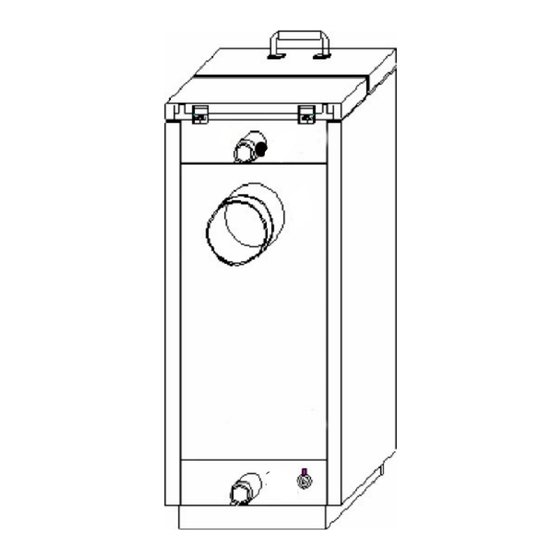
Page 4: Description Of Boiler & Manufacturers Plate
SECTION 2 Description of Boiler. 1 Supply to radiators, hot water tank etc. 2 Flue pipe/chimney connection. 3 Return from the radiators, hot water tank etc 4 Thermostat pocket . 5 Emptying and filling of water to the system. Manufacturers plate and serial number. Burner/ boiler type. -
Page 5: Dimensions Page 3
Dimensions of burner and wiring diagram. Page 4... -
Page 6: Fitting The Burner Into The Boiler
Section 3 Assembly. Fitting the burner unit. seal with fire rope or heat resistant gasket sealer to the boiler via the square hole located on side of boiler (left or right depending on requirement). mount the burner unit into flange and secure locking bolts Fitting the feed screw. -
Page 7: Feed Screw And Pellet Silo Assembly Page 5
Pellet silo assembly. The pellet silo….. As the pellets that you put into the silo contain dust, you should empty the silo completely from time to time. The more dust that is in the silo, the less pellets the feed screw will release and the boiler will become unadjusted, leading to inefficiency and possible breakdown. -
Page 8: Boiler Connection
Section 4 Installation. Power supply and connection. 230 volts 50Hz 10 Amp 60 Watts Control is supplied via a priming circuit breaker,(high limit safety cutout stat) which is mounted on the rear of the boiler (item 4, page 3). The temperature sensor is mounted in the same immersion pocket as the priming circuit breaker or a suitable place where the boiler temperature can be measured. -
Page 9: First Time Start Up
Section 5 Starting the unit for the first time. 1. check all connections on burner, boiler, feed screw, flue, chimney and power supply. 2. ensure that there are pellets at the inlet of the feed screw in the pellet silo. activate the forced feed operation by pressing the UP button on the... -
Page 10: Main Menu On Controller
Main menu on controller. In order to adjust the burner press the SET button on the controller and you will gain access to the main menu use There are four adjustment options in this main menu. 1. Boiler temperature: *factory settings 60 degrees* press the UP or DOWN buttons to reach the required water temperature. -
Page 11: Secondary Menu On Controller
Secondary menu on controller. To gain access to the secondary menu press and hold the SET button for 6 seconds. A1..The amount of fuel for stoking up at start Standard 32 sec. A2..Ignition Time Standard 10 min. A3..The effect of the electric ignition Standard 70 %. -
Page 12: Section 6
Section 6 Cleaning the burner. Switch off the control system by pressing the DOWN button for 5 seconds. Wait for approximately 5 minutes to allow the burner to cool down. When it has cooled down completely it is ready for cleaning. Take the connector off the burner, remove the shield and down pipe, and unscrew the burner unit off the boiler. -
Page 13: Troubleshooting
Trouble shooting. PROBLEM CAUSE SOLUTION Clean the burner cinders/ash in the burner head Clean the boiler, flue pipe and chimney ash in the boiler, flue pipe and Correct or remove the exhaust deflector plate chimney in the boiler flue deflector incorrectly mounted ALARM, WARM DOWNPIPE, Insulate and raise the chimney lack of draught in the chimney... -
Page 14: Installation Examples
Installation Design Examples 1: Forward movement. 2: Return. 3: Flue connection. 4: Over-temperature safeguard with sensors. 5: Pump. 6: Safeguards set 2.5 bars. 7: Pressure expansion. 8: Return valve with remote sensors/ Tap. 9: Thermometer. 10:Return valve. 11:Taps. 12:Hot water containers. 13:Feed. -
Page 15: Health And Safety
Page 13 Health and Safety. Pellet storage and supply Pellet stores/bins installed inside buildings must be built with one hour fire containment. In case of an accident If you find a person ill or unconscious near any fuel burning appliance, be careful in case you also become a casualty. -
Page 16: Quick Start Guide
Page 14... - Page 17 Quick Start NBE Pellets Systems adjust according to weight The UP key is held in when connecting power the DOWN key stops feed screw Run pellets in a bucket for 15 min Amount 360 sec. Pellets.(6 min) Read the result on the back side Put in the numbers in menu 2 –...
- Page 19 Quick Start 16kw NBE Pellets Systems Estimating Table.
- Page 20 Quick Start NBE Pellets Systems Estimating Table.
- Page 22 Quick Start NBE Pellets Systems Estimating Table.
Need help?
Do you have a question about the Scotte 16kw and is the answer not in the manual?
Questions and answers