
Subscribe to Our Youtube Channel
Related Manuals for Varifan VSD-1MC-20

Summary of Contents for Varifan VSD-1MC-20
- Page 1 VSD-1MC-20(40) MANUAL 0-10V / 4-20mA Variable Speed Module with Manual Override Varifan ® MANUAL AUTO MANUAL SPEED Installation / User’s Guide...
- Page 2 VSD-1MC-20(40) This guide will inform the electrician on proper wiring and installation procedures and, will also inform the user on how to use the VSD-1MC-20(40) module. The manufacturer recommends that the following installation instructions be followed to as closely as possible, and that all work be performed by a certified electrician.
-
Page 3: General Installation Guidelines
VSD-1MC-20(40) General installation guidelines It is recommended to install the unit in a hallway to limit the VSD-1MC-20(40) exposure to noxious gases. In order to avoid condensation problems inside the VSD-1MC-20(40), it is recommended to install the module on an inside wall. If it is not possible, use spacers to have an air gap between the wall and the module. - Page 4 VSD-1MC-20(40) Figure 1: Wiring Diagram SOLDER OR USE PROVIDED WIRE CONNECTOR 230V 0-10 Volts or 4-20 mA INPUT SIGNAL LINE VOLTAGE 115/230 WARNING! To avoid electric shock, disconnect power source prior to installation or troubleshooting. Make sure that the Voltage Selector switch is set to the correct voltage before powering up the module.
- Page 5 VSD-1MC-20(40) Using the VSD-1MC-20(40) With the VSD-1MC-20(40) you can control a variable fan according to a 0-10 Volts or 4-20 mA input signal. Refer to figure 2 for the location of the different switches, jumpers and selectors of the different module.
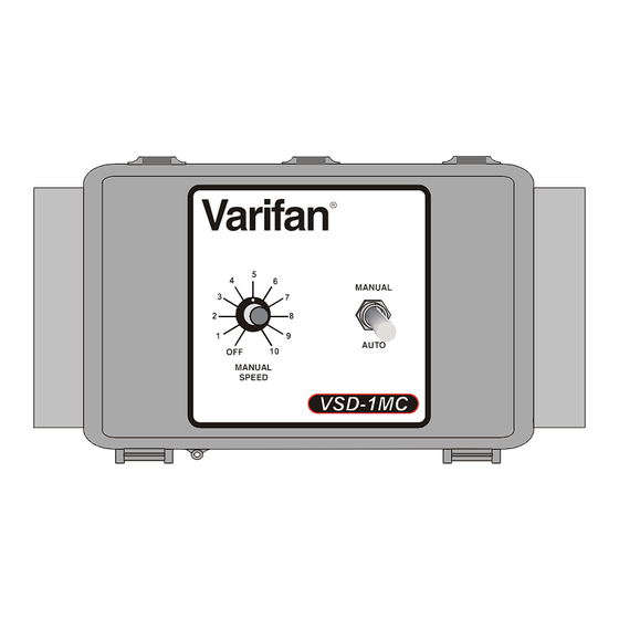
- Page 6 VSD-1MC-20(40) Figure 3: VSD-1MC-20(40) Faceplate Varifan ® MANUAL AUTO MANUAL SPEED 1. Manual Speed Selector This selector is used to set the speed at which the variable output will run when the AUTO/MANUAL Switch is set to MANUAL. The variable output will shutoff is the Manual Speed Selector is turned completely counter clockwise (OFF).
- Page 7 VSD-1MC-20(40) The VSD-1MC-20(40) module uses a 0-10 Volts or a 4-20 mA signal to make an output modulates. User can adjust the fan minimum speed with the potentiometer located inside the module box on the electronic board (refer to figure 2). That Minimum Speed Potentiometer is used to adjust the speed when the master control input signal is at its lowest value.
-
Page 8: Fan Speed
VSD-1MC-20(40) Figure 4: Logic Diagrams (Auto Mode) AUTO MODE Switch 1 = OFF (0-10 Volts or 0-20 mA) Switch 2 = OFF (No shutoff at 5%) Fan Speed 100% Minimum Speed 10 Volts Input or 20 mA AUTO MODE Switch 1 = ON (2-10 Volts or 4-20 mA) - Page 9 VSD-1MC-20(40) AUTO MODE Switch 1 = OFF (0-10 Volts or 0-20 mA) Switch 2 = ON (Shutoff at 5%) Fan Speed 100% Minimum Speed 10 Volts Input or 20 mA 0.7 Volts 0.5 Volts or 1.4 mA or 1 mA...
-
Page 10: Manual Mode
VSD-1MC-20(40) Figure 5: Logic Diagram (Manual Mode) MANUAL MODE Switch 1 and Switch 2 are not used in manual mode Fan Speed 100% Minimum Speed Faceplate (100%) Potentiometer (7%) (5%) Page 10... -
Page 11: Specifications
Input Range 0-10 Volts or 0-20 mA Maximum wire length 500 feet (150 m) Recommended wires 2 conductor wire, AWG #22 VARIABLE OUTPUT (VSD-1MC-20) Recommended maximum current 20 A, 250 VAC Minimum load 300 mA @ 230 VAC VARIABLE OUTPUT (VSD-1MC-40) -
Page 12: Limited Warranty
VSD-1MC-20(40) Limited Warranty The manufactured equipment and supplied components have gone through rigorous inspection to assure optimal quality of product and reliability. Individual controls are factory tested under load, however the possibility of equipment failure and/or malfunction may still exist. - Page 13 VSD-1MC-20(40) VER : 1.0 November 17, 2011...
Need help?
Do you have a question about the VSD-1MC-20 and is the answer not in the manual?
Questions and answers