
Summary of Contents for Conductix-Wampfler BEF150
- Page 1 Installation Manual Spring Cable Reel BEF150 – BEF500 MAL6100-0001a-EN www.conductix.com translated document Page 1 of 54...
-
Page 2: Table Of Contents
Installation Manual Spring Cable Reel BEF150 – BEF500 Contents General Notes ............................5 About this document ........................... 5 Limitation of liability ............................ 5 Copyright ..............................5 Spare parts ..............................6 Warranty and guarantee ..........................6 Customer service............................6 Safety Rules ............................7 Requirements on the personnel ......................... - Page 3 Installation Manual Spring Cable Reel BEF150 – BEF500 6.1.1 Safety instructions for transport ........................ 16 6.1.2 Transport inspection ..........................16 Packing ..............................17 Storage of packed parts ........................... 17 Commissioning ............................ 18 Mechanical attachment ..........................18 Electrical installation ..........................23 7.2.1 Connecting the feed cable ........................
- Page 4 Installation Manual Spring Cable Reel BEF150 – BEF500 12 Additional Documents ......................... 52 13 Indices ..............................53 13.1 Figures ..............................53 13.2 Keywords ..............................54 MAL6100-0001a-EN www.conductix.com translated document Page 4 of 54...
-
Page 5: General Notes
Installation Manual Spring Cable Reel BEF150 – BEF500 1 General Notes 1.1 About this document This document makes it possible for you to work safely and efficiently with a spring cable reel. This document is a part of the spring cable reel, and must be kept accessible to personnel at all times in its immediate vicinity. -
Page 6: Spare Parts
Germany www.conductix.com Replacement parts list: Separate document delivered with the order. If necessary, request from Conductix-Wampfler. Please specify the order number in your request. 1.5 Warranty and guarantee The terms of warranty and guarantee can be found in the General Terms of Business of the manufacturer (see www.conductix.de). -
Page 7: Safety Rules
Installation Manual Spring Cable Reel BEF150 – BEF500 2 Safety Rules Safety and hazard information is identified in this manual by the use symbols. Signal words are used to indicate the degree of hazard in these safety instructions. Always observe safety and hazard information and work carefully to avoid accidents, bodily harm or property damage! ... -
Page 8: Requirements On The Personnel
Installation Manual Spring Cable Reel BEF150 – BEF500 2.1 Requirements on the personnel 2.1.1 Qualifications Injury due to insufficient qualifications! Improper use can result in serious injury to person and property. → All activities may only be performed by qualified personnel. -
Page 9: Instruction
Installation Manual Spring Cable Reel BEF150 – BEF500 2.1.3 Instruction Before commissioning the equipment, personnel must be instructed by the operator. For better transparency, the performance of this instruction must be logged. Example of instruction log: Date Name: Type of instruction... -
Page 10: Intended Use
Installation Manual Spring Cable Reel BEF150 – BEF500 2.3 Intended use The spring cable reel is used for the transmission of power and data to mobile consumers with automatic winding using a coil spring. Unwinding is not carried out manually, but rather by the mobile consumer. -
Page 11: Terminology
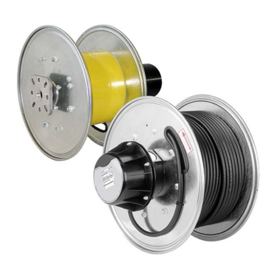
Installation Manual Spring Cable Reel BEF150 – BEF500 3 Terminology Fig. 1 Main assemblies of the spring cable reel Item Description End flange, both sides Slip ring body, housing with type plate Reel-capable cable (optional) Coil spring with protective guard... -
Page 12: Technical Specifications
Installation Manual Spring Cable Reel BEF150 – BEF500 4 Technical Specifications 4.1 Type plate The type plate is located on the top part of the slip ring body housing (see Fig. 2). The technical specifications can be read off the type plate (depending on the model and variant). -
Page 13: Operating Conditions
Installation Manual Spring Cable Reel BEF150 – BEF500 4.3 Operating conditions Requirements for the working environment: Designation Value Notes Winding behaviour 0.3 m/s Max. acceleration Temperature range -20 to 40 °C Operation in air Maritime climate possible for short periods, mild chemical atmosphere, not in radioactive environment Other values may be possible upon request. -
Page 14: Functional Description
Installation Manual Spring Cable Reel BEF150 – BEF500 5 Functional Description 5.1 Function The spring cable reel is designed for the automatic coiling cables for mobile consumers. The cable is wound using pretensioned coil springs that are installed inside the body of the reel. -
Page 15: Danger Zone
Installation Manual Spring Cable Reel BEF150 – BEF500 5.3 Danger zone When using spring cable reels, there are two main danger zones to take into consideration: Rotating reel During operation, the reel cable is unrolled and/or rolled back in under spring tension. The reel body turns during these actions. -
Page 16: Transport And Storage
Installation Manual Spring Cable Reel BEF150 – BEF500 6 Transport and storage 6.1 Shipment 6.1.1 Safety instructions for transport Danger of death due to hanging loads! Falling parts or those swinging out of control can lead to severe injury or even death. -
Page 17: Packing
Installation Manual Spring Cable Reel BEF150 – BEF500 6.2 Packing The individual packaged parts must be packed according to the transport conditions to be expected. Only environmentally friendly materials have been used for packaging. The packaging must protect the individual components from transport damages, corrosion, and other damage until installation. -
Page 18: Commissioning
Installation Manual Spring Cable Reel BEF150 – BEF500 7 Commissioning Installation → During electrical installation of the reel, note whether it was delivered with or without the wound cable. CAUTION! Commissioning may only be carried out by an electrician. CAUTION! 7.1 Mechanical attachment... - Page 19 Installation Manual Spring Cable Reel BEF150 – BEF500 Fig. 4 Drilling template BEF150/61-F001-0039 MAL6100-0001a-EN www.conductix.com translated document Page 19 of 54...
- Page 20 Installation Manual Spring Cable Reel BEF150 – BEF500 Fig. 5 Drilling template BEF185 – 325/61-F001-0055 MAL6100-0001a-EN www.conductix.com translated document Page 20 of 54...
- Page 21 Installation Manual Spring Cable Reel BEF150 – BEF500 Fig. 6 Drilling template BEF400 – 500/61-F001-0056 MAL6100-0001a-EN www.conductix.com translated document Page 21 of 54...
- Page 22 Installation Manual Spring Cable Reel BEF150 – BEF500 During installation, please note: → The axis of the spring cable reel must always be positioned horizontally. → The screw attachment surface must be flat. Axis horizontal Screw attachment surface flat Fig. 7 Fastening flange and reel axis Reel attachment The threaded pin for attaching the flange (detail A, Fig.
-
Page 23: Electrical Installation
Installation Manual Spring Cable Reel BEF150 – BEF500 7.2 Electrical installation Connecting the reel cable Attach tension relief! → To avoid damage to the cables, always provide sufficient tension relief CAUTION! Note before turning on! → Before the device or system is started, test the insulation resistance according to locally... - Page 24 Installation Manual Spring Cable Reel BEF150 – BEF500 Cable connections, Cable connections, earth, feed reel cable Fig. 8 Cable connections on the slip ring body Connecting the reel cable: → Remove slip ring body hub. → Guide the mobile cable (= reel cable) through the slot in the outer round plate and into the collar in the lower part of the hub in the slip ring body.
- Page 25 Installation Manual Spring Cable Reel BEF150 – BEF500 The current collector variants: Fig. 9 Type 45 current collector connection Fig. 10 Types 13, 15 current collector connection MAL6100-0001a-EN www.conductix.com translated document Page 25 of 54...
- Page 26 Installation Manual Spring Cable Reel BEF150 – BEF500 Fig. 11 Types 16, 19 current collector connection Fig. 12 Type 18 current collector connection MAL6100-0001a-EN www.conductix.com translated document Page 26 of 54...
- Page 27 Installation Manual Spring Cable Reel BEF150 – BEF500 Fig. 13 Types 18 current collector connection with blade receptacle → Wind the reel cable by hand without twisting it, and tie the cable end onto the reel. → Pretension the reel with n turns (see section 4.1) in the take-off direction and secure against rewinding.
-
Page 28: Connecting The Feed Cable
Installation Manual Spring Cable Reel BEF150 – BEF500 7.2.1 Connecting the feed cable Danger of death by electrocution! Contact with components carrying electrical power can lead to death or severe injury by electrocution. Danger of injury due to shock reactions, falling, or being thrown away due to WARNING! electrical shock. - Page 29 Installation Manual Spring Cable Reel BEF150 – BEF500 Fig. 14 Type 13, connection plate with terminals Fig. 15 Type 18, connection plate with terminals Fig. 16 Type 45, terminal board with terminals MAL6100-0001a-EN www.conductix.com translated document Page 29 of 54...
-
Page 30: Pretensioning
Installation Manual Spring Cable Reel BEF150 – BEF500 7.3 Pretensioning 7.3.1 Adjustment Connecting the reel Danger of injury from pretensioned drive springs! If the spring tension is released suddenly, the reel can turn at high speed in an uncontrolled manner. This can cause impacts, crushing, shearing and other severe injuries. -
Page 31: Operation
Installation Manual Spring Cable Reel BEF150 – BEF500 8 Operation 8.1 Safety Danger of injury due to improper operation! Improper operation can result in serious injury to person and property. → Carry out all operating steps according to the specifications of these instructions. - Page 32 Installation Manual Spring Cable Reel BEF150 – BEF500 The cable can only be properly wound if the maximum permissible angle is observed! Fig. 17 Optimum winding behaviour MAL6100-0001a-EN www.conductix.com translated document Page 32 of 54...
- Page 33 Installation Manual Spring Cable Reel BEF150 – BEF500 Correct arrangement of the cable reel and the cable fixed The maximum permissible angle still point. applies when guide rollers are used. If necessary, increase the distance from the guide rollers to the cable reel.
-
Page 34: Service
Installation Manual Spring Cable Reel BEF150 – BEF500 9 Service 9.1 Safety Danger of death by electrocution! Contact with components carrying electrical power can lead to death or severe injury by electrocution. Danger of injury due to shock reactions, falling, or being thrown away due to WARNING! electrical shock. - Page 35 → Check all wires for firm connections and damage to insulation. Replace current collector: Conductix-Wampfler uses different types of current collectors! → Disconnect all cables from power and secure against being turned back on. → Unscrew and remove the housing of the slip ring body.
- Page 36 Installation Manual Spring Cable Reel BEF150 – BEF500 Fig. 21 Type 16, current collector with slip ring Fig. 22 Type 18 current collector, assembly/disassembly and slip ring Fig. 23 Type 19, current collector with slip ring MAL6100-0001a-EN www.conductix.com translated document...
-
Page 37: Replacing Springs
Installation Manual Spring Cable Reel BEF150 – BEF500 Fig. 24 Type 45/1 + 45/3: Current collector with slip ring and wire Fig. 25 Type 45/2, current collector with slip ring and wire Cables: → Check that cables are installed without twisting. If necessary, loosen the cable and install it so that it is not twisted. -
Page 38: Prerequisites
Installation Manual Spring Cable Reel BEF150 – BEF500 Danger of fatal injury from pretensioned drive springs! The drive springs are installed in protective metal housings for protection from injury. If the protective housings are opened, then the drive springs (coils of spring steel) can be released DANGER! from the protective housing in an uncontrolled manner. - Page 39 Installation Manual Spring Cable Reel BEF150 – BEF500 "Left" take-off: BEF185 – BEF500 BEF150 Fig. 26 Changing springs, series connection with left take-off BEF185 – BEF500 → On the flange side, loosen the hex nuts [10] of the protective housing bolts and the hex nuts [5] of the connection between the end flange and the reel body.
- Page 40 Installation Manual Spring Cable Reel BEF150 – BEF500 "Right" take-off: BEF185 – BEF500 BEF150 Fig. 27 Changing springs, series connection with right take-off BEF185 – BEF500 → On the flange side, loosen the hex screws [5] of the connection between the end flange and the reel body.
- Page 41 Installation Manual Spring Cable Reel BEF150 – BEF500 9.3.2.2 Installation Even the unbroken springs should be replaced, since they can soon be expected to suffer from fatigue. → Before reassembly, coat the spring nuts and their holes generously with acid-free, elastic grease.
-
Page 42: Parallel Connection
Installation Manual Spring Cable Reel BEF150 – BEF500 9.3.3 Parallel connection Spring designation, e.g.: 2DH (T) or 2UA (T) BEF185 – BEF500 BEF150 Fig. 28 Changing springs, parallel connection 9.3.3.1 Dismantling → Loosen the threaded pin [1] of the fastening flange. - Page 43 Installation Manual Spring Cable Reel BEF150 – BEF500 9.3.3.2 Installation Even the unbroken springs should be replaced, since they can soon be expected to suffer from fatigue. → Before reassembly, coat the spring nuts and their holes generously with acid-free, elastic grease.
-
Page 44: Changing The Direction Of Rotation
Installation Manual Spring Cable Reel BEF150 – BEF500 9.4 Changing the direction of rotation 9.4.1 Series connection Spring designation, e.g.: 2DH (T) H or 2UA (T)H [H for series connection] BEF185 – BEF500 Fig. 29 BEF185 – BEF500 change of rotation direction, series connection with left/right take-off →... - Page 45 Installation Manual Spring Cable Reel BEF150 – BEF500 → Secure the threaded pin [1] against loosening. → Seal the cuts on the reel with silicone. → Connect the reel (see Chapter 7). Danger of death by electrocution! → Earth the device on the earthing connection (PE) of the slip ring body!
- Page 46 Installation Manual Spring Cable Reel BEF150 – BEF500 → Turn the final single spring nut [9] by 180°C and fasten it to the axis. Carefully pull out the axis until the fastening bolts are accessible. → Insert the end flange with its bearing flange [6] onto the axis (with the spacer as stop) and use the cylinder screws [5] to fasten it to the reel body.
-
Page 47: Parallel Connection
Installation Manual Spring Cable Reel BEF150 – BEF500 9.4.2 Parallel connection Spring designation, e.g.: 2D H (T) or 2UA (T) BEF185 – BEF500 Fig. 31 BEF185 – FEB500 Change of rotation direction, parallel connection → Section 9.3 describes the steps needed for preparation. - Page 48 BEF150 – BEF500 BEF150 Fig. 32 BEF150 Change of rotation direction, parallel connection → Section 9.3 describes the steps needed for preparation. → Loosen the threaded pin [1] of the fastening flange, then pull off the flange [2], V-ring [3] and spacer [4].
-
Page 49: Troubleshooting
Installation Manual Spring Cable Reel BEF150 – BEF500 10 Troubleshooting Danger of injury due to improper troubleshooting! Improper troubleshooting can result in serious injury to person and property. → Contact the manufacturer in case of malfunction WARNING! → Have troubleshooting carried out only by personnel from or authorized by the manufacturer... -
Page 50: Dismantling And Disposal
Installation Manual Spring Cable Reel BEF150 – BEF500 11 Dismantling and disposal 11.1 Safety Danger of injury due to improper disassembly! Stored energy, sharp components, points, and edges on and in the device or the tools needed can cause injury. -
Page 51: Disposal
Installation Manual Spring Cable Reel BEF150 – BEF500 Danger of death due to hanging loads! Falling parts or those swinging out of control can lead to severe injury or even death. → Never step under hanging loads WARNING! → Only use the attachment points provided; do not fasten lifting accessories to projecting machine parts or components built onto eyes. -
Page 52: Additional Documents
Installation Manual Spring Cable Reel BEF150 – BEF500 12 Additional Documents Additional Documents: Declaration of incorporation Dimensional drawings Spare parts list Applicable documents: BAL6100-0001-Drive springs TI5100-0007-Slip ring body wear limits MAL6100-0001a-EN www.conductix.com translated document Page 52 of 54... -
Page 53: Indices
Fig. 30 BEF185 Change of rotation direction, series connection with left/right take-off ............45 Fig. 31 BEF185 – FEB500 Change of rotation direction, parallel connection ................ 47 Fig. 32 BEF150 Change of rotation direction, parallel connection ..................48 MAL6100-0001a-EN www.conductix.com... -
Page 54: Keywords
Installation Manual Spring Cable Reel BEF150 – BEF500 13.2 Keywords Changing the direction of rotation ........44 Protection class ..............11 Construction ............... 14 Protective equipment ............9 Copyright ................5 Protective guard ..............11 Customer service ..............6 Protective measures ............10 Safety instructions ..............
Need help?
Do you have a question about the BEF150 and is the answer not in the manual?
Questions and answers