Table of Contents
Advertisement
Advertisement
Table of Contents

Subscribe to Our Youtube Channel
Summary of Contents for RMF Systems CMS 2
- Page 1 User Manual CMS2...
- Page 2 As a policy of continual improvement, RMF reserves the right to alter the specification without prior notice. 201.028 REV 1 Date of Issue: 18 June 2018...
-
Page 3: Table Of Contents
Table of Contents 1 General Warnings and Information for the End User ....................5 1.1 General Safety Warnings ............................ 5 1.3 Operator Position and Dangerous Areas ......................6 1.4 Dangers and Hazards that cannot be eliminated ....................6 1.5 Personal Protective Equipment .......................... 7 2 Transportation and Storage ............................ - Page 4 6.2.3 CMS removal and Product Maintenance ....................30 6.3 CMS Control ..............................31 6.3.1 Computer Connection ..........................31 6.3.2 PC Software Operation ..........................32 6.3.3 Settings ..............................33 6.4 Standard Communication Protocols ......................... 42 6.4.1 Modbus ..............................42 6.4.2 CAN-bus ..............................46 6.4.3 Analogue 4-20mA Modes ..........................
- Page 5 11.5 NAS1638 Cleanliness Code System (now defunct, replaced by SAE AS4059E Table 1) ......... 76 11.6 SAE AS4059 REV E Cleanliness Classification for Hydraulic fluids ..............76 11.7 Recommendations ............................77 11.8 Hydraulic System Target Cleanliness Levels ....................78 11.9 New ISO Medium Test Dust and its effect on ISO Contamination Control Standards ........79 11.10 Clean Working Practices ..........................
-
Page 6: General Warnings And Information For The End User
1 General Warnings and Information for the End User 1.1 General Safety Warnings Do not operate, maintain or carry out any procedure before reading this manual. Any individual operating the unit shall wear the following Personal Protective Equipment: Protective eyewear Safety shoes Gloves Overalls (or other suitable protective clothing) -
Page 7: Operator Position And Dangerous Areas
MACHINE SETTER This is any individual whose task is to set up the machine for its operation. The machine setter is aware of the measures taken to eliminate all sources of injury risks in the workplace and takes into account the operational constraints. The machine setter takes all the appropriate precautions in order to operate in utmost safety conditions. -
Page 8: Personal Protective Equipment
1.5 Personal Protective Equipment When operating the unit, personnel must be wearing safety shoes, gloves and goggles. In general, the PPEs to be used according to the activities on the machinery are listed in the following table: Activity PPEs Ordinary operation Shoes, gloves, goggles, overall Planned maintenance Shoes, gloves, goggles, overall... -
Page 9: Transportation And Storage
2 Transportation and Storage 2.1 Transportation and Handling Conditions The unit is shipped in a cardboard box, encased in polyurethane foam. The packed weight of the CMS and accessories is 2.5kg. 2.2 Storage The unit should be stored in a suitable location away from the production area when not in use. The unit should be stored with the caps provided on the ports. -
Page 10: Warranty, Limitations And Disclaimers
Any product returned for warranty repair must be accompanied by a full fault report specifying the symptoms and the conditions under which the fault occurs. Should RMF Systems incur additional cost as a result of a failure to complete the appropriate paperwork, an administrative charge may be levied. - Page 11 RMF Systems obligations under this warranty. Should the customer’s product be damaged in transit following a repair at RMF Systems site, a full photographic record of the damage must be obtained (packaging and the product) to support any claim for recompense.
-
Page 12: Product Presentation
4 Product Presentation The CMS measures and quantifies the numbers of solid contaminants in Hydraulic, Lubrication and Transmission applications. The CMS-M is designed to be an accurate instrument for permanently installed applications utilising mineral oil as the operating fluid. Other fluid media versions are available for offshore [N] and aerospace phosphate ester [S] applications. -
Page 13: Data Logger
4.2.2 Data Logger The CMS includes a built-in data logger, which adds the facility to log and timestamp test results locally within an internal memory, even when not connected to a computer. − Test logging is determined by the log settings (see section 6.3.3). −... -
Page 14: Technical Specification
5 Technical Specification 5.1 Performance Technology LED Based Light Extinction Automatic Optical Contamination Monitor Particle Sizing >4, 6, 14, 21, 25, 38, 50, 70μm Analysis range ISO 4406: Code 0 to 25 NAS 1638 Class 00 to 12 AS4059 Rev E Table 1 & 2 Sizes A-F: 000 Please Note: (Lower Limits are Test Time dependent) If system cleanliness is expected to be above 22/21/18 or approx. - Page 15 G3 ¼” BSPP Female Port G4 7/16 UNF Female Port Seal Material M/N Version – Viton (contact RMF Systems for any fluids that are incompatible with Viton seals S Version - Perfluoroelastomer As a policy of continual improvement, RMF reserves the right to alter the specification without prior notice.
-
Page 16: Fluid Characteristics
5.4 Fluid Characteristics Fluid compatibility M version - mineral oils, synthetic fluids and diesels N version – water based/ subsea fluids & M version fluids S version – Aerospace phosphate esters, Skydrols® and N & M version fluids. Viscosity ≤ 1000 cSt Fluid temperature -25°C to +80°C Operating Flow Rate... -
Page 17: Environment
Maximum Pressure 420barg static (For high frequency pressure pulse applications contact RMF Systems) Differential Pressure Typically 0.5bar 5.5 Environment Ambient working temperature -25°C to 80°C non K version / -25°C to 55°C K version IP Rating IP66 IK Rating IK04 5.6 Wetted Parts List... -
Page 18: Product Installation And General Operation
6 Product Installation and General Operation 6.1 Installation Each CMS supplied consists of the following: − − Calibration certificate − USB Stick which includes: Product User Guides, RMF-View software, accessory product drivers and product brochures − Pre-wired 3m cable − Quick Start Guides Optional Equipment: −... -
Page 19: Electrical Interface
6.1.2 Electrical Interface RMF Systems’ separate CMS-USBi product is available for those wishing to have a simple plug and play solution providing connection of the CMS to a computer. This section is for those wishing to do their own wiring to the product. - Page 20 Figure 6.1 Connector Orientation Figure 6.2 Machine Connector External Wiring Example 6.1.2.2 DC Power DC power is connected to pins 7 and 8 of either circular connector (Red and Blue if using the pre-wired cable). All the other signals are optional. Item Minimum Maximum...
- Page 21 Adapters are available to interface to other industrial control busses. The standard RMF-View software from RMF Systems itself uses Modbus to communicate with the CMS, but it is also possible for customers to implement their own controllers (section Modbus).
- Page 22 Figure 6.4 Multi-Drop Network Example Figure 6.4 shows how to connect two or more CMS devices to a multi-drop RS485 network. Any termination resistors should be fitted to the network cable ends only. Spurs off the main RS485 bus should be kept as short as possible, e.g.
- Page 23 Figure 6.6 Switched I/O Signals In order to reduce wiring the input and outputs all connect together on one side (see Figure 6.6). However they are optically isolated from the rest of the system so can be used to switch unrelated signals. 6.1.2.5 Start Signal The "start signal’’...
- Page 24 − This is not the same thing as the "start signal delimited test" option ("start signal defines test duration" in user settings when enabled). This is for using the start signal to control the duration of each *single* test, only. Other ways to test are: −...
-
Page 25: Hydraulic Connection
Figure 6.7 4-20mA Example 6.1.3 Hydraulic Connection 1 High or Low Pressure Parallel Connection Figure 6.8 CMS working pressure generated by hydraulic component As a policy of continual improvement, RMF reserves the right to alter the specification without prior notice. 201.028 REV 1 Date of Issue: 18 June 2018... - Page 26 2 Low Pressure, Off-Line Operation Figure 6.9 CMS working pressure generated by hydraulic component 3 Very Low Flow Systems Figure 6.10 Entire system flow rate is within the range of the CMS 6.1.3.1 Flow Rate For the majority of systems, a differential pressure of a few Bar will generate an in-range flow for a CMS connected using two 1.5 meter lengths of microbore pressure hose.
- Page 27 − Use the figure 6.11 to look up the pressure drop, across the CMS ports, at this flow rate and viscosity. E.g. at 30cSt and 200ml/minute, this is 0.4 Bar. The maximum and minimum allowed differential pressures can also be determined using the 400ml/min and 20ml/min lines, respectively. −...
-
Page 28: General Operation
Figure 6.11 Differential Pressure vs Fluid Viscosity, for various flow rates 6.1.3.2 Manual Flow Control Another possibility is to fit a simple manual flow control (flow restrictor) to the outlet of the CMS. − This should only be done where the available pressure is less than twice the maximum value calculated. This is because the small orifice size needed to control the flow from a pressure larger than this has a risk of blockage. -
Page 29: Front Panel Operation
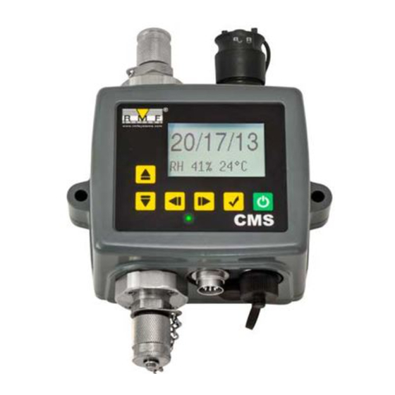
All CMS versions have a multi-colour indicator on the front panel, which is used to indicate the status or alarm state. CMS-K versions also have a screen that changes colour. The alarm thresholds can be set from RMF-View via the serial interface. Figure 6.13 Front panel of K version (left) and Non-K version (right) CMS 2 Colour Shows Green Indicates that the test result has passed, i.e. - Page 30 6.2.2.2 Front Panel Operation 6.2.2.2.1 Result Display CMS-K models have a 6 button keypad and a small graphical LCD. This allows the display of the test result (current cleanliness level, with water content and temperature if applicable). The graphical format allows a full display of all codes of the standards supported. The unit powers up in "Display Mode’’.
-
Page 31: Cms Removal And Product Maintenance
Figure 6.14 History Screen The progress of a test is denoted by the horizontal line; it grows from left to right as the test progresses. When it reaches the right hand side a new result is generated. 6.2.2.2.2 Diagnostics Display Press ◄... -
Page 32: Cms Control
− If this doesn’t solve the issue then send to RMF Systems for investigation. 6.3 CMS Control The CMS can be controlled using the remote control facility included in the RMF-View software package, installed on a computer. Alternatively customers can use their own computer software. -
Page 33: Pc Software Operation
Figure 6.17 Figure 6.18 The first time that this is done, the correct communications port (COM port) on the computer has to be selected, as detailed below. − The program scans the computer for available ports, and puts them in a list to choose from - this list is in the box above the Connect button. -
Page 34: Settings
Figure 6.19 To perform a test, first optionally edit the Test Reference and press Apply to register the new value. This is a descriptive label which can be used to identify or group the test later (along with the test number and test time/date). - Page 35 Figure 6.20 NOTE: The CMS has been designed to be a very flexible product, so has a wide range of settings and operating modes. However the shipped defaults are suitable for most applications and many users can skip this section. Actual operation is straightforward even when advanced settings are used during initial configuration.
- Page 36 Figure 6.21 NOTE: if the CMS is power cycled at any point then the test numbering sequence automatically resets and begins again. 6.3.3.3 Test Duration The length of the test is controlled by the Test Duration, see figure 6.21 for location. The factory set value of 2 minutes is suitable for most applications, but the user is free to set a different value.
- Page 37 − The CMS needs particles to pass through the flow cell to calculate flow, the dirtier the system is, the more statistically accurate the flow output becomes. − Conversely, when placed on a very clean system the unit can have difficulty in working out the flow due to the very low number of particles passing through the flow cell.
- Page 38 If continuous logging is used, then the Log Interval can be set to control the proportion of tests that are actually logged. For example the CMS could be set to test every 10 minutes, but only log a result hourly. The log interval, test interval and test duration are distinct parameters that work together to control the test and data logging.
- Page 39 Figure 6.25 Selecting a machine interface fixes the output for the machine connector, for example selecting CANbus means that you can no longer use the machine connector to communicate in Modbus (the default). If you wish to change back or to a version of 4-20mA then you have to connect to the CMS via the Remote Connector. See section 6.4 for information on how to communicate with the CMS in the different protocols.
- Page 40 Figure 6.24 ISO4406:1999 Alarm Levels ISO4406:1999 represents cleanliness using codes for the number of particles greater than 4, 6 and 14µm. These codes can be used as limits for the alarms by selecting the ISO4406:1999 test Format and then entering values as required.
- Page 41 AS4059E Table 2 uses letters instead of numbers to indicate the particle size range, so the settings are labelled appropriately. The standard specifies ways to represent a cleanliness level using only a subset of the available particle sizes, for example B-F. The user can achieve this by only entering settings for the sizes desired, leaving the others empty.
- Page 42 Alarm Mode 0: Warning-Alarm Output 1 Output 2 Turns on When >Lower >Upper Intended Function Warning Alarm This allows the CMS to switch external warning lights or alarms. Output 1 is the "Warning’’ output, switching on if any of the Lower limits are exceeded. Output 2 is the "Alarm’’ output, behaving similarly for the upper limit. Alarm Mode 1: Clean-Dirty Output 1 Output 2...
-
Page 43: Standard Communication Protocols
Alarm Mode 5: Tested Not-Clean Output 1 Output 2 Turns on When Test Complete >Lower Intended Function Test Complete Signal “Not Clean” Signal This is used when controlling tests from a PLC using switched outputs. The PLC gives a start signal, then monitors the "Test Complete’’... - Page 44 6.4.1.1 Set Up Protocol Type RTU (not ASCII) Data Bits Stop Bits Parity Required, Even or none Baud Auto-sensing 1200-115200 Signaling RS485 Node Address 4 (or user set) Figure 6.29 Settings 6.4.1.1.1 Communications Check You should be able to read the product ID code from register 0 (from Modbus node address 204). The product ID code is the value 54237 (decimal) or 0xD3DD (hexadecimal).
- Page 45 6.4.1.2 Result Codes The most recent measurements are presented as numeric codes (i.e. numbers) according to the selected TEST FORMAT. These codes can be read from registers 56-63, as per Table 6B. Register ISO 4406 Code AS4059E Table 2 NAS1638/ AS4059E Table 1/ ISO Class 11218 (Draft) Codes/ Classes ≥4µ...
- Page 46 6.4.1.2.4 AS4059E-2 AS4059E Table 2 also has some similarities to NAS1638. In terms of the representation in Modbus registers, the main differences are an extra 4-6μm(c) size range and the addition of an extra ``000’’ class. This is represented using the number -2. If the user program interprets this as a positive number it will appear as 65534 (0xFFFE hex). 6.4.1.2.5 Temperature and Water Content Measurements These are contained in the TEMPERATURE register 33 and the RH (relative humidity) register 34.
-
Page 47: Can-Bus
combination makes up a 32-bit integer. For example, the value of such a 32 bit unsigned integer stored in the two registers 40 and 41 may be calculated using the formula: ���������� = (65536 × (���������������� 40)) + (���������������� 41) The particle counts are stored in registers 40-55, as shown in Table 6D. - Page 48 J1939 and CanOpen are higher level protocols built on these basic standards. J1939 uses CAN2.0A, and CanOpen uses CAN2.0B. The CMS does not implement either of these protocols. Instead it defines a few CAN-bus messages to communicate data. However the message identifiers have been chosen so as to allow operation with both J1939 and CanOpen.
- Page 49 6.4.2.2 Configuration 6.4.2.2.1 Use PC Software for Configuration The free RMF-View software package is needed in order to initially configure the CMS. Once configured, the unit can be left connected to the CAN-bus network. The CMS was designed to be as flexible as possible. There are large number of options for setting operating modes, test result formats, alarm settings, downloading stored data etc.
-
Page 50: Analogue 4-20Ma Modes
6.4.2.2.3 CAN2.0A and CanOpen The 11 bit format is designed to be compatible with the CanOpen standard. It can also be used with any system that allows raw CAN-bus 2.0A identifiers to be received. In order to use 11 bit identifiers (CAN 2.0A) set a value below 0x7ff for the ``Base Address’’. For a CanOpen network, use a base address of 0x182 for example. - Page 51 PLC. The PLC would need to be programmed to read each parameter at the correct time. These modes are still under development; please contact RMF Systems for details. − We output a current <5mA (4.0mA) for 1 second to indicate start of "frame", this is denoted by <SYNC> in the following examples.
-
Page 52: Disposal
ISO4406 codes are encoded as: ���� = 6 + ������ / 2 ������ = 2 × (���� − 6) So 6mA = ISO 0, 20mA = ISO28 AS4059E2 Parameters are output in the sequence: <SYNC> <BASIC> <A> <B> <C> <D> <E> <F> <RH> <TEMP> <...> AS4059E2 contamination codes are encoded as: ����... -
Page 53: Troubleshooting / Faq
1. Optical - An optical fault could indicate LED failure or blockage of the optical path. Try flushing with Petroleum Ether, or return to RMF Systems. Low Flow - The CMS estimates the flow by measuring the transition time of the particles. The Low Flow warning indicates that the flow rate is below the minimum recommended level . -
Page 54: Test Status
The standard CMS is fitted with Viton seals, so Petroleum Ether or Iso Propyl Alcohol may be used for this purpose, in conjunction with the RMF Systems Bottle Sampling Unit. See flushing guidelines on supplied product USB. -
Page 55: Test Duration
7.3 Test Duration The set Test Duration is the amount of time for which particle counts are accumulated, before the test result is updated. The default of 120 seconds is likely to be suitable for most applications. However it is possible to set other values. -
Page 56: How To Order
8 How to Order 8.1 Common Features -All versions can be controlled by a PC, PLC or the CMS-RDU Remote Display Unit. -Time- stamped data-logging for around 4000 tests -An integral status LED to indicate fault conditions -RS485/CANBUS/4-20mA communications -Measurement in multiple international standard formats -All units include 3m pre-wired control cable and RMF-View test analysis software. -
Page 57: Related Products
9 Related Products 9.1 RDU 2.0 The optional CMSRDU2 is a separate accessory product allowing control of a CMS that is typically inaccessible via the keypad, display and USB download. The sensor itself is mounted remotely in another unit (normally a non-screened version). This allows the operator full control of the CMS. -
Page 58: Service And Recalibration
The CMS is recommended to be recalibrated every 12 months. Return to RMF Systems for recalibration. As a policy of continual improvement, RMF Systems reserves the right to alter the specification without prior notice. As a policy of continual improvement, RMF reserves the right to alter the specification without prior notice. -
Page 59: Reference
11 Reference 11.1 Further Modbus Information The CMS is a Modbus Slave. That is, it responds only to commands sent to it by the Modbus controller (the Modbus Master). The controller can be a program running on a PC, or a PLC. Modbus requests are sent to the configured CMS node address. - Page 60 10-17 Test Reference Array of 16 packed characters Test Duration Unsigned integer Test Format Test Mode Command Unsigned integer 22-23 Test Interval Unsigned 32 bit integer 24-25 Date/Time Date Unsigned 32 bit integer Alarm Mode Unsigned integer Reserved Faults Reserved Status Unsigned integer Status Flags...
- Page 61 They may be simple numeric quantities such as ``test time in seconds’’. They can also be enumerations such as ``result format’’ where ``0’’ means ISO4406, ``1’’ means NAS1638 etc. Signed Integers - These are used for quantities that may become negative, such as °C. They are also used for result codes using formats similar to NAS1638, where we have to represent the NAS ``00’’...
- Page 62 11.1.1.3 Register Functions 11.1.1.3.1 Test Mode Factory set value: 0 This is the "test mode", each bit represents an option corresponding to a tick box on the CMS settings screen (see our RMF-View software and in the CMS manual). Each bit of the register encodes one tick box. The factory set mode is 0 for all bits, so all the tick boxes are turned off.
- Page 63 11.1.1.3.3 Status Register This is read-only register 30. It contains a number (an enumeration) indicating the status of the CMS. See table 7A 11.1.1.4 Bitmap Functions 11.1.1.4.1 Status Flags Bitmap This is read-only register 31. It represents the states of various items in a bitmap format. -Bits 0-2 are so that external equipment (for example RMF-View or a PLC/MMI) can display, update and log results intelligently.
-
Page 64: Implementing Modbus
11.1.1.4.2 Fault Flags Bitmap This is read-only register 28 (firmware 0.43 or higher required). It represents detected device or installation faults in a bitmap format. The faults are also available as result codes in the status register; however those are transient and may only appear briefly before a new test is started. - Page 65 The simplest method is then to read the required registers directly out of the data area of this response frame. For example, the CMS product ID code appears in Modbus register 0. This would therefore appear in the first two bytes of the data area above, or at the 4th and 5th bytes counting from the start of the frame.
-
Page 66: Further Can-Bus Information
11.2 Further CAN-bus Information 11.2.1 Example Walk through Real applications will generally have an existing CAN network, but in this chapter we show how the CMS can be connected to a PC using a USB: CAN adaptor. The adaptor used in this example is the ``PCAN-USB’’, available from Peak System Technik GmbH or a distributor. We also need to make up a special cable to connect this to the CMS. - Page 67 Figure 11.2 Connecting the CMS to the PCAN-USB Adaptor The ``TERMINATOR’’ resistor shown simulates the combined effect of the bus termination resistors normally used on either end of a CAN-bus network. Its value is not critical; anything from 50-150 ohms will work. 11.2.1.2 Initial Configuration −...
- Page 68 11.2.1.2.1 Suggested General Settings Figure 11.3 General Settings Press the Settings button to open the Settings dialogue. The important settings for this walk-through are: − Test Duration; 10 seconds − Test Continuously: On, interval 0. − Start Testing Automatically: On −...
- Page 69 Select the Interface, Node Number and Baud Rate as shown, then press ``Use Defaults’’ to assign the ``base address’’. This will define the start of the block of CAN message identifiers used by the software (using a value compatible with the J1939 standard). Press the OK button on the ``Communications Settings’’...
- Page 70 11.2.1.3.1 Simulated Tests Plug the CMS into its circular connector. It should power up and start performing a test. If everything is working, after about 20 seconds you should see CAN messages similar to that shown below. This shows the 2nd result received. The first 3 bytes 0x17, 0x15, 0x13 show the 3 ISO codes (the display is in hexadecimal (base16) so the actual code is 23/21/19).
-
Page 71: Messages
11.2.2 Messages 11.2.2.1 CAN2.0B and J1939 The CMS CAN-bus implementation is designed to be interoperable with J1939 networks. This is done by restricting CAN-bus message IDs to those within the proprietary ranges allocated by J1939. Advanced J1939 features have been avoided, so that customers not using J1939 will also be able to communicate using ``generic’’ CAN-bus frames. - Page 72 Parameter Name CAN2.0A ID CanOpen PDO CAN2.0B ID J1939 PGN Result Codes 0x182 Transmit PDO 1 0x18FFB53F 0xFFB5 Status 0x282 Transmit PDO 2 0x18FFB63F 0xFFB6 Water Sensor 0x382 Transmit PDO 3 0x18FFB73F 0xFFB7 Commands 0x202 Receive PDO 1 0x18EF3F00 PDU1 Table 11G CAN-bus Messages 11.2.2.4.1 Message: Result Codes This message is transmitted after each test.
- Page 73 Test Number - The current Test Number is an auto-incremented integer or can also be set as part of the Test Start command. This is used to distinguish tests / circuits. Status Code - This is a number used to indicate the current state of the CMS, or a fault code in the case of a problem being detected.
-
Page 74: Measuring Water In Hydraulic And Lubricating Fluids
enum Function Parameter Start Test None Stop Test 13(0xd) Start Test Fixed Test Number Format ISO4406 Set ISO4406 result format Format NAS1638 Set NAS1638 result format Format AS4059_E2 Set AS4059E Table 2 result format Format AS4059_E1 Set AS4059E Table 1 result format Format ISO11218 Set ISO11218 result format 11.3 Measuring Water in Hydraulic and Lubricating Fluids... - Page 75 Examples: Hydraulic Oil @ 30°C = 200ppm=100% Saturation Hydraulic Oil @ 65°C = 500ppm=100% Saturation As a policy of continual improvement, RMF reserves the right to alter the specification without prior notice. 201.028 REV 1 Date of Issue: 18 June 2018...
-
Page 76: Iso4406:1999 Cleanliness Code System
11.4 ISO4406:1999 Cleanliness Code System Number or Particles per ml Scale More than Up to and including 2.5M >28 1.3M 2.5M 640K 1.3M 320K 640K 160K 320K 160K 5000 2500 5000 1300 2500 1300 0.64 0.32 0.64 0.16 0.32 0.08 0.16 0.04 0.08... -
Page 77: Nas1638 Cleanliness Code System (Now Defunct, Replaced By Sae As4059E Table 1)
Microscope counting examines the particles differently to APCs and the code is given with two scale numbers only. These are at 5μm and 15μm equivalent to the 6μm(c) and 14μm(c) of the APCs (Figure 11.2) 11.5 NAS1638 Cleanliness Code System (now defunct, replaced by SAE AS4059E Table The NAS system was originally developed in 1964 to define contamination classes for the contamination contained within aircraft components. -
Page 78: Recommendations
Size Range >4 >6 >14 >21 >38 >70 μm(c): Size Code Class 1560 3120 1217 6250 2432 1500 4864 25000 9731 1731 50000 19462 3462 100000 38924 6924 1224 200000 77849 13849 2449 400000 155698 27698 4898 800000 311396 55396 9796 1696 1600000... -
Page 79: Hydraulic System Target Cleanliness Levels
Furthermore, without the benefits of significant research material and the existence of standard contaminant sensitivity tests, manufacturers who publish recommendations that are cleaner than competitors may be viewed as having a more sensitive product. Hence there may be a possible source of conflicting information when comparing cleanliness levels recommended from different sources. -
Page 80: New Iso Medium Test Dust And Its Effect On Iso Contamination Control Standards
11.9 New ISO Medium Test Dust and its effect on ISO Contamination Control Standards When General Motors gave advance warning to the International Standards Organization (ISO) that it was intending to stop the production of AC Fine Test Dust (ACFTD), work commenced immediately on finding an improved replacement dust. - Page 81 ISO 4402:1991 Hydraulic fluid power Calibration of liquid automatic particle counters. ISO 4406:1987 Hydraulic fluid power Code for defining the level of contamination by solid particles ISO 4572:1981 Hydraulic fluid power – Filters Multi-pass method for evaluating filtration performance of a filter element In order that users are not confused by the changes to these standards, particularly by reference to them in technical literature, ISO is updating 4402 to ISO 11171, and 4572 to ISO 16889.
- Page 82 Particle Size Obtained Using ACFTD (ISO ISO/ NIST MTD 4402:1991) µm (ISO 11171) µm 10.6 11.3 12.1 12.9 13.6 14.4 15.2 15.9 16.7 17.5 18.2 19.0 19.7 20.5 21.2 22.0 22.7 23.5 24.2 24.9 25.7 26.4 27.1 27.9 28.5 29.2 29.9 30.5 31.1...
- Page 83 Other Standards Although the ISO 4406:1999 standard is being used extensively within the hydraulics industry other standards are occasionally required and a comparison may be requested. The following table gives a very general comparison but often no direct comparison is possible due to the different classes and sizes involved.
-
Page 84: Clean Working Practices
11.10 Clean Working Practices The majority of hydraulic systems require cleanliness which controls below around a 40 micron threshold (beyond the limit of human eyesight). When analyzing particles down to levels of 4um, 6um & 14um you are talking about objects of a cellular/bacterial size.
Need help?
Do you have a question about the CMS 2 and is the answer not in the manual?
Questions and answers