Table of Contents

Summary of Contents for Cemline Corporation CEM-TROL
- Page 1 $5.00 Installation, Operation, and Maintenance Manual CEMLINE CORPORATION ® CEM-TROL Solid State Control Module and Electronic Control Valves P. O. Box 55, Cheswick, PA, 15024 • Phone: (724) 274-5430 FAX (724) 274-5448 www.cemline.com...
-
Page 2: Table Of Contents
Table of Contents Section Page Disclaimers ........................Contact Information ......................General Notes and Warnings ..................Notes ........................Warnings ......................Connection Electrical Power Source ..............The Controller Overview ....................Contractor Wiring ......................Ratings ..........................Control Screens....................... Setting the Controller...................... Home Screen....................... 10 Alternative Home Screen.................. - Page 3 © 2011 Cemline Corporation. All Rights Reserved. All trademarks in this manual are property of Cemline Corporation, unless otherwise noted or in any other way set forth as a third party rights. Unauthorized use of these trademarks, as well as the materials presented in this manual, is expressly prohibited and constitutes a violation of the intellectual property rights of Cemline Corporation.
-
Page 4: Disclaimers
USA Phone: (724) 274-5430 USA Fax: (724) 274-5448 www.cemline.com To order replacement parts, contact CEMLINE CORPORATION at the address listed above, or call toll free: USA/Canada/Caribbean Phone: (800) 245-6268 Note: Please include the model and serial number of the unit for which the parts are being... -
Page 5: General Notes And Warnings
CEMLINE CORPORATION CEM-TROL control module and other electronic controls are designed for indoor use only, unless otherwise required by design specifications. -
Page 6: Connection Electrical Power Source
The combination of electricity and water can pose a very dangerous situation. Assure that all power has been shut off/disconnected and locked out in an appropriate manner, before attempting any installation or maintenance procedures. Areas of potential danger: 1. all electric power leads and connections; 2. -
Page 7: The Controller Overview
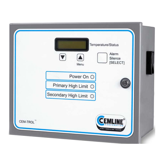
If either high temperature limits are exceeded the alarm horn will also sound and the alarm light(s) will light red. The CEM-TROL also features an alarm silence relay which will silence the alarm but not the fault light when the generator is being serviced. - Page 8 This feature is not functional when using a pilot operated valve with a self-contained temperature pilot. Built in LED/LCD display of functions and alarms: The CEM-TROL is designed for the user to tell at a glance how the system is operating. The built in LED displays make troubleshooting simple.
- Page 9 Built in contacts to notify BAS (Building Automation System) of functions and alarms: This control allows for simple and reliable interface from a remote location. The BAS can also start and stop the packaged water heater. BAS can remotely read the temperature in the packaged water heater via a 4 –...
-
Page 10: Contractor Wiring
Alarm approximately 103 db. NEMA 4 enclosure The Cemline CEM-TROL is a self contained board and can not be field repaired. For a replacement board contact Cemline Corporation at the address shown on page one of this manual. -
Page 11: Control Screens
Controller Screens Controller screens: There are three tactile keys on the front of the panel. The center key, labeled Menu ( ), is pushed to select the desired function. The right key, labeled Alarm Silence [SELECT], is pushed to access the desired screen. -
Page 12: Setting The Controller
Screen 13 Screen 14 Maximum Output Initial Settings Screen 15 Screen 16 Diagnostics About Screen 17 Quit After 60 seconds in any screen ”Home” screen will be displayed. Setting the Controller There are three tactile keys on the front of the panel. The center key, labeled Menu , is pushed to select the desired function. -
Page 13: Home Screen
SET: This is the operating temperature set point of the water heater. TEMP: This is the temperature reading of the water in the heater. CEM-TROL Version 3.2 and higher the display screen will be slightly different than above and is shown below:... -
Page 14: Alternative Home Screen
I-P transducer or an electronic control valve the temperature set point of the water heater will be selected using the CEM-TROL. This feature is not functional when using a pilot operated valve with self-contained temperature pilot. -
Page 15: Primary High Limit Temperature
CEM-TROL. See the Cemline Water Heater I O & M manual and the self-contained temperature pilot I O & M manual for setting the operating temperature. -
Page 16: Primary High Limit Temperature Reset Differential
Screen 4 High Limit 1 Degrees F [xxx] 3. Press “ ” key to change temperature setting in an increasing direction or press “ ” key to change the temperature setting in a decreasing direction until the desired high limit temperature appears on the screen. -
Page 17: Secondary High Limit Temperature
Secondary High Temperature Limit This is the secondary high limit temperature is typically set 20-30 F higher than the desired operating temperature. When the secondary high limit temperature is reached a solenoid opens to dump overheated water to drain. Be sure to pipe the outlet from this solenoid to drain. CAUTION: When using the self-contained temperature pilot DO NOT set the operating temperature greater than the primary or secondary high limit settings. -
Page 18: Control Valves
6. Press the [SELECT] key and the screen will read: Screen 6 Differential 2 Reset Deg F [xxx] 7. Press “ ” key to change temperature setting in an increasing direction or press “ ” key to change the temperature setting in a decreasing direction until the desired secondary high limit temperature differential appears on the screen. -
Page 19: Pid Gain Kp (Proportional)
Setting PID Gain Kp (Proportional) The operating controls are factory preset for optimal control of the water heater. The Kp (Proportional) is used to handle the present. Kp (proportional) is a constant used to send a signal to the output. The proportional control with a set point of 140 F and a proportional band of 10 would have a 100% output at 130 F, 50% output at 135... -
Page 20: Pid Gain Kd (Derivative)
4. Press [SELECT] key to place the setting in memory and return to the home screen. Remote Control The CEM-TROL can operate with a remote temperature set point. The remote temperature set point allows the Building Automation System (BAS) to supply a constant 4 – 20 mA signal to the controller. -
Page 21: Control Output
4. Press [SELECT] key to place the setting in memory and return to the home screen. Control Output The CEM-TROL has three output settings options. The output setting options are 0 – 10, 2 – 10, or a AIR VALVE. The 0-10 setting will output a 0-10 VDC control output signal to the control valve, the 2 –10 setting will output a 0-10 VDC control output signal to the control valve, and the... - Page 22 It is extremely important that the control signal of the control valve supplied and the “Control Output” listed in the CEM-TROL be the same. The water heater is factory shipped with the “Control Output” properly set for the supplied control valve’s actuator.
-
Page 23: Maximum Output
Maximum Output The CEM-TROL can be adjusted to limit the maximum output voltage being sent to the control valve. The maximum output setting can be set as 10, 9, 8, 7, 6, or 5 VDC. The maximum output setting is used to limit the maximum stroke of the control valve. The maximum output adjustment is only available when the “Control Signal”... -
Page 24: About
About This screen lists the version of the controller. When contacting the factory about the controller be sure to mention the version. 1. Press the [Menu] key fifteen (15) times and the following screen will appear: Screen 16 ABOUT 2. Press the [SELECT] key and the screen will read: Screen 16 ABOUT CEMLINE VER... -
Page 25: Terminal Board Layout
Terminal Board Layout... -
Page 26: Building Automation Control Interface
Building Automation System (BAS) Interface The CEM-TROL has built in contacts to interface with the building automation system (BAS). Remote On-Off: Terminal block P-1 is a four pole block with the two poles connected in series with the 24 VAC incoming power from the supply transformer. -
Page 27: Remote Temperature Read Out
Remote Temperature Read-Out (via a 4-20 mA signal): Terminal block P-3 (terminals 1-2) will output a 4-20 mA signal. This signal will be scaled as 4 mA = 32 F and 20 mA = 212 CAUTION: Terminal block P-3 terminals 1-2 are connected to an isolated chassis ground. -
Page 28: Testing The Temperature Sensor
6. Turn power back on. Cem-trol units version 2.0 and higher will display the below alarm status on the LCD screen if the temperature sensor(s) are not attached or are defective. In order to determine the version of the Cem-trol please refer to the ‘About’... -
Page 29: Wiring Diagram For Self-Contained Temperature Pilot Operated Control Valves
Wiring Diagram – Self-Contained Temperature Pilot Operated Control Valves... -
Page 30: Wiring Diagram For Pneumatically Operated Control Valves
Wiring Diagram – Pneumatic Operated Control Valves with I-P Transducer... -
Page 31: Wiring Diagram For Warren Controls With Amuract Actuator
Wiring Diagram – Warren Controls Valve - Amuract Actuator... -
Page 32: Wiring Diagram For Mxg And Mfx Valves
Wiring Diagram – MXG and MXF Valves... -
Page 33: Wiring Diagram For M2H And M3P Valves
Wiring Diagram – M2H and M3P Valves... -
Page 34: Wiring Diagram For Mvf Valves
Wiring Diagram – MVF Valves... -
Page 35: Mxg And Mxf Valve Information
MXG and MXF Valve Information The MXG and MXF valves can be configured for linear and equal percentage operation. Factory setting is equal percentage. Switch Characteristic Linear Equal percentage * Control signal — must be in the OFF position Volts or mA — must be in the OFF position Valve Calibration The MXG and MXF valves are factory-calibrated at 0% and 100% stroke. - Page 36 Warning The control valve has a hand wheel knob on the top of the valve (see diagram below). This control knob must be placed into the automatic position (AUTO). The AUTO position allows automatic control of the valve to occur. By placing the hand wheel in the OFF position the valve will not close. Do not place the wheel in the manual position.
-
Page 37: M3P And M2H Valve Information
M3P and M2H Valve Information Valve Calibration The M3P and M2H valves are factory-calibrated at 0% and 100% stroke. When commissioning the valves, however, (especially under extreme conditions of use) there may still be some leakage via control path 1 —>2 for the M2H and 1 —>3 for the M3P (see below, and marked on the valve) with a 0% stroke control signal (DC 0V, DC 4 mA or DC 2 V). -
Page 38: Mvf Valve Information
MVF Valve Information The MVF valve can be configured for linear and equal percentage operation. Factory setting is equal percentage. Status green calib. / Man Calib. Status error calib. error 2 ... 20 V 4 ... 20 mA [mA] Switch Volts or mA —... - Page 39 Indication Operating Remarks, Troubleshooting State, Function Control mode Normal operation; everything OK. Flashing Calibration Wait until calibration is finished (green or red LED will be lit) Green In manual Hand wheel in Man or Off position control Calibration error Recalibrate (bridge contacts behind the calibration slot) Internal error Replace electronics module...
-
Page 40: General Valve Information
Check one of above terminals to ground. The resistance should be infinite. Measure the voltage at 24 volt transformer between points 7 and 12 as seen on the wiring diagram from page 7. Reconnect the control module. Reconnect the power to the CEM-TROL. -
Page 41: Magnetic Coil Resistance Information
Magnetic Coil Resistance Information Actuator Coil Valve Model Resistance ( ) M2H15F M2H20FY M2H25FY M2H32FY 15.3 M2H40FY M2H50FY M3P80FY 5.187 M3P100FY 3.34 1) Magnetic Coil Resistance (KI. 7+8) . Remove the screws from the top of the electrical housing on the control valve and remove the cover. -
Page 42: Warren Controls Amuract Actuator Valve Information
Warren Controls AmurAct Valve Information For complete information on the Warren Valve and Actuator see the Warren Controls Amuract Actuator Linkage and Motor Installation, Operation, & Maintenance Manual supplied with the unit. The IOM manual is installed inside a plastic envelope adhered to the inside of the safety shield of the AmurAct linkage, otherwise the manual can be found online at www.amuract.com. - Page 43 Turn OFF the Cem-trol controller via the on / off switch on the side of the unit. Close the steam or hot water isolation valves to the unit. Verify the linkage safety covers are in place. Remove the screws from the top of the electrical housing on the control valve and remove the cover.
- Page 44 ® Cemline Corporation P. O. Box 55, Cheswick, PA, 15024 Phone: (724) 274-5430 • FAX (724) 274-5448 www.cemline.com...
Need help?
Do you have a question about the CEM-TROL and is the answer not in the manual?
Questions and answers