Table of Contents
Advertisement
Advertisement
Table of Contents

Related Manuals for GearRev Kinematics

Summary of Contents for GearRev Kinematics
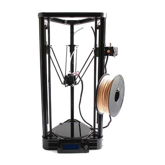
- Page 1 KINEMATICS 3D PRINTER MANUAL...
-
Page 3: Table Of Contents
CONTENTS TOOLS NEEDED FOR ASSEMBLY TOOLS NEEDED FOR ASSEMBLY ASSEMBLY OF THE TOP VORTEX ASSEMBLY OF THE BOTTOM VERTEX ASSEMBLY OF AXIS MOTORS ASSEMBLY OF LONG LONG V RAILS ASSEMBLY OF THE EFFECTOR ASSEMBLY OF THE BELT CONNECTOR PIECES ASSEMBLY OF TOP VERTEX ON THE FRAME ASSEMBLY OF THE BELT ASSEMBLY OF THE FILAMENT EXTRUDER ASSEMBLY OF THE LCD SCREEN... -
Page 4: Assembly Of The Top Vortex
REFERENCE PAGE FOR PARTS ASSEMBLY OF THE TOP VORTEX Materials needed for assembly Short V rails (3) Top vertex (3) M2.5*16mm screw M4*30mm screw M4 nut M4 Square nut (12) M4*10 screw (12) M4 square nut Step 1 This filler head Hexagonal groove is at the top side at bottom... - Page 5 Step 5 Step 2 Lay the top vertex on a flat surface. The side Materials needed for assembly with the hexagonal groove being on bot- tom. Slide short short V rail in the flank of M3 nut (3) 608 bearing the vertex.
-
Page 6: Assembly Of The Bottom Vertex
ASSEMBLY OF THE BOTTOM VERTEX Step 2 Before sliding together the short V rails, Materials needed for assembly attach the Makeboard to one of the short V rails using 2 M4*8 screws and M4 square M4*10 screws (30) nuts. Make sure the mounting holes on the M4 square nuts (32) side of the USB input are used to mount the Makeboard (See Figure 1.9). -
Page 7: Assembly Of Axis Motors
3mm distance between the top Axis stepper motor (3) of the stepper motor shaft and the stepper gear). M3*8 screws (12) Ensure that the set screw is tight. GearRev recommends the application of thread lock Step 1 on the set screws. Step 4 Take a stepper motor and place a timing wheel on the shaft of the motor. -
Page 8: Assembly Of Long Long V Rails
ASSEMBLY OF LONG LONG V RAILS Step 6 Position 4 M3*8 screws in the coordinating Materials needed for assembly holes and begin to screw manually first to avoid damage to motor. Long V rails (3) Terminal block (3) Step 7 limit switches (3) M4 square nut (3) Use a 2.5 allen key against the grooves in... - Page 9 Step 2 Step 4 Linear rails Long V rails Assemble the three linear rails with sliders Insert three 2020*680mm long V rails to by attaching 4 M3*8 screws and 4 M3 T nuts their corresponding slots in the bottom to each rail (Figure 3.6). vertex.
-
Page 10: Assembly Of The Effector
Step 5 ASSEMBLY OF THE EFFECTOR Secure Materials needed for assembly Slide the linear rails onto the long V rail The auto-alignment effector user materials M4*30 screw (1) Assembled nozzle (1) grooves, securing them temporarily while we attach the limit switch in place. M2.5*16 screw (2) Spring (1) Heating wire (1) - Page 11 Step 3 Step 2 Limit External part Limit switch Switch Jig of Print Internal part Head Cover the assembled nozzle with the inter- Insert the limit switch wires into the big hole nal part and place it inside the external part of the external part with the wires coming out of the back end, Groove...
- Page 12 Step 6 Step 4 Heat block Fan groove Fan groove Fans Add the fan groove to the bottom of the Finally, add on two fans on either side of the external part using 2 M3*8 screws in the external effector, with the fan labels facing corresponding holes (Figure 5.2) inside.
-
Page 13: Assembly Of The Belt Connector Pieces
Step 2 ASSEMBLY OF THE BELT CONNECTOR PIECES Belt tensioner M4 copper spacer Belt tensioner M3 nuts in Materials needed for assembly grooves Secure the belt tensioner on the opposite Carbon fiber rods (6) end to the carbon fibre rods similar to the effector. -
Page 14: Assembly Of Top Vertex On The Frame
Step 3 ASSEMBLY OF TOP VERTEX ON THE FRAME Attach tensioner to linear rail Linear rail slider Materials needed for assembly Mount belt tensioner to the linear rail slider M4*25 screw (3) by securing 4 M3*12 screws in their corre- sponding holes (see figure 5.12) M4 square nut (3) Repeat steps for remaining belt tensioners. -
Page 15: Assembly Of The Belt
ASSEMBLY OF THE BELT The other end of the belt will wrap around the second chamber. Make sure the belt is tight when securing it in. (See figure 7.4) Materials needed for assembly Finally install the belt spring to the belt to ensure optimal tension. -
Page 16: Assembly Of The Filament Extruder
Step 2 ASSEMBLY OF THE FILAMENT EXTRUDER Jig of the filament feeder M3*20 Assemble the jig of the filament extrud- Materials needed for assembly screws Washer and er with the bearing located in the middle. M3 Nut Frame of the filament extruder (1) Quick acting plug (1) Secure the bearing in place using an M3*20 screw, washer and an M3 nut (see figure... -
Page 17: Assembly Of The Lcd Screen
Step 4 ASSEMBLY OF THE LCD SCREEN Mounting and PTFE tube Materials needed for assembly Assemble 2 groups of M4*10 screws and PTFE tube end M4 t nuts to the holes of the flank. LCD screen (1) PTFE tube end Mount the Filament extruder assembly to LCD screen LCD housing (1) -
Page 18: Assembly And Wiring Of Make Board
Step 3 ASSEMBLY AND WIRING OF MAKEBOARD M4*10 screws and nuts on wither end of LCD screen Use the toggle to cover the knob of the LCD screen (figure 9.3) Step 1 Take the end wire of each axis limit switch, and insert it into the 2 pin connector (figure Step 4 10.1). -
Page 19: Wiring Of The Axis Motors & Limit Switches
Step 3 WIRING OF THE AXIS MOTORS & LIMIT SWITCHES Connect LCD wires EXP 1 EXP 2 Connect LCD wires EXP1 and EXP2 to their Makeboard at Step 1 bottom for wiring corresponding connectors on the make- Axis X board located beside the YXZ-axis stop First, we must label the axis. -
Page 20: Assembly Of The Print Platform
ASSEMBLY OF THE PRINT PLATFORM POWER SUPPLY Materials needed for assembly Warning Do not power the PSU until wiring is completed. Bed clips (3) Step 1 Heated bed (1) L port and N port Glass plate (1) Start by loosening screws L and N (AC) on M3*12 screws (3) the front of the power box (see figure 13.1) M3 T nuts (3) -
Page 21: Makeboard Outlet Cover And Filament Holder
4 M4 square nuts, and M4*8 screws (See figure 14.1) ur support page also inCludes other downloads that will help you get Figure 14.1 familiar with your kinematiCs d printer Step 2 Filament holder Using 2 M4*8 screw and 2 M4 t nuts, attach...
Need help?
Do you have a question about the Kinematics and is the answer not in the manual?
Questions and answers