Table of Contents
Advertisement
FST 500 Manual
Thank you for choosing ANYHZ‟s high-performance FST-500 Series. The FST-500 Series is
manufactured with high-quality components and materials and incorporate the latest
microprocessor technology available.
This manual is to be used for the installation, parameter setting, troubleshooting, and daily
maintenance of the AC motor drive. To guarantee safe operation of the equipment, read the following
safety guidelines before connecting power to the AC motor drive. Keep this operating manual at hand
and distribute to all users for reference.
To ensure the safety of operators and equipment, only qualified personnel familiar with AC motor drive
are to do installation, start-up and maintenance Always read this manual thoroughly before using
FST-500 series AC Motor Drive, especially the WARNING, DANGER and CAUTION notes.
Failure to comply may result in personal injury and equipment damage. If you have any questions,
please contact your dealer.
PLEASE READ PRIOR TO INSTALLATION FOR SAFETY.
*******************************************************************************************************************
1. AC input power must be disconnected before any wiring to the AC motor drive is made.
2. A charge may still remain in the DC-link capacitors with hazardous voltages, even if the power has
been turned off. To prevent personal injury, please ensure that power has turned off before
opening the AC motor drive and wait ten minutes for the capacitors to discharge to safe voltage
levels.
3. Never reassemble internal components or wiring.
4. The AC motor drive may be destroyed beyond repair if incorrect cables are connected to the
input/output terminals. Never connect the AC motor drive output terminals U/T1, V/T2, and W/T3
directly to the AC mains circuit power supply.
5. Ground the FST-500 using the ground terminal. The grounding method must comply with the laws
of the country where the AC motor drive is to be installed. Refer to the Basic Wiring Diagram.
6. FST-500 series is used only to control variable speed of 3-phase induction motors, NOT for
1-phase motors or other purpose.
7. FST-500 series shall NOT be used for life support equipment or any life safety situation.
PREFACE
- Page 1 -
Advertisement
Table of Contents

Summary of Contents for ANYHZ FST-500 Series
-
Page 1: Preface
5. Ground the FST-500 using the ground terminal. The grounding method must comply with the laws of the country where the AC motor drive is to be installed. Refer to the Basic Wiring Diagram. 6. FST-500 series is used only to control variable speed of 3-phase induction motors, NOT for 1-phase motors or other purpose. - Page 2 FST 500 Manual ******************************************************************************************************************! 1. DO NOT use Hi-pot test for internal components. The semi-conductor used in AC motor drive easily damage by high-voltage. 2. There are highly sensitive MOS components on the printed circuit boards. These components are especially sensitive to static electricity. To prevent damage to these components, do not touch these components or the circuit boards with metal objects or your bare hands.
-
Page 3: Table Of Contents
FST 500 Manual Table of Contents PREFACE ................................... 1 Table of Contents ................................. 3 Chapter 1 Introduction ............................... 6 1.1.1 Nameplate Information ........................... 7 1.1.2 Model Explanation ............................. 7 1.1.3 External Parts and Labels ..........................8 1.1.4 Remove instructions ............................9 1.2 Preparation for Installation and Wiring ...................... - Page 4 FST 500 Manual 3.3 Trial Run ................................30 Chapter 4 Parameters ............................... 32 4.1 Summary of Parameter Settings ........................32 4.2 Parameter Settings for Applications ......................41 4.3 Description of Parameter Settings........................ 46 Chapter 5 Troubleshooting ............................. 110 5.1 Over Current (OC) ............................110 5.2 Ground Fault ................................111 5.3 Over Voltage (OV) .............................111 5.4 Low Voltage (Lv) ..............................
- Page 5 FST 500 Manual Appendix A Specifications ............................128 Appendix B Accessories ............................132 B.1 All Brake Resistors & Brake Units Used in AC Motor Drives ............132 B.1.1 Dimensions and Weights for Brake Resistors& Brake Units ............133 B.2 Non-fuse Circuit Breaker Chart ........................136 B.3 Fuse Specification Chart ..........................
-
Page 6: Chapter 1 Introduction
FST 500 Manual Chapter 1 Introduction The AC motor drive should be kept in the shipping carton or crate before installation. In order to retain the warranty coverage, the AC motor drive should be stored properly when it is not to be used or an extended period of time. -
Page 7: Nameplate Information
FST 500 Manual 1.1 Receiving and Inspection This FST-500 AC motor drive has gone through rigorous quality control tests at the factory before shipment. After receiving the AC motor drive, please check for the following: Check to make sure that the package includes an AC motor drive, the User Manual/Quick Start and CD, and rubber bushings. -
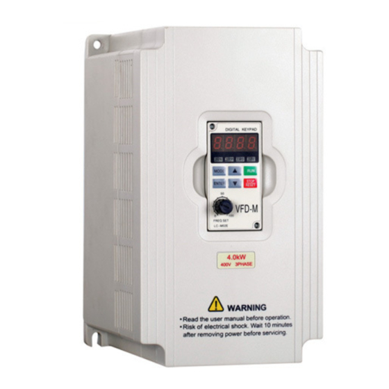
Page 8: External Parts And Labels
FST 500 Manual 1.1.3 External Parts and Labels - Page 8 -... -
Page 9: Remove Instructions
FST 500 Manual 1.1.4 Remove instructions - Page 9 -... -
Page 10: Preparation For Installation And Wiring
FST 500 Manual 1.2 Preparation for Installation and Wiring 1.2.1 Ambient Conditions Install the AC motor drive in an environment with the following conditions: -10 ~ +50° C (14 ~ 122° F) for UL & cUL Operation Temperature: -10 ~ +40° C (14 ~ 104° F) for 5.5kw models and above Relative <90%, no condensation allowed Humidity:... -
Page 11: Minimum Mounting Clearances
FST 500 Manual 1.2.2 Minimum Mounting Clearances ******************************************************************************************************************! 1. Operating, storing or transporting the AC motor drive outside these conditions may cause damage to the AC motor drive. 2. Failure to observe these precautions may void the warranty! 3. Mount the AC motor drive vertically on a flat vertical surface object by screws. Other directions are not allowed. -
Page 12: Dimensions
FST 500 Manual 1.3 Dimensions Model name D1 FST-500-0R4S2/T2, 85.0 74.0 141.5 130.5 10.0 113.0 10.0 FST-500-0R7S2/T2 [3.35] [2.91] [5.57] [5.14] [0.39] [4.45] [0.39] FST-500-1R5S2/T2 100.0 89.0 151.0 140.0 10.0 10.0 10.0 FST-500-0R7T4 [3.94] [3.50] [5.94] [5.51] [0.39] [0.39] [0.39] FST-500-1R5T4 FST-500-2R2T4 - Page 12 -... - Page 13 FST 500 Manual Model Name FST-500-2R2S2 125.0 110.0 220.0 205.0 15.0 166.3 FST-500-3R7T2/T4 [4.92] [4.33] [8.66] [8.07] [0.59] [6.55] [0.32] FST-500-5R5T2/T4 FST-500-7R5T4 ***************************************************************************************************************** - Page 13 -...
-
Page 14: Chapter 2 Installation And Wiring
Refer to the technical data label affixed to the AC motor drive and the motor nameplate for electrical data. The "Line Fuse Specification" in Appendix B, lists the recommended fuse part number for each FST-500 Series part number. These fuses (or equivalent) must be used on all installations where compliance with U.L. standards is a required ******************************************************************************************************************! Make sure that power is only applied to the R/L1, S/L2, T/L3 terminals. -
Page 15: Basic Wiring Diagram
FST 500 Manual ******************************************************************************************************************! 1. A charge may still remain in the DC bus capacitors with hazardous voltages even if the power has been turned off. To prevent personal injury, please ensure that the power is turned off and wait ten minutes for the capacitors to discharge to safe voltage levels before opening the AC motor drive. - Page 16 9. Use ground leads that comply with local regulations and keep them as short as possible. 10. No brake resistor is built in the FST-500 series, it can install brake resistor for those occasions that use higher load inertia or frequent start/stop. Refer to Appendix B for details.
- Page 17 FST 500 Manual ******************************************************************************************************************! - Page 17 -...
-
Page 18: External Wiring
FST 500 Manual 2.2 External Wiring Items Explanations Power Please follow the specific power supply supply requirement shown in APPENDIX A. Fuse/NFB There may be inrush current during (Optional) power up. Please check the chart of APPENDIX B and select the correct fuse with rated current. -
Page 19: Main Circuit
FST 500 Manual 2.3 Main Circuit 2.3.1 Main Circuit Connection Terminal Symbol Explanation of Terminal Function R/L1, S/L2, T/L3 AC line input terminals (three phase) U/T1, V/T2, W/T3 Motor connections B1 – B2 Connections for brake resistor (optional) Earth Ground ******************************************************************************************************************! Mains power terminals (R/L1, S/L2, T/L3) ... - Page 20 When it needs to install the filter at the output side of terminals U/T1, V/T2, W/T3 on the AC motor drive. Please use inductance filter. Do not use phase-compensation capacitors or L-C (Inductance-Capacitance) or R-C (Resistance-Capacitance), unless approved by ANYHZ. ...
-
Page 21: Main Circuit Terminals
FST 500 Manual 2.3.2 Main Circuit Terminals Wire Type: 75 oC Copper Only Max. Wire Torque Current Gauge kgf-cm Model Name (input / (in-lbf) output) FST-500-0R 6.3A/2.5A FST-500-0R 3.2A/2.5A 12-14 FST-500-0R 11.5A/5.0A (3.3-2.1) (12) FST-500-0R 6.3A/5.0A FST-500-1R 15.7A/7.0A 12 (3.3) FST-500-1R 9.0A/7.0A 12-14... -
Page 22: Control Terminal Wiring (Factory Settings)
FST 500 Manual 2.4 Control Terminal Wiring (Factory Settings) - Page 22 -... - Page 23 FST 500 Manual Terminal symbols and functions Terminal Symbol Terminal Function Factory Settings (NPN mode) RA-RC Resistive Load Multi-Function Relay Output 5A(N.O.)/3A(N.C.) 277Vac; (N.O.) a 5A(N.O.)/3A(N.C.) 30Vdc Refer to P45 for programming. RB-RC Resistive Load Multi-Function Relay Output 5A(N.O.)/3A(N.C.) 277Vac; (N.C.) b 5A(N.O.)/3A(N.C.) 30Vdc 5A(N.O.)/3A(N.C.) 277Vac;...
- Page 24 FST 500 Manual Terminal Symbol Terminal Function Factory Settings (NPN mode) Analog Output Meter 0 to 10V, 2mA Impedance: 100kΩ Output Current: 2mA max Resolution: 8 bits Range: 0 ~ 10Vdc Maximum: 48Vdc, 50mA Refer to P45 for programming. Multi-function Output Terminal (Photocoupler) Multi-function Output Common Common for Multi-function Outputs...
- Page 25 FST 500 Manual Digital inputs (M0~M5) When using contacts or switches to control the digital inputs, please use high quality components to avoid contact bounce. Digital outputs (MO1) Make sure to connect the digital outputs to the right polarity, see wiring diagrams. ...
-
Page 26: Chapter 3 Keypad And Start Up
FST 500 Manual Chapter 3 Keypad and Start Up 3.1 Keypad 3.1.1 Description of the Digital Keypad The digital keypad includes two parts: Display panel and keypad. The display panel provides the parameter display and shows the operation status of the AC drive and the keypad provides programming and control interface. -
Page 27: How To Operate The Digital Keypad Lc-M02E
FST 500 Manual 3.1.2 How to Operate the Digital Keypad LC-M02E - Page 27 -... -
Page 28: Lc-M02E
FST 500 Manual 3.1.3 LC-M02E Reference Table for the 7-segment LED Display of the Digital Keypad - Page 28 -... - Page 29 FST 500 Manual Digital Keypad – Mounting Panel A Unit mm [inch] Digital Keypad – Mounting Panel B Unit mm [inch] - Page 29 -...
-
Page 30: Operation Method
FST 500 Manual 3.2 Operation Method The operation method can be set via control terminals and LC-M02E keypad. Please choose a suitable method depending on application and operation rule. 3.3 Trial Run The factory setting of the operation source is from the digital keypad (Pr.01=00). You can perform a trial run by using the digital keypad with the following steps: 1. - Page 31 FST 500 Manual If the results of trial run are normal, please start the formal run. NOTE 1、 Stop running immediately if any fault occurs and refer to the troubleshooting guide for solving the problem. 2、 Do NOT touch output terminals U, V, W when power is still applied to L1/R, L2/S, L3/T even when the AC motor drive has stopped.
-
Page 32: Chapter 4 Parameters
FST 500 Manual Chapter 4 Parameters This FST-500 AC motor drive has 157 parameters for easy setting. In most applications, the user can finish all parameter settings before start-up without the need for re-adjustment during operation. 4.1 Summary of Parameter Settings ※... - Page 33 FST 500 Manual Factory Parameter Explanation Settings Setting Pr.08 Minimum Output Freq 0.10 to 20.00Hz 1.50 115V/230V: 0.1 to 255.0V 10.0 Minimum Output Pr.09 460V: 0.1 to 510.0V 20.0 Voltage 575V: 0.1 to 637.0V 26.1 ※Pr.10 Acceleration Time 1 0.1 to 600.0 sec or 0.01 to 600.0 sec 10.0 ※Pr.11 Deceleration Time 1...
- Page 34 FST 500 Manual Factory Parameter Explanation Settings Setting DC Braking during Pr.30 0.0 to 25.0 sec Stopping Start-point for DC Pr.31 0.00 to 60.00 Hz 0.00 Braking 00: Stop operation after momentary power loss 01: Continues after momentary power loss, speed Momentary Power search starts with Master Frequency Pr.32...
- Page 35 FST 500 Manual Factory Parameter Explanation Settings Setting 30: One-Shot PLC Run 31: Index input signal 32:Counter Incremented by Drive Output Frequency 00: Analog Frequency Meter (0 to Maximum Output Frequency) 01: Analog Current Meter (0 to 250% of the rated AC ※Pr.43 Analog Output Signal drive current)
- Page 36 FST 500 Manual Factory Parameter Explanation Settings Setting Pr.56 Reserved Pr.57 AC Drive Rated Current Display (unit: 0.1A) ##.# 00: Standard Motor (self cool motor) Electronic Thermal Pr.58 01: Inverter Motor (auxiliary cool fan on motor) Overload Relay 02: Inactive Electronic Thermal 30 to 300 sec ※Pr.59...
- Page 37 FST 500 Manual Factory Parameter Explanation Settings Setting 00: No fault occurred Pr.73 Present Fault Record 01: Over-current (oc) 02: Over-voltage (ov) Second Most Recent Pr.74 03: Overheat (oH) Fault Record 04: Overload (oL) 05: Overload 1 (oL1) 06: External Fault (EF) 07: CPU failure 1 (CF1) 08: CPU failure 3 (CF3) 09: Hardware Protection Failure (HPF)
- Page 38 FST 500 Manual Factory Parameter Explanation Settings Setting 00: 4800 bps 01: 9600 bps Pr.89 Transmission Speed 02: 19200 bps 03: 38400 bps 00: Warn and Continue Operating Transmission Fault 01: Warn and RAMP to Stop Pr.90 Treatment 02: Warn and COAST to Stop 03: Keep Operation without Warning 0.0: Disable Pr.91...
- Page 39 FST 500 Manual Factory Parameter Explanation Settings Setting Vector Slip Pr.108 25 to 9999 (per 2ms) Compensation Filter Selection for Zero 00: No output Pr.109 Speed Control 01: Control by DC voltage Voltage of Zero Speed Pr.110 0.0 to 20.0 % of Max. output voltage (Pr.05) Control Pr.111 Decel S-curve...
- Page 40 FST 500 Manual Factory Parameter Explanation Settings Setting Minimum Reference Pr.128 0.0 to 10.0 V Value Maximum Reference Pr.129 0.0 to 10.0 V 10.0 Value Invert Reference 00: Not inverted Pr.130 Signal AVI (0-10V) 01: Inverted Minimum Reference Pr.131 0.0 to 20.0mA Value (4-20mA) Maximum Reference Pr.132...
-
Page 41: Parameter Settings For Applications
Pr.155 Coefficient for Motor 0.1 to 5.0 (recommended setting d2.0) Instability Communication Pr.156 0 to 200 (x500us) Response Delay Time Communication Mode 0: ANYHZ ASCII Pr.157 Selection 1: Modbus 4.2 Parameter Settings for Applications Speed Search Related Applications Purpose Functions... - Page 42 FST 500 Manual Multi-step Operation Related Applications Purpose Functions Parameters Conveying Cyclic operation by To control 7-step speeds and duration Pr.17~Pr.23 machinery multi-step speeds. by simple contact signals. Pr.78~Pr.79 Pr.81~Pr.87 Switching acceleration and deceleration time Related Applications Purpose Functions Parameters Auto turntable for Switching When an AC motor drive drives two or...
- Page 43 FST 500 Manual Operation Command Related Applications Purpose Functions Parameters General application Selecting the Selection of AC motor drive control by Pr.01 source of control external terminals or digital keypad. Pr.39~Pr.42 signal Frequency Hold Related Applications Purpose Functions Parameters General application Acceleration/ Hold output frequency during Pr.39~Pr.42...
- Page 44 FST 500 Manual Over-torque Setting Related Applications Purpose Functions Parameters Pump and fan Control the motor When user cannot provide Pr.36 speed within upper/lower limit, gain or bias from Pr.37 upper/lower limit external signal, it can be set individually in AC motor drive. Skip Frequency Setting Related Applications...
- Page 45 FST 500 Manual Output signal for Over-torque Related Applications Purpose Functions Parameters Pumps, fans and To protect When over-torque is detected, a Pr.45 extruders machines and to signal is given to prevent machines Pr.46 have continuous/ from damage. Pr.61 reliable operation Pr.62 Output Signal for Low Voltage Related...
-
Page 46: Description Of Parameter Settings
FST 500 Manual 4.3 Description of Parameter Settings ※This parameter can be set during operation. Pr..00 ※ Source of Frequency Command Factory Setting: 00 Settings 00 Master Frequency determined by digital keypad. (LC-M02E) 01 Master frequency determined by 0 to +10 V input 02 Master frequency determined by 4 to 20mA input 03 Master frequency determined by RS-485 Communication port 04 Master frequency determined by potentiometer on digital keypad. - Page 47 FST 500 Manual Note: The motor stop method is usually determined by the application or system requirements. Pr.03 Maximum Output Frequency Unit: 0.1Hz Settings 50.00 to 400.0 Hz Factory Setting: 60.00 ★ This parameter determines the AC drive‟s Maximum Output Frequency. All the AC drive analog inputs (0 to +10V, 4 to 20mA) are scaled to correspond to the output frequency range.
- Page 48 FST 500 Manual Pr.06 Mid-Point Frequency Unit: 0.1Hz Settings 0.10 to 400.0Hz Factory Setting: 1.50 ★ The parameter sets the Mid-Point Frequency of V/F curve. With this setting, the V/F ratio between Minimum Frequency and Mid-Point frequency can be determined. Setting of this parameter must be equal to or greater than Minimum Output Frequency (Pr.08) and equal to or less than Maximum Voltage Frequency (Pr.04).
- Page 49 FST 500 Manual Commonly used V/F Setting (1) General Purpose - Page 49 -...
- Page 50 FST 500 Manual (2) Fans and Pumps (3) High Starting Torque Pr.10 ※ Acceleration Time 1 Unit: 0.1 or 0.01 sec Pr.11 ※Deceleration Time 1 Unit: 0.1 or 0.01 sec Pr.12 ※Acceleration Time 2 Unit: 0.1 or 0.01 sec Pr.13 ※ Deceleration Time 2 Unit: 0.1 or 0.01 sec Settings 0.1 to 600.0 sec or 0.01 to 600.0 sec Factory Setting: 10.0...
- Page 51 FST 500 Manual Pr.14 Acceleration S-Curve Settings 00 to 07 Factory Setting: 00 ★This parameter is used whenever the motor load needs to be accelerated or decelerated smoothly. The desired accel/decel effect is selectable from 0 to 7, in which the larger the number, the greater the effect achieved.
- Page 52 FST 500 Manual Pr.16 ※Jog Frequency Unit: 0.1 Hz Settings 0.00 to 400.0 Hz Factory Setting: 6.00 Hz ★ When the JOG function is activated, the AC drive will accelerate from Minimum Output Frequency (Pr.08) to Jog Frequency (Pr.16). Drive must be in “stop” status for the operator to activate the JOG function.
- Page 53 FST 500 Manual Pr.24 Reverse Operation Inhibition Factory Setting: 00 Settings 00 Enable REV operation 01 Disable REV operation ★ This parameter is used to disable motor rotation in reverse. Pr.25 Over–Voltage Stall Prevention Settings 115V/230V series 330-450Vdc Factory Setting: 390 460V series 660-900Vdc Factory Setting: 780...
- Page 54 FST 500 Manual constant output frequency. Drive will resume accelerating only after the current drops below the setting for Pr.26. Pr.27 Over-Current Stall Prevention during Operation Unit: 1% Factory Setting: 150% Settings 20 to 200% 00: disable ★During a steady-state operation with the motor load rapidly increasing, the AC drive output current may exceed the limit specified in Pr.27.
- Page 55 FST 500 Manual Pr.30 DC Braking Time during Stopping Unit: 0.1sec Settings 0.0 to 25.0 sec Factory Setting: 0.0 ★ This parameter determines the duration for the DC Braking voltage to be applied during stopping. If stopping with DC Braking is desired, then Pr.02 must be set to Ramp to Stop (0.0). Pr.31 Start-Point for DC Braking Unit: 0.1sec Settings 0.00 to 60.00Hz...
- Page 56 FST 500 Manual Pr.33 Maximum Allowable Power Loss Time Unit: 0.1sec Settings 0.3 to 5.0 sec Factory Setting: 2.0 sec ★ After a power loss, the AC drive will resume operation only if the power loss duration is shorter than the time defined by Pr.33. If the Maximum Allowable Power Loss Time is exceeded, the AC drive output is then turned off.
- Page 57 FST 500 Manual Pr.36 Upper Bound of Output Frequency Unit: 0.1Hz Settings 0.10 Hz to 400.0 Hz Factory Setting: 400 ★ The Upper/Lower Bounds help prevent operation error and machine damage. ★ If the Upper Bound of Output Frequency is 50Hz and the Maximum Output Frequency is 60Hz, the Maximum Output Frequency will be limited to 50Hz.
- Page 58 FST 500 Manual 01: Two wire operation: Only Pr.38 can be set to “1”. Note: Multi-function Input Terminal M0 does not have its own parameter designation. M0 must be used in conjunction with M1 to operate two and three wire control. 02 Three Wire Control: Only Pr.38 can be set to “2”.
- Page 59 FST 500 Manual External Fault (N.O.) Parameter values 3 and 4 program Multi-Function Input Terminals: M1 (Pr.38), M2 (Pr.39), M3 (Pr.40), M4 (Pr.41) or M5 (Pr.42) to be External Fault (E.F.) inputs. External Fault (N.C.) Note: When an External Fault input signal is received, the AC drive output will turn off, drive will display “...
- Page 60 FST 500 Manual Parameter value 09 programs Multi-Function Input Terminal:M1 (Pr.38), M2 (Pr.39), M3 (Pr.40), M4 (Pr.41) or M5 (Pr.42) for Jog control. Jog Operation Note: Jog operation programmed by 9 can only be initiated while the motor is stop. (Refer to Pr.15, Pr.16.) Parameter value 10 programs Multi-Function Input Terminal: M1 (Pr.38), M2 (Pr.39), M3 (Pr.40), M4 (Pr.41) or M5 (Pr.42) for Accel/Decel Inhibit.
- Page 61 FST 500 Manual Selection Terminal: M1 (Pr.38), M2 (Pr.39), M3 (Pr.40), M4 (Pr.41) or M5 (Pr.42) for selecting the First or Second Accel/Decel time. (Refer to Pr.10 to Pr.13.) External Base Parameter values 12, 13 program Multi-Function Input Block (N.O.) Terminals: M1 (Pr.38), M2 (Pr.39), M3 (Pr.40), M4 (Pr.41) or M5 (Pr.42) (Normally Open for external Base Block control.
- Page 62 FST 500 Manual Parameter value 16 programs Multi-Function Input Run PLC Program Terminal:M1 (Pr.38), M2 (Pr.39), M3 (Pr.40), M4 (Pr.41) or M5 (Pr.42) to enable the AC drive internal PLC program. Parameter value 17 programs an input terminal to pause the PLC program. Pause PLC Program Note: Pr.17 to Pr.23, Pr.78, Pr.
- Page 63 FST 500 Manual Enter value (20) to disable any Multi-Function Input Terminal:M1 (Pr.38), M2 (Pr.39), M3 (Pr.40), M4 (Pr.41) or M5 (Pr.42) No Function Note: Purpose of this function is to isolate unused Multi-Function Input Terminals. Any unused terminals should be programmed to 20 to insure they have no effect on drive operation.
- Page 64 FST 500 Manual Factory Setting: 00 Settings 00 Analog Frequency Meter (0 to Maximum Output Frequency) 01 Analog Current Meter (0 to 250% of the rated AC drive current) 02 Feedback Signal (0 - 100%) 03 Output Power (0 - 100%) ★...
- Page 65 FST 500 Manual Maximum Output Terminal output is activated when the AC drive attains Maximum Frequency Attained Output Frequency. Terminal output is activated when Command Frequency is Zero speed lower than the Minimum Output Frequency. Terminal output is activated when over-torque is detected. Over-Torque detection Parameter Pr.61 determines the Over-Torque detection level.
- Page 66 FST 500 Manual The contact will be “close” before 90°C. Over Heat supervision The contact will be “close” before exceeding the setting of Over Current stall supervision P26/P27. Over Voltage stall The contact will be “close” before exceeding the setting of P25. supervision The contact will be “close”...
- Page 67 FST 500 Manual Pr.48※Adjust Bias of External Input Frequency Unit: 0.1Hz Settings 0.00 to 200.0% actory Setting: 0.00 Hz ★ This parameter provides a frequency offset when the source of frequency command is the analog input. Pr.49※Potentiometer Bias Polarity Factory Setting: 00 Settings 00 Positive Bias 01 Negative Bias ★This parameter sets the potentiometer Bias Frequency to be positive or negative.
- Page 68 FST 500 Manual Example 1: Set Pr.00=1 to command frequency with the potentiometer on keypad or Pr.00=2 (4 to 20mA current signal) potentiometer/current signal of external terminal. Example 2: A Bias Adjustment (16.7% of 60Hz) determines the Output Frequency to be 10 Hz with the potentiometer set at 0V as shown.
- Page 69 FST 500 Manual Example 3: The whole scale of the potentiometer may be used as desired. In addition to the signals 0 to 10V and 4 to 20mA, other popular voltage signals include 0 to 5V, 20 to 4mA or that under 10V. Example 4: This example shows how to use Gain to set a potentiometer range of 0 to 5 Volts for 0-60 Hz.
- Page 70 FST 500 Manual Example 5: In this example, a 6 Hz (10% of 60 Hz) negative bias is used. This setting is used to provide a noise margin (1V in this example) in noisy environments. Note that the top frequency is reduced to 54 Hz. Example 6: This example also uses negative bias and includes a potentiometer frequency gain to allow the AC drive to reach the Maximum Output Frequency.
- Page 71 FST 500 Manual Example 8: This example shows how to set up the “anti-slope”, which is an inversely proportional variation of frequency to the input analog signal, required for some applications in process control. A sensor will generate a large signal (such as 20mA or 10V) and the AC Drive will slow or stop. Pr.52※Motor Rated Current Unit: 0.1A Settings 30.0% FLA to 120.0% FLA...
- Page 72 FST 500 Manual Pr.55※Slip Compensation Settings 0.00 to 10.00 Factory Setting: 0.00 ★This parameter can be used to compensate motor slip. Although no linear, it typically adds 6Hz for a setting of 10 if Pr.03=60 Hz. When the output current of the AC drive is greater than the motor no-load current (Pr.53), the AC drive will adjust its output frequency according to this parameter.
- Page 73 FST 500 Manual Pr.60 Over-Torque Detection Mode Factory Setting: 00 Settings: 00 Over-Torque detection disabled. 01 Enabled during constant speed operation until the allowable time for detection (Pr.62) elapses. 02 Enabled during constant speed operation and halted after detection. 03 Enabled during acceleration until the allowable time for detection (Pr.62) elapses. 04 Enabled during acceleration and halted after detection.
- Page 74 FST 500 Manual 08 Reserved 09 Output Current (A) 10 Display program operation (0. xxx), Fwd, or Rev ★ The parameter can be set to display the user-defined value. (where v = H x Pr.65 ) Pr.65 ※Coefficient K Unit: 0.01 Settings 0.01 to 160.0 Factory Setting: 1.00 ●...
- Page 75 FST 500 Manual Pr.67 Skip Frequency 1 Unit: 0.1 Hz Pr.68 Skip Frequency 2 Unit: 0.1 Hz Pr.69 Skip Frequency 3 Unit: 0.1 Hz Settings 0.00 to 400.0 Hz Factory Setting: 0.00 ★ These three parameters determine the three Skip Frequencies that in conjunction with Pr.70, Skip Frequency Band, will cause the AC drive to skip operating in each frequency band.
- Page 76 FST 500 Manual ★ From the above table, we see that the carrier frequency of PWM output has a significant influence on the electromagnetic noise, heat dissipation of the AC drive, and the acoustic noise to the motor. Pr.72 Auto Restart Attempts After Fault Settings 00 to 10 Factory Setting: 00 ◆...
- Page 77 FST 500 Manual 17 External Base-Block (bb) 18 Overload 2 (oL2) 19 Auto Adjustable accel/decel failure (cFA) 20 Software protection code (codE) Pr.76 Parameter Lock and Configuration Factory Setting: 00 Settings All parameters can be set/read All parameters are read-only 02-08 Reserved Resets all parameters to 50Hz factory defaults Resets all parameters to 60Hz factory defaults...
- Page 78 FST 500 Manual 4. Pr.78: PLC mode. 5. Pr.79: Direction of operation for Master Frequency and 1st to 7th step speeds. 6. Pr.81 to Pr.87: operation time setting of Master Frequency and 1st to 7th step speeds. Example 1 (Pr.78 = 01) Execute one cycle through the PLC program: Note: The above diagram shows one complete PLC cycle.
- Page 79 FST 500 Manual Example 2 (Pr.78 = 02) Continuously executes program cycles: The diagram below shows the PLC program stepping through each speed and then automatically starting again. To stop the PLC program, either pause or stop the program. (Refer to Pr.38 to Pr.42 value 17 and 18) Example 3 (Pr.78 = 03) Execute one cycle step by step: This example shows how the PLC function can perform one cycle at a time, within a complete cycle.
- Page 80 FST 500 Manual Example 4 (Pr.78 = 04) Continuously executes program cycles step by step: In this explanation, the PLC program runs continuously step by step. Also shown are examples of steps in the reserve direction. Example 5 (Pr.78 = 01) Execute one cycle through the PLC program: In this example, the PLC program runs continuously.
- Page 81 FST 500 Manual Application Note: PLC program execution will be interrupted when values for JOG parameters 15 and 16 are changed. Pr.79 PLC Forward/Reverse Motion Settings 00 to 127 Factory Setting: 00 ★ This parameter determines the direction of motion for the multi-speed Pr.17 to Pr.23 and Master Frequency.
- Page 82 FST 500 Manual Pr.80 Identity Code of the AC Motor Drive Settings Read Only Factory Setting: ## ★ This parameter displays the identity code of the AC motor drive. The capacity, rated current, rated voltage and the max. carrier frequency relate to the identity code. Users can use the following table to check how the rated current, rated voltage and max.
- Page 83 FST 500 Manual Pr.89 Transmission Speed (Baud rate) Factory Setting: 01 Settings 00 4800 bps 01 9600 bps 02 19200 bps 03 38400 bps ★ This parameter sets the transmission speed for communication on the RS-485 serial port Pr.90 Transmission Fault Treatment Factory Setting: 03 Settings 00 Warn and Continue Operating...
- Page 84 FST 500 Manual ●Either ASCII or RTU Modbus protocols are used for communication. Users can select the desired mode along through parameters Pr.92 and Pr.113. ● Each FST-500 AC drive has a pre-assigned communication address specified by Pr.88. The master controller communicates with each AC drive according to its particular address. ●...
- Page 85 FST 500 Manual 2.2 11-bit character frame (For 8-bit character): 3. Communication Protocol 3.1 Communication Data Frame: 3.2 ASCII mode: - Page 85 -...
- Page 86 FST 500 Manual RTU mode: 3.3 ADR (Communication Address) Valid communication addresses are in the range of 0 to 254. An address equals to 0 means a broadcast to all AC drives (AMD) in the network. In this case, the AMD will not reply to the master device.
- Page 87 FST 500 Manual ASCII mode: Command message: Response message: RTU mode Command message: Response message: - Page 87 -...
- Page 88 FST 500 Manual Command code: 06H, write 1 word For example, writing 6000(1770H) to address 0100H of AMD with address 01H. ASCII mode: Command message: Response message: RTU mode Command message: Response message: - Page 88 -...
- Page 89 FST 500 Manual Command code: 10H, write multiple data to registers For example, set the multi-step speed, Pr.17=50.00 (1388H), Pr.18=40.00 (0FA0H). AC drive address is 01H. ASCII mode: Command message: Response message: - Page 89 -...
- Page 90 FST 500 Manual RTU mode Command message: Response message: 3.5 CHK (check sum) ASCII mode: LRC (Longitudinal Redundancy Check) is calculated by summing up, module 256, the values of the bytes from ADR1 to last data character then calculating the hexadecimal representation of the 2‟s-complement negation of the sum.
- Page 91 FST 500 Manual RTU mode CRC (Cyclical Redundancy Check) is calculated by the following steps: Step 1: Load a 16-bit register (called CRC register) with FFFFH. Step 2: Exclusive OR the first 8-bit byte of the command message with the low order byte of the 16- bit CRC register, putting the result in the CRC register.
- Page 92 FST 500 Manual }else{ reg_crc=reg_crc >>1; return reg_crc;} 3.6 Address list: The contents of available addresses are shown as below: Content Address Functions 00 means parameter group, nn means parameter number, for example, the AC drive address of Pr.100 is 0064H. Referencing to chapter 5 for the function of 00nnH Parameters each parameter.
- Page 93 FST 500 Manual Content Address Functions 10: Current exceeds 2 times rated current during accel (ocA) 11: Current exceeds 2 times rated current during decel (ocd) 12: Current exceeds 2 times rated current during steady state operation (ocn) 13: Ground Fault (GF) 14: Low voltage (Lv) 15: Reserved 16: CPU failure 1 (cF2)
- Page 94 FST 500 Manual Content Address Functions 2104H Output Current A (XXX.X) 2105H DC-BUS Voltage U (XXX.X) 2106H Output Voltage E (XXX.X) 2107H Step number of Multi-Step Speed Operation (step) 2108H Time of PLC Operation (sec) 2109H Value of External Trigger (count) Status 210AH The Correspondent Value of Power Factor (XXX.X)
- Page 95 FST 500 Manual void main(){ int i; outportb(PORT+MCR,0x08); /* interrupt enable */ outportb(PORT+IER,0x01); /* interrupt as data in */ outportb(PORT+LCR,(inportb(PORT+LCR) | 0x80)); /* the BRDL/BRDH can be access as LCR.b7==1 */ outportb(PORT+BRDL,12); /* set baudrate=9600, 12=115200/9600*/ outportb(PORT+BRDH,0x00); outportb(PORT+LCR,0x06); /* set protocol, <7,N,2>=06H <7,E,1>=1AH, <7,O,1>=0AH <8,N,2>=07H, <8,E,1>=1BH <8,O,1>=0BH */...
- Page 96 FST 500 Manual Pr.96 Count Down Completion Settings 00 to 9999 factory Setting: 00 ◆ This parameter defines the top count value for the FST-500 internal counter. Please also see Pr.45 and Pr.46 (setting 13). Counting is incremented when the Multi-Function Input Terminal M1 or M2, makes a low-to-high transition.
- Page 97 FST 500 Manual Settings 00 Linear acceleration/deceleration 01 Auto acceleration, linear deceleration 02 Linear acceleration, auto deceleration 03 Auto acceleration/deceleration 04 Linear Accel/Decel Stall Prevention during Deceleration (Please refer to Accel/Decel time setting at parameter Pr.10-Pr.13) ◆ When this parameter is set to 03, the AC drive will accel/decel in the fastest and smoothest possible way by automatically adjusting the accel /decel time.
- Page 98 FST 500 Manual Pr.103 Auto Tune Motor parameters Factory Setting: 00 Settings 00 Disable 01 Auto tune for R1 02 Auto tune for R1 + No Load testing ★For Auto Tune, set Pr.103 to 01 or 02 and press the RUN key. When it is set to 02, motor should have no load.
- Page 99 FST 500 Manual Settings 00 No output 01 Control by DC voltage ◆ This parameter is used to select the control method at zero speed. If set to 01, the voltage in Pr.110 is used for holding torque. Pr.110 Voltage of Zero Speed Control Unit: 0.1% Settings 0.0 to 20.0 % of Max.
- Page 100 FST 500 Manual Pr. 114 Cooling Fan Control Factory Setting: 02 Settings 00 Fan Off when the drive stop after 1 Min 01 AC Drive Runs and Fan On, AC Drive Stops and Fan Off 02 Always Run 03 Reserved Pr.
- Page 101 FST 500 Manual ◆ This parameter determines the feedback loop Gain. If the gain is large, the response will be strong and immediate (If the gain is too large, vibration may occur). If the gain is small, the response will be weak and slow.
- Page 102 FST 500 Manual ● PD Control: when a deviation occurs, the system immediately generates some operational load that is greater than the single load generated by the D-action in order to restrain the increment of the deviation. If the deviation is small, the effectiveness of the P-action decreases as well. In some cases, control systems include integral component loads, which are controlled by the P action only, and sometimes, if the integral component is functioning, the whole system will be vibrating.
- Page 103 FST 500 Manual Pr. 126 PID Offset Level Settings 1.0 to 50.0 % Factory Setting: 10.0 ◆ This parameter is used to set the offset between set point and feedback. Pr. 127 Detection Time of PID Offset Settings 0.1 to 300.0 sec Factory Setting: 5.0 ★This parameter is used to set the detection time of PID offset.
- Page 104 FST 500 Manual ★ This parameter is used to set the ACI input frequency that corresponds to maximum frequency. Pr. 133 Inverts Reference Signal (0-20mA) Factory Setting: 00 Settings 00 Not Inverted 01 Inverted ◆ If this parameter is set to 01, 4mA corresponds to 0Hz in Pr.132, and 0mA corresponds to 60Hz in Pr.131.
- Page 105 FST 500 Manual Pr. 139 Treatment for Counter Attained Factory Setting: 00 Settings 00 Continue Operation 01 Stop Immediately and display E.F. ◆ This parameter sets the procedure for the AC drive to follow once the internal counter attains the setting value in Pr.96.
- Page 106 FST 500 Manual Settings 00 Keypad Up/Down 01 AVI (0-10V) 02 ACI (4-20mA) 03 RS485 04 Keypad Potentiometer ◆ This parameter changes the source for frequency command by using any Multifunction Input (Pr.39-Pr.42, setting= 28). Pr. 143 Software Braking Level Unit: 0.1V Settings 115V/ 230V series...
- Page 107 FST 500 Manual Settings 00 One Decimal 01 Two Decimals ◆ It sets the number of decimals in the accel/decel time. It can be used for Acceleration / Deceleration Time 1, Acceleration / Deceleration Time 2 and JOG Acceleration / Deceleration Time. Pr.
- Page 108 FST 500 Manual Pr. 152 Skip Frequency Width Settings 0.00 to 400.00Hz Factory Setting: 0.00 Pr. 153 Bias Frequency Width Settings 0.00 to 400.00Hz Factory Setting: 0.00 ★Frequency of Δ top point Fup= master frequency F + Pr.152 + Pr.153. ★...
- Page 109 FST 500 Manual Settings 0 ANYHZ ASCII 1 MODBUS ★This parameter is to select the communication mode, 0 is the existed ANYHZ ASCII communication mode, whereas 1 is to select MODBUS mode. - Page 109 -...
-
Page 110: Chapter 5 Troubleshooting
FST 500 Manual Chapter 5 Troubleshooting 5.1 Over Current (OC) - Page 110 -... -
Page 111: Ground Fault
FST 500 Manual 5.2 Ground Fault 5.3 Over Voltage (OV) - Page 111 -... -
Page 112: Low Voltage (Lv)
FST 500 Manual 5.4 Low Voltage (Lv) - Page 112 -... -
Page 113: Over Heat (Oh1)
FST 500 Manual 5.5 Over Heat (OH1) 5.6 Overload - Page 113 -... -
Page 114: Keypad Display Is Abnormal
FST 500 Manual 5.7 Keypad Display is Abnormal 5.8 Phase Loss (PHL) - Page 114 -... -
Page 115: Motor Cannot Run
FST 500 Manual 5.9 Motor cannot Run - Page 115 -... -
Page 116: Motor Speed Cannot Be Changed
FST 500 Manual 5.10 Motor Speed cannot be Changed - Page 116 -... -
Page 117: Motor Stalls During Acceleration
FST 500 Manual 5.11 Motor Stalls during Acceleration 5.12 The Motor does not Run as Expected 5.13 Electromagnetic/Induction Noise Many sources of noise surround AC motor drives and penetrate it by radiation or conduction. It may cause malfunctioning of the control circuits and even damage the AC motor drive. Of course, there are - Page 117 -... -
Page 118: Environmental Condition
FST 500 Manual solutions to increase the noise tolerance of an AC motor drive. But this has its limits. Therefore, solving it from the outside as follows will be the best. 1. Add surge suppressor on the relays and contacts to suppress switching surges. 2. -
Page 119: Affecting Other Machines
FST 500 Manual 5.15 Affecting Other Machines An AC motor drive may affect the operation of other machines due to many reasons. Some solutions are: High Harmonics at Power Side High harmonics at power side during running can be improved by: 1. -
Page 120: Chapter 6 Fault Code Information And Maintenance
FST 500 Manual Chapter 6 Fault Code Information and Maintenance 6.1 Fault Code Information The AC motor drive has a comprehensive fault diagnostic system that includes several different alarms and fault messages. Once a fault is detected, the corresponding protective functions will be activated. The following faults are displayed as shown on the AC motor drive digital keypad display. - Page 121 FST 500 Manual Fault Name Fault Descriptions Corrective Actions The AC drive detects excessive 1. Check whether the motor is overloaded. drive output current. 2. Reduce torque compensation setting as set in Note: The AC drive can withstand Pr.54. up to 150% of the rated current for 3.
- Page 122 FST 500 Manual Fault Name Fault Descriptions Corrective Actions Don‟t use the function of auto acceleration/ Auto accel / decel failure deceleration. Ground fault : The AC drive output is abnormal. When the output terminal is Ground fault : grounded (short circuit current is 1.
-
Page 123: Reset
FST 500 Manual 6.1.2 Reset There are three methods to reset the AC motor drive after solving the fault: 1. Press key on keypad. 2. Set external terminal to “RESET” (set one of Pr.39~Pr.42 to 05) and then set to be ON. 3. - Page 124 FST 500 Manual ******************************************************************************************************************* Disconnect AC power before processing! Only qualified personnel can install, wire and maintain AC motor drives. Please take off any metal objects, such as watches and rings, before operation. And only insulated tools are allowed. Never reassemble internal components or wiring. Prevent static electricity.
- Page 125 FST 500 Manual Mechanical parts Maintenance Period Check Items Methods and Criterion Half Daily Year Year If there is any abnormal sound ○ Visual and aural inspection or vibration ○ If there are any loose screws Tighten the screws If any part is deformed or ○...
- Page 126 FST 500 Manual DC capacity of main circuit Maintenance Period Check Items Methods and Criterion Half Daily Year Year If there is any leakage of liquid, ○ change of color, cracks or Visual inspection deformation Measure static capacity when Static capacity ≥ initial value X 0.85 ○...
- Page 127 FST 500 Manual Printed circuit board and connector of main circuit Maintenance Period Check Items Methods and Criterion Half Daily Year Year If there are any loose screws and Tighten the screws and press the ○ connectors connectors firmly in place. If there is any peculiar smell and ○...
-
Page 128: Appendix A Specifications
FST 500 Manual Appendix A Specifications There are 230V and 380V models in the FST-500 series. For 230V models, it is 1-phase models. For 0.5 to 3HP of the 230V models, there are 1-phase/3-phase models. Refer to following specifications for details. - Page 129 FST 500 Manual Voltage Class 460V Class Model Number FST-500 Max. Applicable Motor Output (kW) 0.75 Max. Applicable Motor Output (hp) Rated Output Capacity (kVA) 13.7 Rated Output Current (A) Maximum Output Voltage (V) 3-Phase proportion to twice the input voltage Output Frequency (Hz) 0.1~400 Hz Carrier Frequency (kHz)
- Page 130 FST 500 Manual Approx. 20% (up to 125% possible with option brake resistor or Braking Torque brake unit externally mounted, 1-15HP braking transistor built-in) V/F Pattern Adjustable V/F pattern Keypad Setting by Frequency by Potentiometer-5KΩ/0.5W, 0 to +10VDC, 4 to 20mA RS-485 Setting External Signal...
- Page 131 FST 500 Manual -10oC to 40oC (-10oC to 50oC without blind plate) Ambient Temperature Non-Condensing and not frozen Storage/ Transportation -20oC to 60oC Temperature Ambient Humidity Below 90% RH (non-condensing) Vibration 9.80665m/s2 (1G) less than 20Hz, 5.88m/s2 (0.6G) at 20 to 50Hz Approvals Note: Do not attempt to connect a single-phase power source to a three-phase models drive.
-
Page 132: Appendix B Accessories
Note: Brake Torque 10%ED% : brake torque at 10% duty cycle in (%). Please select the brake unit and/or brake resistor according to the table. “-“ means no ANYHZ product. Please use the brake unit according to the Equivalent Resistor Value. -
Page 133: Dimensions And Weights For Brake Resistors& Brake Units
FST 500 Manual right-most column in the table). Please read the wiring information in the user manual of the brake unit thoroughly prior to installation and operation. In applications with brake resistor or brake unit, Pr.25 (Over-voltage stall prevention) must be disabled. - Page 134 FST 500 Manual - Page 134 -...
- Page 135 FST 500 Manual - Page 135 -...
-
Page 136: Non-Fuse Circuit Breaker Chart
FST 500 Manual B.2 Non-fuse Circuit Breaker Chart The fuse should comply with UL248 and the breaker should comply with UL489. (Note: Please select enough current capacity of NFB.) 1-phase FST-500-0R4T2 FST-500-0R7T2 Recommended FST-500-1R5T2 Model Name non-fuse breaker FST-500-0R7T4 FST-500-1R5T4 FST-500-0R4S2 FST-500-2R2T2 FST-500-0R7S2... -
Page 137: Ac Reactor
FST 500 Manual FST-500-1R5T4 JJS-10 FST-500-2R2T4 JJS-15 FST-500-3R7T4 JJS-20 FST-500-5R5T4 JJS-30 FST-500-7R5T4 JJS-50 B.4 AC Reactor B.4.1 AC Input Reactor Recommended Value 230V, 50/60Hz, single-phase Inductance (mh) Fundamental Max. continuous Amps Amps 3~5% Impedance 0.75 1.25 460V, 50/60Hz, 3-phase Inductance (mh) Fundamental Max. -
Page 138: Applications
FST 500 Manual 2.25 1.25 37.5 460V, 50/60Hz, 3-phase Inductance (mh Fundamental Max. continuous Amps Amps 3% Impedance 5% Impedance 0.75 B.4.3 Applications Connected in input circuit Application 1 Question When more than one AC motor drive is When applying power to one of the AC motor drive, the connected to the same mains power, and charge current of the capacitors may cause voltage dip. - Page 139 FST 500 Manual Application 2 Question Silicon rectifier and AC motor drive Switching spikes will be generated when the silicon rectifier are connected to the same power. switches on/off. These spikes may damage the mains circuit Correct wiring Application 3 Question Used to improve the input power factor, to reduce When the mains power capacity is too large,...
-
Page 140: Zero Phase Reactor (Rf220X00A)
FST 500 Manual B.5 Zero Phase Reactor (RF220X00A) Dimensions are in millimeter Recommended Wire Cable Size Wiring type Method Nominal (Note Diagram B Please put all wires through 4 cores in Diagram ≦10 ≦5.3 ≦5.5 series without winding. Single- ≦ core Diagram ≦2... -
Page 141: Amd - Emi Filter Cross Reference
FST-500-0R7T2, FST-500-1R5T2 If users are to operate the AC motor drive in coordination with the EMI filters manufactured by ANYHZ, consult the above chart for the appropriate I/O terminals‟ of the applicable filters The filter will cause high leakage current. We recommend the grounding is required. - Page 142 FST 500 Manual observe the following precautions when selecting motor cable. Use the cable with shielding (double shielding is the best). The shielding on both ends of the motor cable should be grounded with the minimum length and maximum contact area. Remove any paint on metal saddle for good ground contact with the plate and shielding.
-
Page 143: Dimensions
FST 500 Manual For models 5hp/3.7kW and less: Insulation level of motor 1000V 1300V 1600V 460VAC input voltage 66 ft (20m) 165 ft (50m) 165 ft (50m) 230VAC input voltage 328 ft (100m) 328 ft (100m) 328 ft (100m) When a thermal O/L relay protected by motor is used between AC motor drive and motor, it may malfunction (especially for 460V series), even if the length of motor cable is only 165 ft (50m) or less. - Page 144 FST 500 Manual EMI Filter (RF022M21BA / RF075M43BA) EMI Filter (16TDT1W4S) Used on 0.5-3 HP/230V Three Phase Models. - Page 144 -...
- Page 145 FST 500 Manual EMI Filter (40TDS4W4B) Used on 5-7.5 HP/230V Three Phase Models. - Page 145 -...
-
Page 146: Appendix C How To Select The Right Ac Motor Drive
FST 500 Manual Appendix C How to Select the Right AC Motor Drive The choice of the right AC motor drive for the application is very important and has great influence on its lifetime. If the capacity of AC motor drive is too large, it cannot offer complete protection to the motor and motor maybe damaged. -
Page 147: Capacity Formulas
FST 500 Manual C.1 Capacity Formulas 1. When one AC motor drive operates one motor The starting capacity should be less than 1.5x rated capacity of AC motor drive The starting capacity= 2. When one AC motor drive operates more than one motor 2.1 The starting capacity should be less than the rated capacity of AC motor drive ... - Page 148 FST 500 Manual The current should be less than the rated current of AC motor drive(A) Symbol explanation Motor shaft output for load (kW) η Motor efficiency (normally, approx. 0.85) cos∮ Motor power factor (normally, approx. 0.75) Motor rated voltage(V) Motor rated current(A), for commercial power Correction factor calculated from current distortion factor (1.05-1.1, depending on PWM method)
-
Page 149: General Precaution
FST 500 Manual C.2 General Precaution Selection Note When the AC Motor Drive is connected directly to a large-capacity power transformer (600kVA or above) or when a phase lead capacitor is switched, excess peak currents may occur in the power input circuit and the converter section may be damaged. - Page 150 Motor torque characteristics vary when an AC Motor Drive instead of commercial power supply drives the motor. Check the load torque characteristics of the machine to be connected. Because of the high carrier frequency PWM control of the FST-500 series, pay attention to the following motor vibration problems: ...
- Page 151 FST 500 Manual The lubricating method of reduction gearbox and speed range for continuous operation will be different and depending on brand. The lubricating function for operating long time at low speed and for high-speed operation needs to be considered carefully. Synchronous motor: The rated current and starting current are higher than for standard motors.
Need help?
Do you have a question about the FST-500 Series and is the answer not in the manual?
Questions and answers