Dilon Navigator 2.0 User & Service Manual
Gamma detection system
Hide thumbs
Also See for Navigator 2.0:
- User & service manual (43 pages) ,
- User and service manual (39 pages)
Table of Contents
Advertisement
Quick Links
Gamma Detection system
Navigator 2.0
User/Service Manual
Manufactured by:
Dilon Technologies, Inc.
12050 Jefferson Avenue
Suite 340
Newport News, VA 23606
USA
Phone: 1-844-DILONNAV
Authorized European Representative:
AG Medical
Route de l'Orme,
Parc des Algorithmes - Imm. "Homère"
91190 Saint-Aubin
France
http://ag-medical.com/
Advertisement
Table of Contents

Related Manuals for Dilon Navigator 2.0


Summary of Contents for Dilon Navigator 2.0
- Page 1 Gamma Detection system Navigator 2.0 User/Service Manual Manufactured by: Authorized European Representative: Dilon Technologies, Inc. AG Medical 12050 Jefferson Avenue Route de l'Orme, Suite 340 Parc des Algorithmes - Imm. "Homère" Newport News, VA 23606 91190 Saint-Aubin France Phone: 1-844-DILONNAV...
- Page 2 Navigator 2.0 User Manual & Service Guide Important Note All personnel that will interact with this Navigator 2.0 System and Probes should read this Manual and Service Guide to ensure proper use, handling, storage and maintenance. This document and the information contained herein, is proprietary information of Dilon Technologies and may not be reproduced, copied in whole or in part, adapted, modified, disclosed to others, or disseminated without prior written consent of Dilon Technologies.
-
Page 3: Table Of Contents
5B. Radioactive Decontamination Procedure – OPTIONAL..............26 5C. Cleaning/Storing Control Unit & Gain Module ................26 Probe Connectivity and Use ........................ 27 6A. Navigator 2.0 with Wireless Pilot Probe ..................27 Troubleshooting ..........................30 Specifications ............................32 8A. Navigator 2.0 System Specifications ....................32 8B. - Page 4 Navigator 2.0 User Manual & Service Guide Service Manual 10. Repair..............................38 11. Recycling ............................. 39 12. Limited Warranty ..........................40 141-00002-001 Rev 3 Revised 10/16/2018...
-
Page 5: Introduction
The Navigator 2.0 System detects gamma photons, such as those produced by radioactive decay. The Navigator 2.0 System is a portable, battery powered system. System use requires the Navigator 2.0 Control Unit, which allows the user to adjust the system's settings and produces a variety of signal outputs. The control unit is powered by battery. -
Page 6: Regulatory And Safety Requirements
Navigator 2.0 User Manual & Service Guide Service Manual Regulatory and Safety Requirements The Dilon Navigator System including Probes and accessories complies with the following standards: EC Directives EMC Directive 89/336/EEC Group l, Class B EN 55011 EMC Directive 89/336/EEC... - Page 7 Navigator 2.0 User Manual & Service Guide Service Manual CAUTION: Medical Electrical Equipment needs special precautions regarding EMC and needs to be installed and put into service according to the EMC information provided in table 1, 2, 4 and 6.
- Page 8 Navigator 2.0 User Manual & Service Guide Service Manual Table 2 – Guidance and Manufacturer’s Declaration – Immunity All ME Equipment and ME Systems Guidance and Manufacturer’s Declaration – Immunity The Navigator II is intended for use in the electromagnetic environment specified below.
- Page 9 Navigator 2.0 User Manual & Service Guide Service Manual Table 4 – Guidance and Manufacturer’s Declaration – Immunity ME Equipment and ME Systems that are NOT Life-supporting Guidance and Manufacturer’s Declaration – Immunity The Navigator II is intended for use in the electromagnetic environment specified below.
- Page 10 Navigator 2.0 User Manual & Service Guide Service Manual Table 6 – Recommended Separation Distances between portable and mobile RF Communications equipment and the Navigator II ME Equipment and ME Systems that are NOT Life-supporting Recommended Separations Distances for the Navigator II The Navigator II is intended for use in the electromagnetic environment in which radiated disturbances are controlled.
- Page 11 Navigator 2.0 User Manual & Service Guide Table 1A. Explanation of Symbols RX only Caution: Federal (USA) law restricts this device Type-CF Equipment to sale and use by, or on the order of, a physician. Probe Date of Manufacture Data Port...
- Page 12 Navigator 2.0 User Manual & Service Guide Table 1A. Explanation of Symbols (Continued) Battery Power Level Caution: High Voltage Acceptable shipping/storage conditions: -15° C to 40° C FCC statements: “This device complies with part 15 of the FCC Rules. Operation is subject...
-
Page 13: System Overview And Components
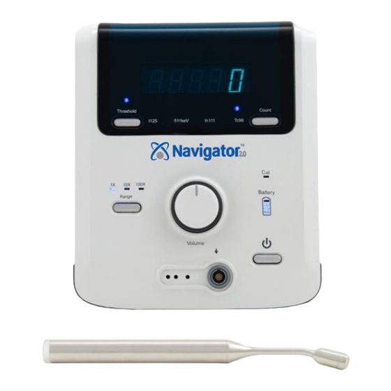
Navigator 2.0 User Manual & Service Guide 2. System Overview and Components Control Unit Battery Navigator 2.0 Control Unit 2-bay Battery Charger and Line Cord Wireless Pilot Probe Battery 14 mm Wireless Pilot Probe 14 mm Standard Sentinel Node Mapping Probe Table 2A. -
Page 14: Precautions
When optional system components are used with the system, maintain probe and patient electrical isolation from earth ground. The optional components include the Co-Pilot™ Device, the probe drape, the Top Gun™ Collimator, and Navigator 2.0 cart. · In the operating room, use the charger at a distance of six feet or greater from the patient. The charger has a rating in the United States of a “patient proximity charger.”... -
Page 15: Control Unit, Battery, Cables, And Co-Pilot
Navigator 2.0 User Manual & Service Guide 4. Control Unit, Battery, Cables, and Co-Pilot 4A-1. Control Unit Features: Front Count Display 10-second Count Button and Indicator Threshold Control Tc99 Indicator Calibration –Check Mode Indicator Range Button and Battery Charge Indicators... - Page 16 Navigator 2.0 User Manual & Service Guide Table 4A-1. Controls and Displays on the Front of the Control Unit Control Display Description Power button: Turns power on and off. Volume knob: Increases/decreases the volume of the audible signal. Display Screen: When turned on, displays the photon count per second.
- Page 17 Navigator 2.0 User Manual & Service Guide Control Display Description Count: Initiates a 10-second photon count. When Count has been pressed, the count indicator on the display screen is illuminated and the display screen will show increasing counts. Probe must be held in a fixed position for entire duration of 10-second count.
-
Page 18: 2. Control Unit Features: Back
Navigator 2.0 User Manual & Service Guide 4A-2. Control Unit Features: Back Integrated Handle Scan/Cal-check Control Fuse Holder Pole Mount Connection Battery Compartment Door 141-00002-001 Rev 3 Revised 10/16/2018... -
Page 19: Battery (Part # N2-8500-00)
Navigator 2.0 User Manual & Service Guide Table 4A-2. Controls and Displays on the Back of the Control Unit Control Display Description For CABLED PROBES only. The SCAN position is the only correct position when a probe is being used during a procedure. When set to SCAN, the CAL indicator on the front of the control unit will not illuminate. - Page 20 While there is a calibration button for each bay, calibration is not necessary for use with the Navigator 2.0. If calibration button is inadvertently pressed, either a flashing blue or solid blue light will illuminate. Simply remove battery and reinsert in order to resume charge.
-
Page 21: Optional Co-Pilot™ Device (Part # Gp-6801-00)
Navigator 2.0 User Manual & Service Guide CAUTION: Do not expose the charger or power supply to water or liquids; the case is not sealed. Do not open the charger or power supply case; no user-serviceable parts are inside. Do not cover the fan exhaust or obstruct the airflow; this will cause overheating. - Page 22 Navigator 2.0 User Manual & Service Guide R Button (Range) C Button (Count) The “C” button is the COUNT Button. Obtain a one-second count by pushing and releasing this button once. Obtain a ten-second count by pushing this button twice, in quick succession. Each time, total counts are shown in the display screen on the control unit.
-
Page 23: Useful Adjustments That Can Be Made During Procedures
Navigator 2.0 User Manual & Service Guide 4E. Useful Adjustments That Can Be Made During Procedures 10-second Count Button and Indicator Threshold Control Range Button and Indicators Power Button Volume Knob Table 4D-1. Useful Adjustments Adjustment Benefit Threshold For Cabled Probes only, this feature increases specificity when only a low number of events are observed. -
Page 24: Cleaning And Disinfection Of Navigator Probes And Cables
· Radioactive Decontamination Procedure – OPTIONAL (see section 5C). CAUTION: All Dilon probes and probe cables must be used inside a sterile drape. The control unit, gain module (if used), and battery/charger are used outside of the sterile field. Probes and probe cables should be cleaned and disinfected separately from the other components. - Page 25 Navigator 2.0 User Manual & Service Guide 141-00002-001 Rev 3 Revised 10/16/2018...
-
Page 26: Radioactive Decontamination Procedure - Optional
Navigator 2.0 User Manual & Service Guide 5B. Radioactive Decontamination Procedure – OPTIONAL An increase in background counts may signal radioactive contamination of the probe or the environment. If a process of elimination shows the probe to be contaminated with radioactive material, the probe must be decontaminated. -
Page 27: Probe Connectivity And Use
Insert a probe battery into the Pilot Probe as follows: 1. Hold probe firm; turn battery cap counterclockwise and remove from probe. Inspect O-ring integrity. If O-ring is missing or damaged, use new battery cap. Contact Dilon Technologies or your distributor for battery cap reorder information. - Page 28 Navigator 2.0 User Manual & Service Guide 2. Install 3V CR 2 lithium battery in Pilot Probe battery holder with positive (+) end facing toward the base of the probe and negative (-) end toward the middle of the probe. Incorrect placement of battery into battery holder for extended periods of time will cause battery to drain quickly.
- Page 29 For Technetium-99m (Tc99), the control unit settings are given in the following table. NOTE: Follow the instructions in the section on ‘Cleaning and Disinfection of Probe’ (Section 5). Table 6A-2. Navigator 2.0 with Wireless Pilot Probe – Settings & Indicators (just prior to surgery) Control / Indicator Setting...
-
Page 30: Troubleshooting
7. Troubleshooting With the exception of the Wireless Pilot Probe’s battery holder, no serviceable components are located inside the control unit or probes. Contact your representative or Dilon Technologies for additional assistance if more detail is required. Table 8A-1. Control Unit Only – Settings and Indicators... - Page 31 Navigator 2.0 User Manual & Service Guide Problem Possible Causes Remedies 2. LED on Pilot Probe Probe battery is dead or Replace with new battery. does not illuminate. installed incorrectly. Verify that battery was inserted correctly into probe (‘+’ should face toward base of probe).
-
Page 32: Specifications
Navigator 2.0 User Manual & Service Guide 8. Specifications 9A. Navigator 2.0 System Specifications The Navigator 2.0 system consists of the control unit, one or more probes, and the system accessories. Table 9A-1. Navigator 2.0 System Specifications Item Description Control Unit Power Source... -
Page 33: Navigator 2.0 System Lifetime
Length: 2.4 m (8ft). Hospital Grade. Navigator 2 and Wireless probe Operating frequency range: 2405-2480 Mhz. 9B. Navigator 2.0 System Lifetime The lifetime of the Navigator 2.0 Control Unit and family of probes is 10 years. 141-00002-001 Rev 3 Revised 10/16/2018... -
Page 34: Support Items
Navigator 2.0 User Manual & Service Guide 9. Support Items The Navigator 2.0 control unit is typically supplied with a complete system. Support items may be purchased from the local Dilon Technologies Navigator representative. At time of publication of this manual, the primary support items have the following part numbers. -
Page 35: Maintenance
10. Maintenance 11A. Overview While the Navigator 2.0 System is virtually maintenance-free, the user should follow a number of steps to ensure proper performance prior to each use. Check each system component for any visible signs of abuse, neglect, or wear, before each use and storage. - Page 36 Navigator 2.0 User Manual & Service Guide The Verification of Standard Gain uses 122 keV energy photons produced by the Isotope of Cobalt-57, to create a known signal in the probe. The control unit expects these detected photons to be in an energy window corresponding to the CENTERED (>0<) position of the test.
-
Page 37: Fuse Replacement Procedure
Navigator 2.0 User Manual & Service Guide 11C. Fuse Replacement Procedure The fuse is to be replaced when necessary by the user (when the fuse is "blown"). The Navigator 2.0 fuse is to be replaced as follows: 1. Push-in and twist the fuse holder cap counter-clockwise. - Page 38 Please contact Dilon Technologies for additional service. An RMA number is required upon return for service. If the device cannot be repaired and or it is determined that its useful life is at an end, contact Dilon Technologies for proper disposal of the unit.
- Page 39 Navigator 2.0 User Manual & Service Guide 12. Recycling At the end of the device life and/or accessories, please send the device and/or its accessories back to Dilon Technologies Authorize Representative in Europe. Ensure the cleaning of the device and/or it accessories before shipment.
- Page 40 Dilon will repair or replace, at its option and without charge, any of the above products which are returned to Dilon or its designated repair site, within the applicable warranty period, with prepayment of shipping costs, and which are determined by Dilon to be defective in materials or workmanship.
Need help?
Do you have a question about the Navigator 2.0 and is the answer not in the manual?
Questions and answers