
Related Manuals for KMT Streamline SL-IV


Summary of Contents for KMT Streamline SL-IV
- Page 1 STREAMLINE HIGH PRESSURE WATERJET PUMP OPERATION and SERVICE MANUAL SL-IV 15hp HSEC 208/230 Manual No. 05139142 Printed: 12/09/03 05139134.doc...
- Page 2 KMT Waterjet Systems believes the information described in this manual to be accurate and reliable. Much care has been taken in its preparation, however, the Company cannot accept any responsibility, financial or otherwise, for any consequences arising out of the use of this material.
-
Page 3: Table Of Contents
TABLE of CONTENTS SECTION 1 INTRODUCTION SL-IV 11kW (15 hp) Waterjet Pump General Information Physical Description 1.1.1 Standard Equipment Functional Description 1.2.1 Functional Features Worldwide Product Support 1.3.1 Service Department 1.3.2 Spare Parts 1.3.3 Questionnaire Safety 1.4.1 Labels and Abbreviations 1.4.2 Safety Procedures 1.4.3... - Page 4 TABLE OF CONTENTS Scheduled Maintenance General Maintenance SECTION 5 TROUBLESHOOTING Troubleshooting SECTION 6 LOW PRESSURE WATER SYSTEM Features Oil Cooling Water Supply Cutting Water Supply 6.2.1 Normal Operating Condition 6.2.2 Operation 6.2.4 Low Pressure System Protection Maintenance Overview 6.3.1 Water Filter Service SECTION 7 HIGH PRESSURE WATER SYSTEM High Pressure (HP) Water Components...
- Page 5 TABLE OF CONTENTS Motor/ Hydraulic Service Maintenance 9.3.1 Pump Compensator Adjustment 9.3.2 Pump /Motor Coupling Service Pump Service 9.4.1 Pump Case Prefill 9.4.2 Seal Kits SECTION 10 RECIRCULATION SYSTEM Features 10-1 10.1 Components 10-1 10.2 Operation 10-1 10.3 System Pressure Protection 10-2 10.4 Maintenance Overview...
-
Page 6: Section 1 Introduction Sl-Iv 11Kw (15 Hp) Waterjet Pump General Information
Section 1 INTRODUCTION SL-IV 11 kW (15 hp) Waterjet Pump General Information The Streamline SL-IV 11 kW (15 hp) Waterjet Pump, maintains the level of component reliability and ease of installation and maintenance that have made the KMT Waterjet Streamline waterjet pumps the standard of the industry for both water and Hydrobrasive™... - Page 7 SECTION 1 INTRODUCTION Dimension Letter inch 5.50 8.00 10.50 16.50 15.75 19.00 21.82 1.31 32.78 1422 56.00 28.00 July 2003 05130661...
-
Page 8: Standard Equipment
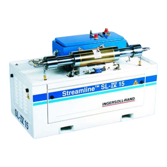
SECTION 1 INTRODUCTION The SL-IV11kW (15hp) Waterjet pump is enclosed in a frame with the dimensions of 56” length, 28” width, and 32.8” height. The high pressure system is conveniently mounted on a drip pan. All service components are easily accessible from at least two sides simplifying maintenance. The entire high pressure system can be removed from the rest of the unit quickly for maintenance and serviceability. -
Page 9: Functional Description
SECTION 1 INTRODUCTION Functional Description The SL-IV 11 kW (15 hp) Waterjet Pump meets the automotive and industrial markets needs of low to high volume production of water jet pumps. The maximum HP water pressure is limited by a hydraulic relief valve that is certified and sealed by TUV. -
Page 10: Worldwide Product Support
Phone: 49–(0)6032–997–117 Fax: (620) 856–5050 Fax: 49–(0)6032–997–270 1.3.2 Spare Parts KMT Waterjet maintains a well stocked Spare Parts Department staffed by well trained knowledgeable personnel. Emergency shipment is available. Contact the Service Department of KMT Waterjet Systems. 1.3.3 Questionnaire The following equipment and service manual questionnaire will provide information to allow us to serve you better. - Page 11 SECTION 1 INTRODUCTION EQUIPMENT AND SERVICE MANUAL QUESTIONNAIRE We have just installed a new SL-IV 11 (15 hp) Waterjet Pump at your location. We are interested in your initial impressions of the unit and its installation. Please take a few moments and answer the following questions. General Appearance Was unit received in good condition? Comments:...
- Page 12 SECTION 1 INTRODUCTION Manual Organization 1. Does the table of contents help you find topics easily? Comments: 2. Is the information well organized? Comments: 3. Is the page layout suitable for the material being presented? Comments: Graphics 1. How do you rate the quality and quantity of the photos/illustrations? Comments: Text 1.
-
Page 13: Safety
SECTION 1 INTRODUCTION Safety Safety procedures and safe practices must be followed during installation, operation, and maintenance of the waterjet pump. In this section we have provided label and sign descriptions used in this manual, as well as recommended safety procedures. 1.4.1 Labels and Abbreviations The following describes hazard classifications of the waterjet pump. - Page 14 SECTION 1 INTRODUCTION Rear of Waterjet Pump HP Water "OUT" Plant Air "IN" Cooling Water "IN" Cooling Water "OUT " Cutting Water "IN" Drain The following figure shows other safety labels or icons used on the SL-IV waterjet pump. Trapped HP water or oil warning warns against the hazard of trapped HP water or hydraulic pressure after the pump has been shut off.
-
Page 15: Safety Procedures
SECTION 1 INTRODUCTION WARNING Pumping System can remain pressurised when pump is not operating. Can cause injury or death. Disconnect pump power source and depressurise system before servicing Figure 1-1. Other Safety Labels & Icons Used on the SL-IV Waterjet Pump (a) Trapped HP Water or (b) Electrical Shock Hazard (c) Hot Surface Warning... - Page 16 SECTION 1 INTRODUCTION • All high pressure leaks must be repaired immediately. • Inspect all equipment on a scheduled basis. • Before performing any maintenance on the unit, MECHANICALLY LOCK THE MAIN CONTROL POWER OFF, and assure the high pressure has been bled off. Never do any work on the unit without making sure the electrical panel disconnect is locked out with a padlock WARNING...
-
Page 17: High Pressure (Hp) Piping Safety
SECTION 1 INTRODUCTION 1.4.3 High Pressure (HP) Piping Safety High pressure piping must be installed without torsional or bending stresses. Proper supports and guides must be provided. 9/16” outside diameter HP tubing and fittings are recommended between the pump and the cutting station. This large tubing size will reduce vibration, strain and motion between the pump piping and the cutting area. -
Page 18: Emergency Medical Treatment
SECTION 1 INTRODUCTION 1.4.4 Emergency Medical Treatment An information card to aid treating a waterjet injury is included in the binder of each manual. The card is shown below. Contact the address shown for additional cards. Medical Alert “This person has been working with water jetting at pressures to 55,000 psi (374MPa, 3740 bar, 3867 Kg/cm ) with a jet velocity of 3,000 fps (914 mps). -
Page 19: Section 2 Installation
Provide, install and connect wiring between the intensifier pumps, and the cutting station control system. • KMT Waterjet supplies a pre-filled hydraulic system. If fluid is low or empty due to leakage during transit, the system must be filled per specifications. July 2003... -
Page 20: Seller Obligations
SECTION 2 INSTALLATION 2.1.2 Seller Obligations If KMT Waterjet is requested, the following tasks will be the responsibility of the KMT Waterjet technician at installation. • Insure site preparation is satisfactory. • Remove internal strapping and blocking material. • Insure that power is connected prior to equipment turn on. -
Page 21: Service Connections
SECTION 2 INSTALLATION Control Wiring: Wiring for remote control of the pump must be in accordance with national and local electrical codes. The SL-IV Waterjet Pump has a 24vdc electrical control system and has provisions for remote operation in the pump control panel. - Page 22 SECTION 2 INSTALLATION Cutting water released in the pump is discharged from the drain port and must be piped to an appropriate location (i.e. sewer line). Piping must meet national and local piping codes. Compressed Air: The facility air connection to the SL-IV Pump should provide clean, dry air at 5.9 bar (85 psig).
-
Page 23: Tools And Equipment
SECTION 2 INSTALLATION 2.2.3 Tools and Equipment 2.2.3.1 HP Tube Coning and Threading Procedures Determine Tube Length - Measure, the distance (L), between the fittings, then add two times the tube engagement length in the following table. Cut tubing to length and deburr. - Page 24 SECTION 2 INSTALLATION Cone and Thread Tube Cone and thread both ends of the tube per following diagram and procedure. Cone and Thread Dimensions O.D. Size I.D. size D (max) L (max) Thread mm (inch) mm (inch) mm (inch) mm (inch) NF-LH 6.35 (1/4") 2.11 (0.083)
- Page 25 SECTION 2 INSTALLATION To cone the tubing, use the following figure as reference. Cone and Threading Tool Item Description (1) Cutter Handle (2) Cutter Support (3) Feed Nut (4) Cutting Blades (5) Collet (6) Housing (7) Gland Nut Tube Size (inch) 1/4”...
- Page 26 SECTION 2 INSTALLATION Coning • Place appropriate size coning tool in vise so that lubricant can flow to cutting blades (4). • Set feed nut (3) location as shown in dimension A. • Slide tubing through collet (5) until end contacts cutting blades (4) and tighten gland nut (7) just enough to slightly grip tubing.
- Page 27 SECTION 2 INSTALLATION HP Tube End Connection - Regular The following type of connection is for general applications, where the only load on tubing is due to internal pressure. 1. Slip gland nut (2) on tubing (1) as shown and lubricate thread with High Purity Goop.
- Page 28 SECTION 2 INSTALLATION HP Tube End Connection - Antivibration The following type of connection must be used when tubing is subjected to vibration, rotation, movement, and side loads (i.e. whip tubing). Lubricate threads as above. Do not depend on end connection to take the tubing load alone.
-
Page 29: Section 3 Operation
SECTION 3 OPERATION Section 3 OPERATION Features The SL-IV 11 kW (15hp) Waterjet Pump is composed of the following systems: • Low Pressure Water System • High Pressure Water System • Hydraulic System • Recirculation System • Electrical System 3.1 Operation Overview The I-R SL-IV Waterjet Pump can be started and stopped from either the pump- mounted controls or from (optional) remote controls located at or near the cutting system operator’s console. -
Page 30: Operator Console
SECTION 3 OPERATION 3.2 Operator Console Operator interface with the SL-IV Waterjet Pump is through the operator’s panel. The panel consists of the emergency stop (E-Stop) palm button START, STOP, control power RESET pushbuttons, and indicator lights. All electrical power to the SL-IV pump passes through the main disconnect, controlled by the panel disconnect handle on the enclosure. - Page 31 SECTION 3 OPERATION Item Description 1 Palmbutton – Emergency Stop 2 Handle – Electrical Disconnect 3 Pushbutton – (Control Power On—White Light) 4 Selector Switch-Local/Remote Control 5 Pushbutton – (Stop Pump/ Fault--Red Light) 6 Pushbutton – (Start Pump--Green Light) 7 Hourmeter 8 Decal—Shock Hazard p 3-3 05132519...
-
Page 32: Operating Procedures
SECTION 3 OPERATION 3.2.2 Operating Procedures The lights on the operator’s console provide information. The following pages show start, stop and fault recovery procedures. START PROCEDURE 1. Pull EMERGENCY STOP (E-STOP) palmbutton. 2. Push CONTROL POWER ON button. CONTROL POWER ON button light (WHITE) will be ON. -
Page 33: Special Start-Up Procedures
SECTION 3 OPERATION 3.3 Special Start-Up Procedures 3.3.1 Startup Following HP Maintenance The following procedure should be used after intensifier HP component maintenance. Failure to expel air from High Pressure (HP) internal passages following CAUTION intensifier maintenance will cause damage to HP seals. 1. - Page 34 SECTION 3 OPERATION Item Description Electric Motor Hydraulic Gear HP Attenuator Hydraulic Pump Pump Intensifier Manifold Heat Exchanger 15 LP water Filter Solenoid Shutoff Directional Control Oil Filter Valve Valve 17 Hydraulic Reservoir • Insure all cooling water valves, supply water valves, and high pressure valves are open.
-
Page 35: Pump Operation
SECTION 3 OPERATION To Check Motor Direction 1. Remove front cover from the SL-IV Pump to: 1) locate pressure gage on the hydraulic pump outlet port, and 2) view the motor fan. Two methods for checking motor rotation are possible: 1) one person watches motor fan while a second person “jogs”... - Page 36 SECTION 3 OPERATION Item Description 1 Palmbutton – Emergency Stop 2 Handle – Electrical Disconnect 3 Pushbutton – (Control Power On—White Light) 4 Selector Switch-Local/Remote Control 5 Pushbutton – (Stop Pump/ Fault--Red Light) 6 Pushbutton – (Start Pump--Green Light) 7 Hourmeter 8 Decal—Shock Hazard Pull out EMERGENCY STOP (E-STOP) palm button.
- Page 37 SECTION 3 OPERATION to 4,600 bar (68,000 psi) by the tamper- resistant main hydraulic relief valve. (refer to procedure 3.3.4) To assure proper oil viscosity and lubrication of the CAUTION hydraulic system, always operate the unit at a hydraulic oil pressure of less than 70 bar (1,000 psi) until the oil temperature is at least 30°C (86°F).
-
Page 38: Hydraulic Pump Pressure Compensator Adjustment Procedure
SECTION 3 OPERATION Piston Pump Cap Nut Compensator Jam Nut Allen Wrench (3mm) Adjustment Screw Outer Adjustment Screw 3.3.4 Hydraulic Pump Pressure Compensator Adjustment Procedure Locate hydraulic pump compensator adjustment screw Note that main adjustment screw is INBOARD, while outboard adjustment screw is used for pump internal case drain pressure. -
Page 39: Shutdown Procedure
SECTION 3 OPERATION Note that the difference between HP water pressure with the nozzle(s) open and closed should be less than approximately 200 bar (2,900 psi). If the pressure difference exceeds 200 bar, then look for excessive line loss or possible blockage, such as a clogged HP water filter element. - Page 40 SECTION 3 OPERATION 2. To correct the condition do the following: • Fill to proper level • Observe all safety procedures • Check for cause of low level, leaks, etc. • Make required repairs 3. After problem is corrected the following occurs: •...
-
Page 41: Maintenance
SECTION 4 MAINTENANCE Section 4 MAINTENANCE Maintenance This section provides an overview of “Scheduled Maintenance” and “Preventive Maintenance”. In addition, maintenance of the five systems is necessary and is described in their respective sections. Refer to the following sections for detailed information on the operator console and systems maintenance: •... - Page 42 SECTION 4 MAINTENANCE Item Description (1) Hydraulic Pump (2) Recirculation Pump (3) Intensifier Assembly (4) Control Panel (5) HP Attenuator July 2003 p. 4-2 05130679...
-
Page 43: Scheduled Maintenance
SECTION 4 MAINTENANCE Scheduled Maintenance Check Item to be Checked Major Component Description Oil Level Hydraulic Oil Tank Oil Sample Hydraulic System Fluid Level & Hydraulic Cartridge Hydraulic Cylinder Leak Checks Seals Plunger Seals HP Cylinder Sealing Head HP Cylinder Low Pressure Filter Water Supply Pressure Assembly... - Page 44 When blowing off parts with compressed air, use only clean, dry air. When flushing parts with a solvent, use only clean, filtered fluid. • Always use original KMT Waterjet replacement parts, for consistent performance, reliability, safety, and to protect equipment warranty. Safety Recommendations •...
- Page 45 Check all high pressure connections for leaks. Unusual requirements should be referred to the Technical Services group at KMT Waterjet. To contact the KMT Waterjet Spare Parts Department: USA: Parts Department Europe: Spare Parts Manager KMT Waterjet Systems...
-
Page 46: Section 5 Troubleshooting
SECTION 5 TROUBLESHOOTING Section 5 TROUBLESHOOTING SL-IV Pump Will Not Start Condition & Possible Causes Corrective Action E-STOP Button Depressed Pull out E-STOP button. Push CONTROL POWER ON button – white light on CONTROL POWER ON button should illuminate. Power Disconnected Check that main power is present. - Page 47 SECTION 5 TROUBLESHOOTING Red Flashing Light, Message On Operator’s Console Condition and Possible Causes Corrective Action LEAK Check for HP piping leaks. Check for HP seal leak. Check for HP check valve leak. Check for HP valve leak. Check for HP pump leak. Check for sufficient water supply.
- Page 48 SECTION 5 TROUBLESHOOTING Oil or Water Leaks from HP Cylinder Weep Holes Condition and Possible Causes Corrective Action Plunger Oil Seal Leak Check hydraulic cylinder O-ring leakage. Check proximity switch area for oil leakage. Remove, inspect, replace or clean hydraulic seal (cartridge).
- Page 49 SECTION 5 TROUBLESHOOTING HP Check Valves Leak 1. Disconnect the proximity switch cable of either HP cylinder. If there are no visible HP water 2. With the cutting nozzle valve open, start leaks, but there are higher pump at low pressure; the piston will move temperatures on HP cylinder or and stop at the opposite HP cylinder.
-
Page 50: Section 6 Low Pressure Water System
SECTION 6 LOW PRESSURE WATER Section 6 LOW PRESSURE WATER SYSTEM Features The SL-IV Waterjet Pump is equipped with two low pressure circuits: • Cutting water supply for HP intensifier assembly. • Cooling water supply for the oil-to-water heat exchanger. The low pressure water system supplies the pump with the following: •... -
Page 51: Cutting Water Supply
SECTION 6 LOW PRESSURE WATER inlet temperature is required to maintain oil temperature under extreme operating conditions. Cooling water flow rate is regulated by the water modulating valve (19). A thermal bulb (20) mounted in the hydraulic reservoir varies cooling water flow rate relative to hydraulic oil temperature. -
Page 52: Low Pressure System Protection
SECTION 6 LOW PRESSURE WATER The water filter assembly includes a small bleed valve that is useful in performing maintenance on the filter. Prior to removing the filter bowl the bleed valve provides a convenient means of releasing any pressure trapped inside the filter. -
Page 53: Section 7 High Pressure Water System
SECTION 7 HIGH PRESSURE WATER Section 7. HIGH PRESSURE WATER SYSTEM – SL-IV 15hp High Pressure (HP) Water The high pressure (HP) water system takes the relatively low pressure water inlet to up to 3,800 bar (55,000 psi) supplying orifice diameters appropriate to the waterjet pump’s operating power (See Specifications, Section 11). -
Page 54: Intensifier Disassembly And Reassembly
SECTION 7 HIGH PRESSURE WATER Intensifier Disassembly and Reassembly Detailed instructions are provided on disassembly and reassembly of the hydraulic intensifier, including HP seal maintenance. A discussion of detailed inspection and repair for individual HP subassemblies is also provided. The HP attenuator is discussed but no disassembly procedures are included since attenuators are not serviceable by the customer. -
Page 55: Hp & Lp Water Piping
SECTION 7 HIGH PRESSURE WATER 7.2.1 HP & LP Water Piping Disconnect from/Reconnect to Waterjet Pump Before performing maintenance on the waterjet pump WARNING observe electrical LOCK OUT/TAG OUT procedures. With 13/16” open wrench loosen and remove HP Piping attached to discharge HP check valve. -
Page 56: Hp Sealing Head
SECTION 7 HIGH PRESSURE WATER 7.2.2 HP Sealing Head--Remove from/Install in Waterjet Pump Remove low pressure and HP piping from sealing head using procedure in Section 7.2.1. With pin spanner wrench located on head nut to turn counterclockwise, and cylinder wrench installed on cylinder to hold in opposite direction of rotation;... - Page 57 SECTION 7 HIGH PRESSURE WATER Remove the sealing head. Using the seal removal tool, remove the HP seal components remaining in the HP cylinder outboard end. Remove the cylinder bore liner. The HP cylinder can now be removed for further tear down, or the sealing head and HP seal can be serviced.
-
Page 58: Hp Cylinder
SECTION 7 HIGH PRESSURE WATER 7.2.3 HP Cylinder Remove from/Install in Waterjet Pump The HP cylinder can be unthreaded from the cylinder head either with or without its head nut and sealing head assembled to it. We recommend the following procedure since the combined parts make up a rather heavy assembly that is difficult to handle. - Page 59 SECTION 7 HIGH PRESSURE WATER • J-shaped seal body and O-ring against U-shaped seal body. The open side of the J-seal should face outboard (toward the sealing head). Inspect the HP cylinder threads and apply High Purity Goop to the threads and shoulder guides, then screw the HP cylinder into the hydraulic cylinder head.
-
Page 60: Hydraulic Seal Cartridge & Plunger
SECTION 7 HIGH PRESSURE WATER 7.2.4 Hydraulic Seal Cartridge & Plunger -- Remove/Install With the HP cylinder removed from the hydraulic cylinder head (Section 7.2.3), the following items become accessible: • Cartridge retainer flange • Hydraulic seal cartridge • Plunger •... - Page 61 SECTION 7 HIGH PRESSURE WATER Using cartridge/plunger removal tool threaded to the seal cartridge, pull the cartridge outward over the plunger. Seals in the hydraulic cartridge can be removed and replaced, or the entire cartridge can be replaced. It is recommended that at least one spare cartridge be kept on hand, ready to install.
-
Page 62: Hydraulic Cylinder Head & Hydraulic Piston
SECTION 7 HIGH PRESSURE WATER 7.2.5 Hydraulic Cylinder Head and Hydraulic Piston Disassembly 1. Remove sealing head and HP cylinder using procedures in Sections 7.2.2 and 7.2.3. 2. Remove proximity switch (19) at cylinder end to be serviced. If both cylinder heads and/or the hydraulic piston (21) are to be removed, both proximity switches must be removed. - Page 63 SECTION 7 HIGH PRESSURE WATER Item Description (2) Plunger (4) Cylinder Head (8) Hyd Cartridge, Plunger Seal Assy (9) Bushing Retainer Flange (14) Retaining Ring (15) Hydraulic Cylinder (16) O-ring (17) Backup Ring (18) Cap Screw (19) Proximity Switch (20) Cap Screw (21) Hyd Piston Assy (23) Manifold (25) Cap Screw...
- Page 64 SECTION 7 HIGH PRESSURE WATER Intensifier Subassemblies Inspection and Repair The inspection and repair of the following subassemblies will be discussed: • Discharge HP Check Valve, Section 7.3.1 • Inlet Check Valve, Section 7.3.2 • Sealing Head, Section 7.3.3 • HP Cylinder, Section 7.3.4 •...
-
Page 65: Discharge Hp Check Valve
SECTION 7 HIGH PRESSURE WATER 7.3.1 Discharge HP Check Valve The HP discharge check valve can be serviced with the sealing head either installed in or removed from its intensifier HP cylinder. 1. Remove the gland nut from the sealing head using two 30mm (1- 3/16”) wrenches. - Page 66 SECTION 7 HIGH PRESSURE WATER 3. Inspect the poppet, spring, and guide for wear. Replace the spring and guide if worn. 4. Apply a thin film of High Purity Goop to the sealing face of the gland nut. Install the guide, spring, and poppet into the gland nut. Apply a coating of food grade grease to the check poppet to hold it in place when installing gland nut in sealing head.
-
Page 67: Inlet Check Valve
SECTION 7 HIGH PRESSURE WATER 7.3.2 Inlet Check Valve Use a ½” flat bladed screwdriver to unscrew the poppet retainer from the sealing head. The inlet check valve is disassembled. Inspect and refinish the sealing head face seal surface per instructions in Section 7.3.3. -
Page 68: Sealing Head
15 degrees every stroke. Be careful not to tilt or tip the head while polishing it as to not scrape the part. When the sealing head is flat and smooth, perform a final polish with 600 grit wet/dry sandpaper. A mirror finish is required. KMT Waterjet offers a refinishing service. Nov 2002 05126826 p. -
Page 69: Hp Cylinder
SECTION 7 HIGH PRESSURE WATER 7.3.4 HP Cylinder At a workbench, use the seal removal tool to prevent scratching the cylinder bore sealing surface. Use a pulling action to remove the sealing head HP seal. Remove the bore liner. Use a plastic-faced hammer and the seal removal tool to drive out the plunger HP seal and follower. -
Page 70: Plunger
If any of these conditions become severe, the plunger HP seal and possibly the hydraulic seals will leak excessively. Repair of plunger surface flaws usually cannot be accomplished on site. KMT Waterjet offers a plunger reconditioning service. Item Description... -
Page 71: Hydraulic Seal Cartridge
SECTION 7 HIGH PRESSURE WATER 7.3.6 Hydraulic Seal Cartridge Carefully remove worn seals and O-rings from cartridge by pushing them with a dowel or similar object. Remove seals positioned close to the open ends first, working toward the interior. Examine seals for unusual wear, deformation or cuts. - Page 72 SECTION 7 HIGH PRESSURE WATER During seal installation, orient U-cup packing seals (2) (8) so that they match figure above. Apply food grade grease to seals and cartridge seal components to aid in installation and seal seating. Use installation tool, if available, for installation of U-cup seals (2) (8).
-
Page 73: Hydraulic Piston
SECTION 7 HIGH PRESSURE WATER 7.3.7 Hydraulic Piston The hydraulic piston contains a seal assembly, bearing rings, pins and flat spring bands, and check valves. Bearing rings (10) provide wear contact between piston and cylinder ID. Plungers (12) are held in place by 6 each pins (2) per plunger. - Page 74 SECTION 7 HIGH PRESSURE WATER 2. With seal and bearings removed, inspect seal groove bottom for marks or scratches and residue buildup. Clean and /or repair groove surfaces as required. 3. Install replacement bearing rings (10). 4. Install replacement piston seal assembly (9). First install inner ring, taking care that this ring is not twisted after installation.
- Page 75 SECTION 7 HIGH PRESSURE WATER thread retainer (3) over check valve cartridge (4). Allow 24 hours for thread locking compound to set. 3. Install plugs (11) in cross- drilled passages by applying thread locking compound to plug threads. Then thread plugs (2 each per hole), with the second plug acting to lock in the first.
- Page 76 SECTION 7 HIGH PRESSURE WATER (15) Hydraulic Cylinder (19) Proximity Switch (20) Seal Ring Compression Tool (P460) (21)Hydraulic Piston Assy Nov 2002 05126826 p. 7-24...
-
Page 77: Hydraulic Cylinder
SECTION 7 HIGH PRESSURE WATER 7.3.8 Hydraulic Cylinder The inside diameter surface of the hydraulic cylinder should be inspected for wear grooves and surface finish whenever the hydraulic cylinder heads are removed. Excessive grooving on this bore is indicative of piston seal wear. -
Page 78: Hp Dump Valve
HP Attenuator There is no servicing of the HP attenuator at the customer level. The seals in the HP attenuator are tested at KMT Waterjet to high pressure in excess of operating pressure making disassembly difficult. In the event of a HP water leak of a HP attenuator, the attenuator should be replaced. -
Page 79: Section 8 Electrical System
SECTION 8 ELECTRICAL SYSTEM Section 8 ELECTRICAL SYSTEM Features The electrical system contains all functions necessary for turnkey operation. This includes the control and starter panel, intensifier reversal circuit. The electrical enclosure, buttons, lights, and electrical harnesses into and out of this enclosure can be exposed to occasional water spray and dust per NEMA-12 standards. -
Page 80: Operation
SECTION 8 ELECTRICAL SYSTEM 8.1.3 Operation During normal operation, the control panel shows operating messages and the RUN green light will be lit. After pulling the EMERGENCY STOP and CONTROL POWER ON pushbutton is pressed: MOTOR STARTER/ INTENSIFIER CONTROL PANEL, SL-IV/15hp Item Item Description Item... -
Page 81: Maintenance Overview
SECTION 8 ELECTRICAL SYSTEM After pressing the START Pushbutton: • The unloading valve delays hydraulic pressure build-up while the motor starter circuit accelerates the motor to normal rotating speed. • The intensifier assembly starts operating. Reversal position is sensed by proximity switches, which send signals to the relay logic inside the control panel. - Page 82 SECTION 8 ELECTRICAL SYSTEM Replace Proximity Switch 1. Turn off waterjet pump, disconnect and LOCKOUT electric power. 2. Disconnect cable. 3. Unscrew bolts, remove proximity switch. 4. Install new switch. Install bolts. 5. Torque bolts to 16-18 Nm (140-160 in-lbs.). July 2003 p.
-
Page 83: Section 9 Hydraulic System
SECTION 9 HYDRAULIC SYSTEM Section 9 HYDRAULIC SYSTEM Hydraulic System The hydraulic system drives the water intensifier assembly to produce a HP waterjet cutting stream. The hydraulic system is composed of a variable- displacement; pressure- compensated axial piston pump, driven by an electric motor. -
Page 84: Components
SECTION 9 HYDRAULIC SYSTEM • Pressure adjustment control – allows for infinite pressure settings though out the entire pressure range for flexibility. 9.1.2 Components Following are the hydraulic system components: NOTE The main pump is direct-mounted to the motor. The main pump pressure control is adjusted at the pump compensator. -
Page 85: Operation
SECTION 9 HYDRAULIC SYSTEM Operation The hydraulic system operates at its adjusted pressure setting up to the maximum flow capacity of the variable displacement piston pump. During motor start the piston pump flow is ported to reservoir to reduce load on the motor. The electric motor (1) drives the piston pump (2) and gear pump (3). -
Page 86: Motor Startup
SECTION 9 HYDRAULIC SYSTEM 9.2.3 Motor Startup The electric motor (1) starts in two stages (Wye-Delta). During the initial (Wye) stage, piston pump (2) pressure is maintained low to reduce torque load on the motor. Piston pump depressurization is accomplished by delayed closing of check valve (9) located in the manifold (25). - Page 87 SECTION 9 HYDRAULIC SYSTEM 2 Piston Pump 32 Cap Nut 22 Compensator 33 Jam Nut 31 Allen Wrench (3mm) 34 Adjustment Screw 35 Outer Adjustment Screw The hydraulic system components that require periodic maintenance are the motor and the pump compensator. The motor needs to be serviced every 5000 hours of use.
-
Page 88: Pump /Motor Coupling Service
SECTION 9 HYDRAULIC SYSTEM 9.3.2 Pump /Motor Coupling Service The main pump is connected to the electric motor by means of a keyed shaft close coupling. If the pump and motor must be separated, then it is necessary to use the special lubricant specified in the parts list. Failure to use the proper lubricant could result in excessive wear of/ damage to the shaft CAUTION... -
Page 89: Section 10 Recirculation System
SECTION 10 RECIRCULATION SYSTEM Section 10 RECIRCULATION SYSTEM Features The recirculation system keeps the hydraulic oil at operating temperature while using the minimum amount of cooling water flow. The system also provides the necessary oil conditioning and filtration to maintain oil cleanliness. The conditioning of the hydraulic oil includes cooling it, cleaning it, and together with the hydraulic reservoir, removing air bubbles entrained in the oil due to agitation and turbulent flow in the main pump circuit. - Page 90 SECTION 10 RECIRCULATION SYSTEM 1 Electric Motor, 15 hp 19 Water Modulating Valve 2 Piston Hydraulic Pump 20 Temperature Sensor Bulb 3 Gear Hydraulic Pump 21 Drain Valve, Reservoir 4 Hydraulic Reservoir 27 Fill Port, Hydraulic Reservoir 5 Hydraulic Filter Housing 37 Filter Element 7 Hydraulic Pressure Gage 38 Bypass, Filter...
-
Page 91: Maintenance Overview
SECTION 10 RECIRCULATION SYSTEM 10.4 Maintenance Overview During normal operating condition, the oil will be maintained at the correct operating temperature. In order to get the best value from the hydraulic system (including the recirculation system) one should change the filter element when it indicates that it is time. - Page 92 SECTION 10 RECIRCULATION SYSTEM Gasket, Hydraulic Reservoir Cover Heat Exchanger Sensor, Oil Temperature and Low Level Well, Temperature Sensor Bulb Breather, Air Drain Valve Sight Gage (with thermometer) Plug Filter Head Adapter, Fill Port Filter Element Elbow Tee Fitting, Fill Port Ref.
- Page 93 SECTION 10 RECIRCULATION SYSTEM The breather is not a fill component, and must not be WARNING used as a fill point. Replace Hydraulic Oil 1. Drain the reservoir, by connecting the inlet hose of the oil filter/ transfer pump to the drain valve. Open valve and pump oil to container. 2.
-
Page 94: Section 11 Specifications
SECTION 11 SPECIFICATIONS SECTION 11 SPECIFICATIONS Specifications Following are the specifications for the SL-IV 11kW(15hp) Waterjet Pump. Included are the specifications for the equipment, torque, cutting water, cooling water, and the maximum quantity of orifices that can be supported. Equipment Specifications 11 (15) kW (hp) SL-IV Waterjet Pump Size... - Page 95 SECTION 11 SPECIFICATIONS 11(15) kW (hp) SL-IV Waterjet Pump Size Optimum temperature 46(115) °C(°F) °C(°F) Hot oil shutdown 62(144) Beta 10 >/= Fluid Filtration Rating Note [6] Fluid Cleanliness Level 17/14 Note [7] -Hydraulic Pump Type Piston Displacement Variable Pressure Compensated Flow rate 38.7(10)
-
Page 96: Torque Specifications
COMPONENTS. Use of an antiseize thread lubricant, like High Purity Goop (P/N 10084440) is highly recommended for tightening of stainless steel HP water fittings. A torque wrench kit is available from KMT Waterjet. (P/N 49895436). Jan 2003 p. 11-3 05130653... -
Page 97: Cutting Water Specifications
SECTION 11 SPECIFICATIONS Cutting Water Specifications The cutting water supply to the waterjet pump must meet the following specifications. High concentration of dissolved solids, especially calcium, silica, and chlorides, will affect high pressure component life. A water analysis will indicate the type of water treatment necessary. -
Page 98: Orifice Support Capacity
SECTION 11 SPECIFICATIONS A positive index indicates a tendency to deposit calcium carbonate, the higher the positive value, the higher the scale formation. A zero index corresponds to water that is in equilibrium with respect to calcium carbonate. Orifice Support Capacity The SL-IV Waterjet Pump supplies high pressure (HP) water up to 3,800 bar (55,000 psi). -
Page 99: Section 12 Parts Lists
SECTION 12 PARTS LISTS PARTS LISTS For: SL-IV 15 hp HSEC High Pressure Waterjet Pump Version 1.0 208/230/480/3φ/50-60 Hz Intensifier To contact the KMT Waterjet Spare Parts Department: Parts Department Europe: Technical Manager KMT Waterjet Systems KMT Waterjet Systems GmbH P.O. Box 231 Wasserstrahl–Schneidetechnik... -
Page 100: Parts Lists
SECTION 12 PARTS LISTS SECTION 12 PARTS LISTS 12.1 General This section contains parts lists for service procedures and part identification, along with electrical and plumbing schematics of the SL-IV 15 hp Waterjet Pump. The reader can use these parts lists to identify the part on a drawing, and then find the part number and part description corresponding to the drawing balloon number. - Page 101 SECTION 12 PARTS LISTS Fig # Figure Title Part Number Page # 12-1 Waterjet Pump Assembly 80080641-480v, 80082365-208v 12-5 12-2 Intensifier Assembly 80079999 12-7 12-3 Seal Head Assembly 80072349 12-9 12-4 Hydraulic Piston 05132253 12-11 12-5 Hydraulic Cartridge 05130091 12-13 12-6 High Pressure Piping 80080153...
- Page 102 SECTION 12 PARTS LISTS Figure 12-1. WATERJET PUMP 80080641-480v, 80082365-208v ITEM No. QTY. PART No. DESCRIPTION 80080153 HP Water Assembly 05140140 Electrical Assembly 05140801 80080179 Bulkhead Pipe Assembly 05126248 Frame Assembly 05126230 Reservoir Assembly 05125919 Motor/Pump Assembly 05130042 Hydraulic Hose Connections 80080633 Decal Package 05072582...
- Page 103 SECTION 12 PARTS LISTS p. 12-5 05139159...
- Page 104 SECTION 12 PARTS LISTS Figure 12-2 HYDRAULIC INTENSIFIER ASSEMBLY 80079999 ITEM No. QTY. PART No. DESCRIPTION 05144647 Body, Cylinder, HP, 1.13-in. ID 05119151 Plunger, Ceramic 80072349 Head Assembly, Sealing 05034772 Head, Cylinder 05149703 Seal Assembly 05144696 Seal Spacer 80073646 Nut, Retaining, Sealing Head 05130091 Seal Assembly, Plunger, Cartridge, Hydraulic 05007786...
- Page 105 SECTION 12 PARTS LISTS p. 12-7 05139159...
- Page 106 SECTION 12 PARTS LISTS Figure 12-3 SEALING HEAD ASSEMBLY 80072349 ITEM No. PART No. DESCRIPTION 49834039 Body, Sealing Head 05144662 Poppet, Inlet, Cutting Water 05116777 Gland, HP, Sealing Head 05112768 Seat, HP, Sealing Head 05116561 Poppet, Valve, HP Check 05144670 Retainer, Poppet 05147863 Spring, Compression...
- Page 107 SECTION 12 PARTS LISTS p. 12-9 05139159...
- Page 108 SECTION 12 PARTS LISTS Figure 12-4 HYDRAULIC PISTON ASSEMBLY 05132253 ITEM No. PART No. DESCRIPTION 05132261 Body, Hydraulic Piston 05074380 Pin, Clevis 05049887 Screw, Set, Socket, with Through Hole 10148757 Valve, Check, Cartridge, with O-ring 49877509 Adhesive, Thread Locker 05088364 Ring, Snap, Flat Wire 05049994 Ring, Backup...
- Page 109 SECTION 12 PARTS LISTS p. 12-11 05139159...
- Page 110 SECTION 12 PARTS LISTS Figure 12-5 HYDRAULIC CARTRIDGE SEAL ASSEMBLY 05130091 ITEM No. PART No. DESCRIPTION 05130109 Body, Seal, Cartridge 05015060 Seal, U-Cup, with O-ring 10193522 O-ring 05050760 Ring, Backup 05129481 O-ring 05013024 O-ring 05129515 Back-up Ring 05027255 Seal, U-Cup Ref 1 05009048 Tool, Seal Installation...
- Page 111 SECTION 12 PARTS LISTS p. 12-13 05139159...
- Page 112 SECTION 12 PARTS LISTS FIGURE 12-6 HIGH PRESSURE WATER ASSEMBLY, 80080153 ITEM No PART No. DESCRIPTION 05127519 Tube, Bent, .38-in. HP, 60 ksi, Stainless 05127501 Tube, Bent, .38-in. HP, 60 ksi, Stainless 10078590 Tee, .38-in. HP Tube, 60 ksi, Stainless 10079531 Reducer Coupling, .38 x .56, 60 ksi, Stainless 05127972...
- Page 113 SECTION 12 PARTS LISTS p. 12-15 05139159...
- Page 114 SECTION 12 PARTS LISTS Figure 12-7 HYDRAULIC MANIFOLD ASSEMBLY, 05129721 ITEM No. PART No. DESCRIPTION 05129549 Block, Manifold, Hyd 10114908 Valve, Pressure Unloading, Startup 05071717 Valve, Relief, Hyd, 234 bar (3,400 psi) 05104559 Plug, -6 SAE O-ring Port 10192813 Plug, -4 SAE O-ring Port 05057567 Adapter, -12 SAE O-ring x –8 JIC 10144749...
- Page 115 SECTION 12 PARTS LISTS p. 12-17 05139159...
- Page 116 SECTION 12 PARTS LISTS Figure 12-8 BULKHEAD PIPING ASSEMBLY, 80080179 ITEM No QTY PART No. DESCRIPTION 10091866 Valve, Modulating 10078194 Bulkhead Adapter, ½-1-1/2 NPT 10127348 Hose, Push-On, .50-in. ID 10073823 Tee, Male Run, ½-NPT, Brass 05126289 Filter Assembly, LP Water 49834328 Adapter, .25 OD Tube x ½...
- Page 117 SECTION 12 PARTS LISTS p. 12-19 05139159...
- Page 118 SECTION 12 PARTS LISTS Figure 12-9 LOW PRESSURE WATER FILTER ASSEMBLY, 05126289 ITEM No. QTY. PART No. DESCRIPTION 05016381 Filter Body, with Air Bleed- off Valve 05127212 Valve, Relief, 50 – 150 psi 05105440 Gage, Pressure, O–100 psi, ¼” NPT, Bottom-Mount 10078152 Adapter, Bushing, ¾...
- Page 119 SECTION 12 PARTS LISTS p. 12-21 05139159...
- Page 120 SECTION 12 PARTS LISTS Figure 12-10 MOTOR / PUMP ASSEMBLY, 05125919 ITEM No. PART No. ITEM DESCRIPTION 05144027 Mount, Vibration Isolation, Motor Base 10170686 Washer, Lock, ½-in. ID, Stainless 10066199 Cap Screw, Hex Head, 1/2-13 x ¾, SST 05125927 Motor, Electric, 15hp, SAE–C Face, 200/400/230/460/3ph/50-60 Hz 95738514 Cap Screw, Hex Head, 1/2-13 x 1 10184802...
- Page 121 SECTION 12 PARTS LISTS p. 12-23 05139159...
- Page 122 SECTION 12 PARTS LISTS Figure 12-11 HYDRAULIC RESERVOIR ASSEMBLY, 05126230 ITEM No PART No. DESCRIPTION 05050026 Switch, Temperature / Level, Hyd, Cartridge- Type, 149 deg F 05092739 Breather, Air, 40 Micron, 3/8” NPT 10168862 Gage, Dual Scale, Level/Temperature, Oil 05049697 Housing, Filter, Hyd Oil, w/Gage, 50psi Bypass Valve, -12 SAE O-ring 05049689 Element, Filter, Hyd Oil, Spin-on Type, 6 –...
- Page 123 SECTION 12 PARTS LISTS p. 12-25 05139159...
- Page 124 SECTION 12 PARTS LISTS Figure 12-12 ELECTRICAL ASSEMBLY, 05140140-460v, 05140801-208v ITEM No. QTY. PART No. DESCRIPTION 05133863 Crimp Connector #8 05141692 05133707 Conduit Bushing 10196723 Conduit Connector 50” 10098770 Flexible Conduit 10094043 Wire, Black 49877152 05127329 72” Wire, Green/Yellow 05141734 10098796 Conduit Connector 98423653...
- Page 125 SECTION 12 PARTS LISTS p. 12-27 05139159...
- Page 126 SECTION 12 PARTS LISTS Figure 12-13 CONTROL PANEL CONFIGURATION, 05140132-480v, 05140793-208v ITEM 10094712 Ring Terminal PART No. DESCRIPTION 720” 10176410 Wire, #16, Blue 05140736 24” 10170165 Wire, #16, Green/Yellow Motor Protector 05140983 05140678 Circuit Breaker, 3-amp 10073500 Screw, Pan Head, #8-32 x 3/4 05140660 Switch, Emergency Stop 05140728...
- Page 127 SECTION 12 PARTS LISTS 05114889 Legend Plate-Remote Control 05140553 Auxiliary Contact 95416335 Hex Nut, 1/4-20 05140546 Timer Module, Pneumatic 12” 10102242 Spiral Wrap 10067205 Cable Connector 10189355 Hourmeter, Rectangular 10083012 Lock Nut- Conduit, .50 49885650 Disconnect, Female 10082857 Gasket Assembly 05000724 Gasket 140”...
- Page 128 SECTION 12 PARTS LISTS p. 12-30 05139159...
- Page 129 Date: 3/21/2003 Time : 09:31:40 AM Title: J:\cad\Release\0512\05129507.DWG...
- Page 130 Date: 3/27/2003 Time : 11:25:52 AM Title: J:\cad\Release\0514\05141015.dwg...
- Page 131 Date: 3/27/2003 Time : 11:26:31 AM Title: J:\cad\Release\0514\05141015.dwg...
- Page 132 Date: 3/27/2003 Time : 11:26:54 AM Title: J:\cad\Release\0514\05141015.dwg...
Need help?
Do you have a question about the Streamline SL-IV and is the answer not in the manual?
Questions and answers