
Subscribe to Our Youtube Channel
Related Manuals for Promax Promax


Summary of Contents for Promax Promax
- Page 1 USER’S MANUAL 99 Washington Street Melrose, MA 02176 800.517.8431 TestEquipmentDepot.com SATELLITE RECEIVER & CABLE TESTER RP-050 - 0 MI1040 -...
- Page 2 SAFETY NOTES Read the instruction manual before using the equipment, mainly "SAFETY RULES" paragraph. The symbol on the equipment means "SEE USER’S MANUAL". In this manual may also appear as a Caution or Warning symbol. Warning and Caution statements may appear in this manual to avoid injury hazard or damage to this product or other property.
-
Page 3: Table Of Contents
TABLE OF CONTENTS 1 GENERAL INFORMATION ........... 1 1.1 Description ................. 1 1.2 Specifications ..............1 2 SAFETY RULES ..............3 3 OPERATING INSTRUCTION..........5 3.1 Description of the controls and elements......5 3.2 Operating Instructions ............6 3.2.1 Using combined with a TV level meter......7 3.2.2 SAT-receiver test............ -
Page 4: General Information
SATELLITE RECEIVER & CABLE TESTER RP-050 1 GENERAL INFORMATION 1.1 Description The RP-050 is a handy, versatile and easy to use signal generator with which satellite receivers and coaxial cables of buildings can be checked. 1.2 Specifications RECEIVER TEST MODE Frequency Video carriers (FM) IF L Band... - Page 5 Connector F female (input/output) Power supply 13 - 18 V / 120 mA (by means of RF cable or external DC supply) Equipment consumption Environmental operating conditions Altitude: up to 2000 m Temperature range: from 5° C to 40° C Maximum relative humidity: 80% (up to 31°...
-
Page 6: Safety Rules
2 SAFETY RULES Use this equipment connected only to devices or systems with their common at ground potential. CATEGORY This equipment used installations and Pollution Degree 2 environments. Use this instrument under the specified environmental conditions. Follow the cleaning instructions described in the Maintenance Paragraph. -
Page 7: Operating Instruction
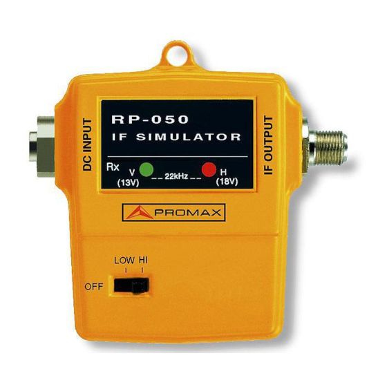
3 OPERATING INSTRUCTION 3.1 Description of the controls and elements Figure 1.- Front view [1] IF OUTPUT Output connector Frequency pilots output. On receiver Test mode this jack will be connected with the IF input jack (SAT-antenna input) of the SAT-Receiver. [2] OFF - LOW - HIGH Power / attenuation mode switch With this switch, different attenuation modes of the RP-050 can be selected:... -
Page 8: Operating Instructions
3.2 Operating Instructions 3.2.1 Using combined with a TV level meter The RP-050 has been specially designed for using joint to PROMAX’s TV level meters, which are able to tune the Satellite band like PROLINK-4/4C Premium, PROLINK-3/3C Premium or MC-377+ MC-377+ including the OP-377-63 option. - Page 9 Figure 2.- Checking a TV SAT - UHF installation. 1.- Separate the installation section that is desired to check from the general panel or from one of the jack outlets of the TV signal distribution network. 2.- Connect the RP-050 OUTPUT [1] connector to one of the ends from section under test, and use the TV level meter (RF input) on the other.
- Page 10 If, in addition, the level meter sound is tuned to 7.02 MHz (± 0.2 MHz), a tone of approximately 1 kHz will be audible in the TV level meter. Consequently, the correct equalisation of the selected installation section will be able to be verified. IMPORTANT REMARK: Video carriers generated by RP-050 are FM-modulated, therefore the picture withs bars transmitted at UHF band...
-
Page 11: Sat-Receiver Test
3.2.2 SAT-receiver test Figure 3.- SAT-receiver test Connect jack [1] RECEIVER to the RP-050 with the IF - input jack (SAT-antenna input) of the SAT-receiver to be tested. Connect SAT-receiver and television set (SCART-socket or RF- connector). Switch on SAT-receiver and television set, in case of connection via SCART-socket, switch television set to the AV-channel. -
Page 12: Maintenance
4 MAINTENANCE The method of maintenance to be carried out by the user consists of cleaning the cover. All other operations should be carried out by authorised agents or by personnel qualified in the service of instruments. 4.1 Cleaning recommendations CAUTION Do not use scented hydrocarbons or chlorides solvents.
Need help?
Do you have a question about the Promax and is the answer not in the manual?
Questions and answers