
Subscribe to Our Youtube Channel
Related Manuals for wtw System 2020 3G

Summary of Contents for wtw System 2020 3G
- Page 1 OPERATING MANUAL ba77049e03 05/2018 IQ S ENSOR System 2020 3G CONTROLLER MIQ/MC3 AND TERMINAL/CONTROLLER MIQ/TC 2020 3G...
- Page 2 IQ S System 2020 3G ENSOR Copyright © 2018 Xylem Analytics Germany GmbH Printed in Germany. ba77049e03 05/2018...
-
Page 3: Table Of Contents
Components of the system 2020 3G ........ - Page 4 IQ S System 2020 3G ENSOR 3.6.2 Stacked mounting of MIQ modules: ........45 3.6.3...
- Page 5 IQ S System 2020 3G ENSOR USB interface ............104 4.9.1...
- Page 6 Outputs of the System 2020 3G ........
- Page 7 IQ S System 2020 3G ENSOR 7.10.2 Behavior in non-operative condition ........203 7.11 Maintenance condition of the sensors .
- Page 8 IQ S System 2020 3G ENSOR ba77049e03 05/2018...
-
Page 9: Overview
System operating manual (ring binder) ENSOR Operating manuals for components and options (e.g. field bus) figure 1-1 Structure of the IQ S System 2020 3G operating manual ENSOR The IQ S operating manual has a modular structure like the ENSOR IQ S system itself. -
Page 10: The Iq Sensor Net System 2020 3G
ENSOR means that the essential functional units of the measuring system are distributed in components that can be individually compiled for special applications. The essential functional units of the IQ S System 2020 3G include: ENSOR Controller Terminal ... - Page 11 IQ S System 2020 3G Overview ENSOR PC, Smartphone, Tablet PC Webserver email Internet Fieldbus UMTS EtherNet/IP Modbus TCP Profinet Router Alternative fieldbus linking (Industrial) Ethernet-LAN USB flash drive Modbus RTU Data transfer/ PROFIBUS DP software updates/ electronic RS 485...
- Page 12 IQ S System 2020 3G Overview ENSOR PC, Smartphone, Tablet PC Webserver email Internet Fieldbus UMTS Router Alternative fieldbus linking Ethernet-LAN USB flash drive Modbus RTU Data transfer/ PROFIBUS DP USB- software updates/ Ethernet electronic adapter RS 485 Radio Radio module...
-
Page 13: Functions In The Iq Sensor Net
IQ S System 2020 3G Overview ENSOR 1.2.2 Functions in the IQ S ENSOR The functions of the IQ S are provided by the system (controller) and ENSOR the retrofitting components. Details on the functions listed can be found in the relevant system or components operating manuals. -
Page 14: Possible Ways To Communicate With The Iq Sensor Net
IQ S System 2020 3G Overview ENSOR Function Operating manual Daily load diagram, weekly load diagram, System monthly load diagram Monitoring functions System (sensors, system) Fieldbus interface 1.2.3 Possible ways to communicate with the IQ S ENSOR Digital communi- The IQ S... -
Page 15: Components Of The System 2020 3G
(e.g. temperature). In the system 2020 3G, digital WTW single sensors and mul- tiple sensors can be used: Single sensors provide a main measured value and normally a secondary →... - Page 16 IQ S System 2020 3G Overview ENSOR Each main measured value occupies a sensor location in the IQ S . A multiple sensor with two active main measured values ENSOR thus occupies two sensor locations. The available sensor locations can be occupied by any single or multiple sensors.
- Page 17 IQ S System 2020 3G Overview ENSOR Component or resource Maximum number Output channels, can be occupied by: – Current outputs – Relay outputs – Valve outputs Power supply modules (e.g. MIQ/PS) MIQ/JB branching modules Signal amplifier modules MIQ/JBR ("repeaters")
- Page 18 IQ S System 2020 3G Overview ENSOR The following diagram shows an IQ S system with two mounting vari- ENSOR ants (figure 1-4). stacked mounting distributed mounting MIQ/TC 2020 3G (as Terminal) MIQ/PS MIQ/CR3 MIQ/MC3(-...) MIQ/JB MIQ/JB Po w Po w...
-
Page 19: Miq Modules
IQ S System 2020 3G Overview ENSOR 1.2.5 MIQ modules Depending on their type, the MIQ modules have specific features (e.g. control- ler, relays, digital interfaces). All MIQ modules have a standard housing with the following features (figure 1-5): P o w... - Page 20 IQ S System 2020 3G Overview ENSOR Module lid with hinge Common charac- Due to its wide opening angle, the lid provides a large space for working teristics of the inside the module (e.g. for connecting lines to the terminal strip).
-
Page 21: Controller Miq/Mc3
IQ S System 2020 3G Overview ENSOR Controller MIQ/MC3 The controller does the following jobs: Control and monitoring of all IQ sensors Control and monitoring of all current and relay outputs Continuous diagnosis of the system, i.e. the information and error messages... -
Page 22: Miq/Tc 2020 3G Terminal/Controller
IQ S System 2020 3G Overview ENSOR MIQ/TC 2020 3G terminal/controller The terminal/controller MIQ/TC 2020 3G can be used in the IQ S ENSOR either as controller plus terminal (see section 1.4.1) or just as a terminal (see section 1.4.2). -
Page 23: Miq/Tc 2020 3G As Controller Plus Terminal
IQ S System 2020 3G Overview ENSOR The keys have the following functions: Keys Designation Functions <M> – Displays the measured values <C> – Starts the calibration process for the selected sensor <S> – Opens the 180 - System settings menu <OK>... -
Page 24: Miq/Tc 2020 3G Just As A Terminal
ENSOR breakdown. Thus, the operating security of the system is significantly increased. For this purpose the System 2020 3G regularly carries out an automatic backup of the system configuration during regular terminal operation. System configu-... -
Page 25: Status Led
IQ S System 2020 3G Overview ENSOR functions are carried out. Relay- and current interfaces, MIQ/3-PR, MIQ/3-MOD and RS485 operate without restrictions. Constraints The following functions are not supported: Continuation of the datalogger mode of the main controller Continuation of the digital communication of the main controller if the commu- nications interface is connected to the main controller. -
Page 26: Ethernet Interface
IQ S System 2020 3G Overview ENSOR – Log book – IQ LabLink data Connection of an electronic key for simple access to the system when access control is switched on (see section 5.3.4) Connection of a USB hub for the reproduction of the USB interface. -
Page 27: Behavior Of The Iq Sensor Net If A Components Fails
IQ S System 2020 3G ENSOR Overview During the restart, an entry informing of the power failure is made in the log book. 1.6.2 Behavior of the IQ S if a components fails ENSOR If the operating voltage is too low, the LEDs on the MIQ modules extinguish. -
Page 28: Availability Of The System
1.6.4 Compatibility of the controllers of the System 2020 3G (MIQ/MC3, MIQ/TC 2020 3G) with components of an existing IQ S ENSOR system If a controller of the System 2020 3G replaces a controller in an existing IQ S system, the following compatibilities apply: ENSOR... - Page 29 IQ S System 2020 3G Overview ENSOR Existing IQ S Compatibility ENSOR system (controller) System 2020 XT All existing components of the existing system (MIQ/MC2, are fully compatible with a controller (MIQ/MC3, MIQ/TC 2020 XT) MIQ/TC 2020 3G) System 2020 >The following terminal components are not...
-
Page 30: Safety
IQ S System 2020 3G Safety ENSOR Safety Safety information 2.1.1 Safety information in the operating manual This operating manual provides important information on the safe operation of the system. Read this operating manual thoroughly and make yourself familiar with the system before putting it into operation or working with it. The operating manual must be kept in the vicinity of the system so you can always find the in- formation you need. -
Page 31: Safe Operation
Safe operation 2.2.1 Authorized use The authorized use of the IQ S System 2020 3G consists of its use ENSOR in online analysis. Only the operation and running of the sensor according to the instructions and technical specifications given in this operating manual is autho- rized (see chapter 10 T ). -
Page 32: Installation
IQ S System 2020 3G Installation ENSOR Installation Scope of delivery Controller MIQ module MIQ/MC3 or Terminal/Controller MIQ/TC 2020 3G Only for MIQ/MC3: – Safety screw to secure the terminal/controller to an MIQ module – Option: with MODBUS or PROFIBUS connection ... -
Page 33: Basic Principles Of Installation
IQ S System 2020 3G Installation ENSOR Basic principles of installation 3.2.1 System planning START – Number and types of the sensors required – Measuring locations to be designed Planning criteria – Number of operating locations required – Distances – Infrastructure, process environment etc. -
Page 34: Requirements Of The Measurement Location
IQ S System 2020 3G Installation ENSOR 3.2.2 Requirements of the measurement location The respective measurement locations of all IQ S components must ENSOR meet the environmental conditions specified in section 10.1 G ENERAL SYSTEM DATA Controlled Work on the open instrument (e.g. during mounting, installation, maintenance) -
Page 35: Installation Guidelines For Lightning Protection
IQ S System 2020 3G Installation ENSOR Installation guidelines for lightning protection When installing and using the IQ S instrumentation, particularly in ENSOR outdoor areas, adequate protection against (electrical) surges must be provid- ed. A surge is a summation phenomenon of surge voltage and surge current. It is generated through the indirect effect of a lightning event or switching opera- tion in the mains, in the grounding system and in information technology lines. - Page 36 IQ S System 2020 3G Installation ENSOR contact cover provides improved insulation against the electric fields of a thunderstorm event through the extension of the air and creepage paths. 5 It is recommended to attach a metallic or nonmetallic sun shield to each out- side location of any IQ S instrumentation.
-
Page 37: Drawing Up The Power Rating
IQ S System 2020 3G Installation ENSOR an open air location. Drawing up the power rating General The IQ S supplies all components with low voltage as well as digital ENSOR information communication via a shielded 2-wire line. Due to this characteristic, the following factors must be taken into account in the... - Page 38 IQ S System 2020 3G Installation ENSOR IQ sensors Power requirement [W] ® VisoTurb 700 IQ (SW) ® ViSolid 700 IQ (SW) ® Plus AmmoLyt 700 IQ ® Plus NitraLyt 700 IQ ® Plus VARiON 700 IQ Spectral sensors ®...
- Page 39 IQ S System 2020 3G Installation ENSOR Terminal, Controller Power requirement [W] MIQ/MC3 MIQ/MC3PR MIQ/MC3-MOD MIQ/TC 2020 XT MIQ/TC 2020 3G USB devices Power requirement [W] USB memory approx. 0.5 ... 2 USB Ethernet adapter approx. 0.5 ... 2 Determining the...
-
Page 40: Effect Of The Cable Length
IQ S System 2020 3G Installation ENSOR ® + 1 SensoLyt 700 IQ + 0.2 18.7 + 1 MIQ/CR3 + 3.0 21.7 + 1 MIQ/TC 2020 3G + 3.5 25.2 The number or MIQ power supply modules required in the... - Page 41 IQ S System 2020 3G Installation ENSOR Determining the A diagram is used to determine whether an additional MIQ power supply module length of the cable is necessary for the planned installation. To do so, the length of the cable section section must be determined.
- Page 42 IQ S System 2020 3G Installation ENSOR To make it easier it is assumed that all consumers are placed at the end of the cable section. 1000 9 10 11 12 13 14 15 Sum of the power consumption of all consumers...
-
Page 43: Optimum Installation Of Miq Power Supply Modules
IQ S System 2020 3G Installation ENSOR tion of 650 m. Is the power supply with one MIQ power supply module sufficient? At which point must a further MIQ power supply module be installed if neces- sary? Proceeding: Enter both values as a point in the diagram (point "x" in figure 3-3). -
Page 44: Connecting System Components
IQ S System 2020 3G Installation ENSOR Connecting system components 3.6.1 General information The IQ S system components are connected to form a functioning ENSOR unit in the following ways: Stacked mounting of MIQ modules Up to three MIQ modules can be installed and mechanically connected with one another to form a stack at a single location. -
Page 45: Stacked Mounting Of Miq Modules
IQ S System 2020 3G Installation ENSOR 3.6.2 Stacked mounting of MIQ modules: For optimum stability, a maximum of three MIQ modules can be mounted in any one stack. Only one MIQ power supply module may be mounted per module stack. - Page 46 IQ S System 2020 3G Installation ENSOR Variant 1: Stack expansion forwards Preparing the stack mounting t a p t f e e lm r n e t a g u f k n t ie n t a le b...
- Page 47 IQ S System 2020 3G Installation ENSOR Mounting the contact base figure 3-5 Mounting the contact base (variant 1) 5 Contact base 6 Tapping screws 7 Countersunk screws Only IQ Sensor Net products may be used in the IQ Sensor Net.
- Page 48 IQ S System 2020 3G Installation ENSOR Premounting the ISO blind nuts figure 3-6 Mounting the contact base (variant 1) 8 Cheese-head screws 9 ISO blind nuts Insert the cheese-head screws (pos. 8 in figure 3-5) with the plastic washers in the drilled mounting holes in the enclosure and loosely screw in the ISO blind nuts (pos.
- Page 49 IQ S System 2020 3G Installation ENSOR Attach the prepared MIQ module to the lid of the back MIQ module. At the same time, ensure that the two clips on the front MIQ module click into place in the lid of the back MIQ module. Subsequently, tighten the two screws (pos.
- Page 50 IQ S System 2020 3G Installation ENSOR Variant 2: stack expansion backwards Preparing the stack mounting t a p t f e e lm r n e t a g u f k n t ie n t a le b...
- Page 51 IQ S System 2020 3G Installation ENSOR Mounting the contact base figure 3-10 Mounting the contact base (variant 1) 5 Contact base 6 Tapping screws 7 Countersunk screws Only use the plastic tapping screws supplied for attaching the con- tact base. They ensure the correct fit.
- Page 52 IQ S System 2020 3G Installation ENSOR Premounting the ISO blind nuts figure 3-11 Premounting the ISO blind nuts (variant 2) 8 Cheese-head screws 9 ISO blind nuts Insert the cheese-head screws (pos. 8 in figure 3-11) with the plastic washers in the drilled mounting holes in the module lid and loosely screw in the ISO blind nuts (pos.
- Page 53 IQ S System 2020 3G ENSOR Installation Stacking the MIQ modules figure 3-12 Stacking the MIQ modules (variant 2) Attach the prepared MIQ module to the back of the front MIQ module. At the same time, ensure that the two clips on the front MIQ module click into place in the lid of the back MIQ module.
-
Page 54: Distributed Mounting Of Miq Modules
IQ S System 2020 3G Installation ENSOR figure 3-13 Closing the enclosure (variant 2) 10 Countersunk screws Close the back MIQ module and fix it with the two countersunk screws (pos. 5 in figure 3-13). 3.6.3 Distributed mounting of MIQ modules... - Page 55 IQ S System 2020 3G Installation ENSOR Materials required 1 x SNCIQ or SNCIQ/UG connection cable (see chapter 11 A CCESSORIES AND OPTIONS Wire end sleeves for 0.75 mm wire cross-section with matching crimping tool 1 x cable gland with seal (scope of delivery of MIQ module).
- Page 56 IQ S System 2020 3G Installation ENSOR Connecting the The SNCIQ and SNCIQ/UG cables are connected to the terminal strip in the cables same way as the SACIQ sensor connection cable (see section 3.6.4): Open the MIQ module. Select any SENSORNET connection. At the same time, look out for the SENSORNET designation.
-
Page 57: Connecting Iq Sensors
IQ S System 2020 3G Installation ENSOR Tighten the cap nut (pos. 3 in figure 3-15). Check the position of the SN terminator switch and correct it if neces- sary (see section 3.10.1). Close the MIQ module. figure 3-16 Closing the cable opening... - Page 58 IQ S System 2020 3G Installation ENSOR Differentiating For the simpler correlation of measured value and measurement location, the IQ sensors of the system provides the option of giving each IQ sensor a user-defined name (see same type in the section 5.4.1).
- Page 59 IQ S System 2020 3G Installation ENSOR SACIQ figure 3-17 Connecting the SACIQ cable with the IQ sensor 1 Plug head connector 2 Coupling ring Plug the socket of the SACIQ sensor connection cable onto the plug head connector of the IQ sensor. At the same time, rotate the socket so that the pin in the plug head connector (1) clicks into one of the two holes in the socket.
-
Page 60: Installing Terminal Components
IQ S System 2020 3G Installation ENSOR 3.6.5 Installing terminal components The terminal component is the operating and control unit of the IQ S ENSOR It serves as an input and output device and is necessary to operate the IQ S... - Page 61 IQ S System 2020 3G Installation ENSOR For the temporary docking of a mobile terminal, do not remove the whole contact cover. Leave it hanging on the side of the MIQ module. After removing the terminal, replace the cover again to protect the contacts.
-
Page 62: Installation Of The Miq Modules At The Installation Location
IQ S System 2020 3G Installation ENSOR To dock the terminal component tightly onto the module lid, the in- terlocking lever is fixed in position with a strong spring. To protect any inadvertent removal of the terminal component, fix the interlocking lever in place with the screw (pos. -
Page 63: Mounting On A Mounting Stand With The Ssh/Iq Sun Shield
IQ S System 2020 3G Installation ENSOR (section 3.7.4). Top hat rail mounting: The back MIQ module of a module stack or a single MIQ module is mounted on a 35 mm top hat rail with the aid of a bracket in accordance with EN 50022, e.g. - Page 64 IQ S System 2020 3G Installation ENSOR Screw the sun shield (pos. 1 in figure 3-20) with the four hexsocket head screws (pos. 2), the washers (pos. 3) and the clamps (pos. 4) at the required height on the mounting stand from the back.
-
Page 65: Mounting Under The Sd/K 170 Sun Shield
IQ S System 2020 3G Installation ENSOR Mounting the MIQ module under the sun shield figure 3-22 Mounting the MIQ module on the SSH/IQ sun shield Position the MIQ module on the sun shield and fix it into place with the two screws (pos. -
Page 66: Panel Mounting
IQ S System 2020 3G Installation ENSOR Tools Phillips screwdriver. Mounting the MIQ module under the sun shield figure 3-23 Mounting the MIQ module on the SD/K 170 sun shield 1 Countersunk screws 2 Cheese-head screws Remove the two countersunk screws (pos. 1 in figure 3-23) and swing open the module lid. - Page 67 IQ S System 2020 3G Installation ENSOR The front MIQ module of the preassembled module stack must be removed in order to install the stack. After the installation of the front MIQ module, the remaining part of the stack can be added to the in- stalled MIQ module (see section 3.6.2 - Variant 2).
-
Page 68: Top Hat Rail Mounting
IQ S System 2020 3G Installation ENSOR Tighten the screws (pos. 2). Screw in the screws (pos. 3) until the screws rest snugly against the panel. 3.7.5 Top hat rail mounting Materials required THS/IQ kit for top hat rail mounting (see chapter 11 A... -
Page 69: Electrical Connections: General Instructions
IQ S System 2020 3G Installation ENSOR To unhook the MIQ module, press it downwards and pull it forwards at the bottom. Electrical connections: General instructions Cable glands All electric cables are fed from below via prepared openings in the enclosure of the MIQ modules. - Page 70 IQ S System 2020 3G Installation ENSOR sealing ring 20 x 15 x 1 mm extension piece M16/M20 sealing ring 24 x 19 x 2 mm cable gland M20 figure 3-27 Cable gland, large If necessary, you can order other sizes of cable gland (see...
-
Page 71: Connecting The Voltage Supply
IQ S System 2020 3G Installation ENSOR Connecting the voltage supply How to connect the power supply is described in detail in the operating manual of the MIQ power supply module (e.g. MIQ/PS, MIQ/24V). WARNING If the power supply is connected incorrectly, there may be danger to life from electric shock. - Page 72 IQ S System 2020 3G Installation ENSOR Definitions Main line Longest cable section with terminator switches at its ends. The terminator switches on both ends must be set to ON. If all MIQ modules are at one location, i. e. in a module stack, the length of the main line is zero (star-shaped wir- ing).
-
Page 73: Start Checklist And System Start
IQ S System 2020 3G Installation ENSOR Terminator Terminator switches are located in each MIQ module between the two SEN- switches SORNET connections on the right of the terminal strip (designation "SN TERMINATOR"): SN Terminator SENSORNET 2 SENSORNET 1 figure 3-30 Terminator switches 3.10.2 Start checklist and system start... - Page 74 IQ S System 2020 3G Installation ENSOR Start checklist: 1 Is the sum of the power consumption of the components smaller than the sum of the power delivery of all MIQ power supply modules (see section 3.2.1)? 2 Are all IQ S...
- Page 75 IQ S System 2020 3G Installation ENSOR For details for the configuration of the MIQ/TC 2020 3G, see section 1.4. During the first system start, select the configuration of the MIQ/ TC 2020 3G. The selected configuration can be changed by reset- ting the system to the default condition and a restart.
-
Page 76: Checking The Voltage Supply
IQ S System 2020 3G Installation ENSOR Assign a name to each IQ sensor after putting it into operation for the first time so you can identify it more easily. How to assign a sen- sor name is described in section 5.4.1 on page 123. -
Page 77: System Extension And Modification
IQ S System 2020 3G Installation ENSOR . 10 C ER r. 9 r. - N figure 3-34 Voltage LED on the MIQ module You can measure the voltage that is actually available at the MIQ modules or IQ sensors (see section 9.2.2). - Page 78 IQ S System 2020 3G Installation ENSOR WARNING If the system is switched on while the MIQ/PS power sup- ply module is open, there is a danger to life due to possi- ble hazard of electric shock from line voltage. There is also a danger to life inside the relay output modules (e.g.
- Page 79 IQ S System 2020 3G Installation ENSOR New modules are first registered on the system when the measured value display is opened. Replacing The replacement of components is described in detail in section 9.4 R EPLACING components SYSTEM COMPONENTS ba77049e03...
-
Page 80: Operation
IQ S System 2020 3G Operation ENSOR Operation Terminal The IQ S is operated via a terminal. For this, the following options ENSOR with the same functional range are available: MIQ/TC 2020 3G, configured as (mobile) terminal or as (permanently installed) controller. -
Page 81: Overview Of The Operating Elements
IQ S System 2020 3G Operation ENSOR 4.1.1 Overview of the operating elements The terminal is equipped with a large display for the clear presentation of current measured values, the graph of measured values, status displays and message texts. <M>... -
Page 82: Display
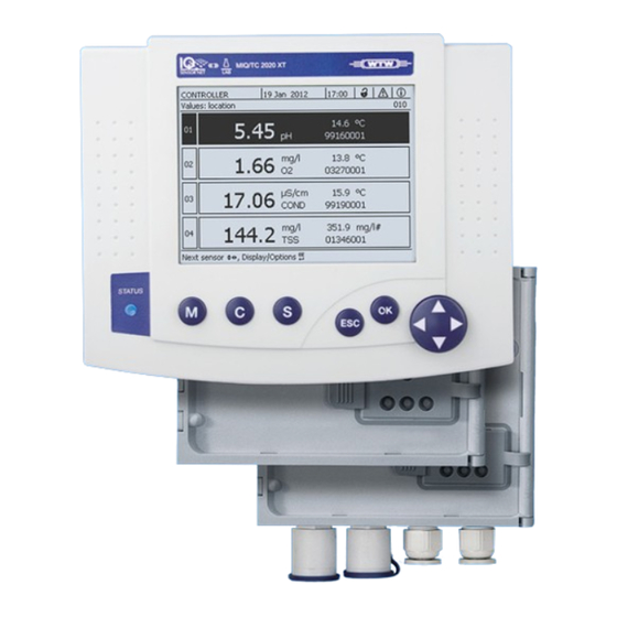
IQ S System 2020 3G Operation ENSOR 4.1.2 Display The display contains the following information: figure 4-2 Display 1 Name of the display 2 Name of the terminal alternating with the controller function (CONTROLLER or BACKUP CONTROLLER) 3 Date 4 Time... - Page 83 IQ S System 2020 3G Operation ENSOR Measured value The measured value display contains the following information for each display IQ sensor/differential sensor: figure 4-3 Display - measured value display 1 Consecutive numbering of the measured values 2 Main measured value 3 Unit and parameter of the main measured value 4 Name of the sensor (to enter name: see section 5.4.1...
-
Page 84: Keys
IQ S System 2020 3G Operation ENSOR 4.1.3 Keys Function <M> Display measured values <C> Start calibration of the IQ sensor selected in the measured value display <S> Open the Settings menu <ESC> Change to the higher menu levels or abort entries without storing them <OK>... -
Page 85: Navigating In Menus, Lists And Tables
IQ S System 2020 3G Operation ENSOR Short operating instructions are given in the help lines on the dis- play. Examples of the operating principles are given below: Navigation in menus, lists and tables (see chapter 4.2.1) Entering text and numerical values (see chapter 4.2.2) -
Page 86: Entering Texts Or Numerals
IQ S System 2020 3G Operation ENSOR <ESC> Return to a higher level with <M> Switch to the measured value display with 4.2.2 Entering texts or numerals You can assign names to IQ sensors, MIQ output modules, terminals and loca- tions. - Page 87 IQ S System 2020 3G Operation ENSOR figure 4-6 Edit list of sensors The following letters, numerals and special characters can be en- tered: AaBb..Zz0..9µ%&/()+-=><!?_ °. < > Select a letter or numeral with <OK> Confirm the letter with The character appears behind the last letter.
-
Page 88: Access To The Iq Sensor Net With Active Access Control
IQ S System 2020 3G Operation ENSOR Add a new character < > Select the character to be added with and confirm with <OK> Delete the last character < > <OK> Select the character with and confirm with ... -
Page 89: Display Of Current Measured Values
IQ S System 2020 3G Operation ENSOR Extended access control with instrument block: Press the any button. In the password query, enter the password with the arrow keys and confirm with OK. Further details on access control (see section 5.3) -
Page 90: Displaying A Single Measured Value
IQ S System 2020 3G Operation ENSOR figure 4-8 Display/Options < > <OK> Select and confirm a display type with . The selected display type is enabled 4.4.1 Displaying a single measured value The measured value is shown numerically and as a bar graph on the Measured values (1 sensor) display. -
Page 91: Displaying Eight Measured Values
IQ S System 2020 3G Operation ENSOR figure 4-10 Values: location -> Measured values (4 sensors) 4.4.3 Displaying eight measured values Up to eight measured values of IQ sensors or differential sensors are shown on the display at the same time. - Page 92 IQ S System 2020 3G Operation ENSOR Measured value list of selected sensor (numerical display) figure 4-12 Daily load of selected sensor (example) 1 Display 2 Range of the graphical display The time range (x-axis) corresponds to the selected type of display (1 day, 1 week, 1 month).
-
Page 93: Transmitting Recorded Measurement Data To A Pc
IQ S System 2020 3G Operation ENSOR figure 4-13 Monthly load of selected sensor (example) < > Move the cursor (X) along the measured value curve with The cursor (X) marks the selected measured value. Switch to the next display option with a shorter display period with <OK>... -
Page 94: Messages And Log Book
IQ S System 2020 3G Operation ENSOR < > Using , select the menu item, Display local values or all val- <OK> ues and confirm with . The measured value display switches between the display of the sensors at the measurement location and all sensors. - Page 95 IQ S System 2020 3G Operation ENSOR Structure of the log book figure 4-14 Log book of entire system 1 Message category (error or info symbol) 2 Module that triggered the message. SYS System (Universal Transmitter, controller) S01 IQ sensor (number 01)
- Page 96 IQ S System 2020 3G Operation ENSOR I 2 152 a b c figure 4-15 Structure of the message code Information Explanation Short message The three-digit short form of the message form contains the following information on the message: Category (a), type (b) and type number Category ...
-
Page 97: Viewing Detailed Message Texts
IQ S System 2020 3G Operation ENSOR The log book shows the current status at the point of time it was opened. If new messages arrive while a log book is open, these do not appear in the log book. As usual, you are informed of new mes- sages by flashing info or error symbols. -
Page 98: Acknowledge All Messages
IQ S System 2020 3G Operation ENSOR With the Acknowledge all messages function you can acknowledge all messag- es at the same time (see section 4.5.4). Message texts are stored in the modules that caused them. There- fore, further information on a log book entry for an IQ sensor such as, e.g. -
Page 99: Calibration Entries In The Log Book
IQ S System 2020 3G Operation ENSOR tion history of selected sensor overview. All calibration data are stored in the IQ sensor. In order to view the calibration data of an IQ sensor, the IQ sensor must be connected to the IQ S and must be ready for operation. -
Page 100: Status Info Of Sensors And Outputs
IQ S System 2020 3G Operation ENSOR Status info of sensors and outputs The display of the instrument status provides a simple overview of the current modes of sensors (sensor info) and outputs in the IQ S ENSOR The status display can be reached in the Settings/Service/List of all components menu (see section 4.10). -
Page 101: General Course When Calibrating, Cleaning, Servicing Or Repairing An Iq Sensor
IQ S System 2020 3G Operation ENSOR General course when calibrating, cleaning, servicing or repairing an IQ sensor When an IQ sensor is calibrated, cleaned, serviced or repaired, the mainte- nance condition for the relevant IQ sensor should always be switched on. -
Page 102: Maintenance Condition Of Iq Sensors
IQ S System 2020 3G Operation ENSOR 4.8.1 Maintenance condition of IQ sensors The following diagram gives you a general overview of when an IQ sensor is in the maintenance condition. Maintanance Sensor condition ON cleaning Measured value Measured value... -
Page 103: Switching On The Maintenance Condition
IQ S System 2020 3G Operation ENSOR 4.8.2 Switching on the maintenance condition Switch on the maintenance condition manually when you want to clean, service or repair (remove and replace) an IQ sensor. <M> Call up the measured value display with Select the sensor you want to switch on the maintenance condition for <... -
Page 104: Usb Interface
IQ S System 2020 3G Operation ENSOR If a power failure occurs, the outputs automatically are in the non- operative condition (relays: open, current output: 0 A; see compo- nent operating manual of the output module). After the end of the power failure the outputs work as defined by the user again. - Page 105 IQ S System 2020 3G Operation ENSOR Data backup <M> Switch to the measured value display with <S> Open the 100 - Settings menu with < > <OK> to open the Data transfer to USB memory menu. < >...
-
Page 106: Saving The System Configuration Manually
IQ S System 2020 3G Operation ENSOR You can cancel the data saving process by highlighting and confirm- < > <OK> ing the Cancel menu item with . In this case the data will not be stored to the USB memory device. -
Page 107: Restore System Configuration
IQ S System 2020 3G Operation ENSOR 4.9.3 Restore system configuration If the MIQ/TC 2020 3G is operated as a backup controller, resto- ration of the last automatic backup of the system configuration is au- tomatically suggested when a new controller is identified by the system. -
Page 108: Ensor Net
ENSOR available on the Internet under www.WTW.com. The instrument software is transferred to the System 2020 3G via the USB port and with the aid of a USB memory device. While a software update is running, the yellow LED on the controller MIQ/MC3 flashes rapidly. -
Page 109: The Miq/Tc 2020 3G In Its Function As Terminal And Backup Controller
IQ S System 2020 3G Operation ENSOR While a software update is running, the voltage LEDs on the MIQ/MC3 controller indicate the status of the software update: LEDs Status Status of the update Next step Yellow Flashing rap- Update of the controller is... - Page 110 IQ S System 2020 3G Operation ENSOR Sequence of IQ Sensor Net MIQ/TC 2020 3G Time axis MIQ/TC 2020 3G memory main controller controller opera- tion (simplified) Regular Regular controller operation terminal operation Controller operat Saving of the system configuration...
- Page 111 IQ S System 2020 3G Operation ENSOR The procedure in detail: Normal operation During normal operation the main controller carries out regular controller operation. The MIQ/TC 2020 3G (configured as a terminal) works as a regular terminal. The MIQ/TC 2020 3G (configured as a terminal) backs up the system config- uration: –...
- Page 112 IQ S System 2020 3G Operation ENSOR uration and, if necessary, offers to restore the backed-up system configura- tion to the main controller. If the system configuration is not transferred to the main controller, the first regular backup from the main controller to the MIQ/TC 2020 3G is carried out after 2 minutes.
-
Page 113: Settings/Setup
IQ S System 2020 3G Settings/setup ENSOR Settings/setup Selecting the language A list shows all the available system languages. <S> Open the Settings menu with < > <OK> Using , select and confirm the menu item, Lan- guage. The Language display opens. - Page 114 IQ S System 2020 3G Settings/setup ENSOR Illumination brightness Illumination brightness (standby) Display contrast Status LED Terminal settings cannot be made with access via IQ W ONNECT figure 5-2 Terminal settings Setting Selection/Val- Explanation Terminal name AaBb..Zz...
-
Page 115: Access Control
IQ S System 2020 3G Settings/setup ENSOR Terminal name in The terminal name of the controller is part of the network address of the the Ethernet IQ S system. ENSOR network To create a valid network address for the IQ S... - Page 116 IQ S System 2020 3G Settings/setup ENSOR appears. User right The current user right is shown on the display with the following symbols. Simple access Symbol User rights control Settings are All functions in the system are accessible to unlocked...
- Page 117 IQ S System 2020 3G Settings/setup ENSOR < > <OK> <OK> Press to select a function and to confirm. The dialog window for entering the password opens. < > <OK> Press to enter the valid password and press <OK>...
-
Page 118: Activating The Extended Access Control
IQ S System 2020 3G Settings/setup ENSOR figure 5-4 System settings -> Change password < > <OK> Using , select and confirm the menu item, Change password. The dialog window for entering the password opens. < > <OK> ... - Page 119 User rights as for Viewer. the function Instrument block active: was activated The System 2020 3G is blocked. Only the IQ S logo is dis- ENSOR played. Access only with password. Switching on the If necessary, switch off the simple access control (see section 5.3.1).
- Page 120 IQ S System 2020 3G Settings/setup ENSOR figure 5-5 Settings -> Access control -> Extended access control The instrument automatically generates a password for each user right. This password can be accepted or changed. < > <OK> Press to select a user right and confirm with If necessary, change the password in the selection dialog and/or save the password to a connected USB memory.
-
Page 121: Activating The Instrument Block For A Terminal
IQ S System 2020 3G Settings/setup ENSOR Forgotten the password? Then you can release the IQ S ENSOR again (see section 14.1). 5.3.3 Activating the instrument block for a terminal Use the Device lock function to protect the terminal on which this function is ac- tivated –... -
Page 122: Electronic Key
ENSOR word to USB memory. The USB memory thereby becomes an electronic key. When the electronic key is connected to the System 2020 3G, the user right stored there with the relevant password is automatically read out. The user of the electronic key is logged on to the system with his user right without any fur- ther password prompt. -
Page 123: Access To The Iq Sensor Net With Active Access Control
IQ S System 2020 3G Settings/setup ENSOR 5.3.5 Access to the IQ S with active access control ENSOR Simple access control Administrator access after entering the password in order to take over a changed setting: The protection is automatically reactivated after the one setting was changed. -
Page 124: Changing The Display Position
IQ S System 2020 3G Settings/setup ENSOR < > Using, highlight the name of a sensor and confirm with <OK> figure 5-6 Edit list of sensors < > <OK> <OK> Enter the name with and confirm with (see section 5.4.1). -
Page 125: Erasing Inactive Sensor Datasets
IQ S System 2020 3G Settings/setup ENSOR figure 5-7 Edit list of sensors -> Set display position < > Using , select the menu item, Set display position and con- <OK> firm with A dialog window opens. < >... -
Page 126: Setting Up Sensors/Differential Sensors
IQ S System 2020 3G Settings/setup ENSOR figure 5-8 Edit list of sensors -> Erase inactive sensor < > Using , select Erase inactive sensor and confirm with <OK> The dialog window for the security prompt appears. < >... -
Page 127: Erasing A Differential Sensor
IQ S System 2020 3G Settings/setup ENSOR figure 5-9 Settings of sensors and diff. sensors -> Link with... < > <OK> Using , select a sensor and confirm with The sensors are linked. The link in both sensors is entered in the Edit list of sensors overview. - Page 128 IQ S System 2020 3G Settings/setup ENSOR figure 5-10 Settings of sensors and diff. sensors -> Erase differential sensor < > Using , select Erase differential sensor and confirm with <OK> The differential sensor is erased. ba77049e03 05/2018...
-
Page 129: Settings For Sensors/Differential Sensors
IQ S System 2020 3G Settings/setup ENSOR Settings for sensors/differential sensors Sensor settings include the measured parameter, measuring range and, if nec- essary, compensations. Enhanced sensor For certain sensors, special representation types and settings are available in functions the menu, Extended sensor functions. An example for an enhanced sensor function is the editing of measured values as a graphic representation with cur- sor and zoom function (e.g. -
Page 130: Sensor-Sensor Link
IQ S System 2020 3G Settings/setup ENSOR Sensor-sensor link (automatic offset of an influencing quantity) The Sensor-sensor link function automatically makes available the measured value of a sensor to another sensor in the IQ S system. ENSOR Example: D.O. sensors measure the D.O. partial pressure and use the solubility function Measuring the D.O. - Page 131 IQ S System 2020 3G Settings/setup ENSOR ® function (e.g. TetraCon 700 IQ measures the salinity - salinity is quoted dimensionless). – The manually entered value for the static correction is set to the mean value of the influence quantity (e.g. salinity value) of the test sample.
- Page 132 IQ S System 2020 3G Settings/setup ENSOR -> figure 5-13 System settings Sensor-sensor link < >< > Using , highlight a parameter to be linked, and confirm with <OK> The displayed list includes all sensors that measure an influence quan- ®...
-
Page 133: Erasing A Sensor-Sensor Link
IQ S System 2020 3G Settings/setup ENSOR Behavior if there is Cause Behavior no measured value – Sensor failure – The manually entered value for the influence quan- for the influence tity is automatically used for correction. quantity An exclamation mark (!) indicates the interrupted link. -
Page 134: Editing The List Of Outputs
IQ S System 2020 3G Settings/setup ENSOR Editing the list of outputs The Edit list of outputs display provides an overview of all outputs, links and in- active datasets (see section 9.4.3). In the Edit list of outputs display, you can: ... -
Page 135: Erasing An Inactive Dataset For An Miq Output Module
IQ S System 2020 3G Settings/setup ENSOR figure 5-16 Edit list of sensors 5.8.2 Erasing an inactive dataset for an MIQ output module An inactive dataset for an MIQ output module arises if the system receives no signals from a registered MIQ output module. Inactive datasets can be recog- nized by a question mark, e.g. -
Page 136: Output Links/Settings
IQ S System 2020 3G Settings/setup ENSOR figure 5-17 Edit list of outputs -> Erase output module < > <OK> Using , select Erase output module and confirm with The dialog window for the security prompt appears. < >... - Page 137 IQ S System 2020 3G Settings/setup ENSOR figure 5-18 Location display Entering the name The name of the measurement location is displayed in the line with the name of of a measuring the display. 15 characters are available for the name of the measurement loca- location tion.
-
Page 138: Alarm Settings
IQ S System 2020 3G Settings/setup ENSOR 5.10 Alarm settings 5.10.1 General information Under this menu item you can specify reactions on certain alarm events. An alarm event is when a certain measured value (limiting value) of a sensor is exceeded or undercut. - Page 139 IQ S System 2020 3G Settings/setup ENSOR In the Sensor column, the sensor number (corresponding to the list of sensors) and series number is named. < > Select an alarm A01 to A20 to be edited with . To set up a new alarm without entry select in the Sensor column.
- Page 140 IQ S System 2020 3G Settings/setup ENSOR Edit the setting table. The required operating steps are described in detail in section 4.2 G ENERAL OPERATING PRINCIPLES Alarm links setting table Menu item Selection/Values Explanations Measured variable Main variable Main variable designates the actual measured parameter of the sensor (e.g.
-
Page 141: Alarm Output To Display
IQ S System 2020 3G Settings/setup ENSOR 5.10.3 Alarm output to display When an alarm event occurs, a window with a text message appears. figure 5-22 Example of an alarm message on the display 1 Alarm no. Axx and date and time of the alarm event... -
Page 142: System Settings
IQ S System 2020 3G Settings/setup ENSOR section 5.11.4. Prerequisite A connection to the Internet exists (see chapter 6 E THERNET CONNECTION For critical alarm events take into account that Email messages may possibly be received delayed. 5.11 System settings System settings include: ... -
Page 143: Location Altitude / Average Air Pressure
IQ S System 2020 3G Settings/setup ENSOR figure 5-23 Date/Time < > <OK> Press to select and confirm a number. The next field is highlighted, e.g. Month. Complete the entries on the display Date/Time. The clock in the MIQ/MC3 and MIQ/TC 2020 3G bridges periods of power failure for several hours. -
Page 144: Tcp/Ip Settings
IQ S System 2020 3G Settings/setup ENSOR figure 5-24 Location altitude/Air pressure < > Press to select Set altitude of location or Set air pressure <OK> and confirm with < > Press to change the values for Loc. altitude or Air pressure <OK>... - Page 145 IQ S System 2020 3G Settings/setup ENSOR figure 5-25 TCP/IP settings < > <OK> Press to select and confirm a menu item. An entry field or selection list opens up. Setting Selection/Val- Explanation DHCP The IQ S is configured as a DHCP cli- ENSOR ent.
-
Page 146: E-Mail
IQ S System 2020 3G Settings/setup ENSOR Setting Selection/Val- Explanation Subnet mask Address Subnet mask (if DHCP No). The subnet mask depends on the network size (for small networks: e.g. 255.255.255.0). DNS server Address Entry for fieldbuses not required. For a connection with the Internet (if DHCP No), e.g.:... -
Page 147: Settings Bus Interfaces
IQ S System 2020 3G Settings/setup ENSOR figure 5-26 E-mail settings < > <OK> Press to select and confirm a menu item. An entry field or selection list opens up. Setting Selection/Val- Explanation SMTP Server Address Address of the SMTP server of the email pro- vider through which the email will be sent. -
Page 148: Function Code
IQ S System 2020 3G Settings/setup ENSOR munication of the IQ S with a fieldbus. Prerequisite: An interface to a ENSOR fieldbus is available (hardware, optional). For details, see operating manual ba77010 "IQ S Fieldbus linking", ENSOR for download under www.WTW.com. -
Page 149: Setting The Recording Interval (Dt) And Recording Duration (Dur.)
IQ S System 2020 3G Settings/setup ENSOR 5.12.1 Setting the recording interval (dt) and recording duration (Dur.) <S> Open the Settings menu with < > <OK> Using , select and confirm the menu item, Mea- sured value logging. The Measured value logging display opens. - Page 150 IQ S System 2020 3G Settings/setup ENSOR with the oldest data is erased. All other data is retained. For inactive IQ sensors, the Dur. setting can only be reduced. <ESC> Switch to the selection of columns with < > <OK>...
-
Page 151: Ethernet Connection
IQ S System 2020 3G Ethernet connection ENSOR Ethernet connection The Ethernet interface for the IQ S system is on the MIQ/MC3 con- ENSOR troller. If, in the IQ S system, no MIQ/MC3 controller is avail- ENSOR able, an Ethernet connection can also be realized via the USB inter- face of the MIQ/TC 2020 3G controller and an external USB Ethernet adapter. - Page 152 IQ S System 2020 3G Ethernet connection ENSOR Insofar as the settings affect network subscribers of third-party vendors (e.g. the router), only a general reference is made here to the setting. For details, of the menus in which the settings are made, please refer to the respective operating manual for your device.
-
Page 153: Communication In A Local Network (Lan)
IQ S System 2020 3G Ethernet connection ENSOR USB Ethernet With the MIQ/TC 2020 3G as controller, the connection to the Ethernet takes adapter for MIQ/ place via a USB Ethernet adapter. Suitable are USB/Ethernet adapters with Asix TC 2020 3G AX88772(A/B/C) chip set. -
Page 154: Communication On The Internet
IQ S System 2020 3G Ethernet connection ENSOR Prerequisites Details / Examples / Designations Network services WINS server (e.g. on the terminal device DHCP and DNS servers or router) (for network access in the LAN via the name of the MIQ/MC3 or MIQ/... - Page 155 IQ S System 2020 3G Ethernet connection ENSOR Prerequisite Details / Examples / Designations Internet services Internet access with data DSL connection flat rate, e.g.: Mobile wireless connection (SIM card) Internet service which A public IP address makes the router publicly (e.g.
-
Page 156: Ethernet Connection With Installation Outdoors (Miq/Mc3)
IQ S System 2020 3G Ethernet connection ENSOR Ethernet connection with installation outdoors (MIQ/MC3) When plugged in, the RJ45 socket is not sufficiently protected against moisture. With open air installation, the Ethernet cable must therefore be clamped directly onto the PCB of the MIQ/MC3 controller to ensure a safe Ethernet communica- tion. - Page 157 IQ S System 2020 3G Ethernet connection ENSOR LSA terminal strip SHIELD CLAMP ENTHERNET CABLE figure 6-3 Ethernet connection via terminal strip Strip the Ethernet cable for approx. 2 cm and untwist the Rx+, Rx-, Tx+ and Tx wires. Carefully slash the cable shield (foil + netting) lengthwise and put it backwards over the cable sheath (pos.
-
Page 158: Establishing The Connection With The Iq S
IQ S System 2020 3G Ethernet connection ENSOR Establishing the connection with the IQ S via a net- ENSOR work 6.3.1 Opening the IQ W ONNECT The web server of the MIQ/MC3 provides functions for the (remote) operation of the MIQ/MC3 and for the data exchange (e.g. with a PC) via a network address. -
Page 159: Iq Web Connect Terminal
IQ S System 2020 3G Ethernet connection ENSOR figure 6-4 IQ W start page ONNECT The IQ W start page of the MIQ/MC3 provides links to ONNECT the following functions of the controller (MIQ/MC3 or MIQ/ TC 2020 3G): "IQ W Terminal"... -
Page 160: Iq Web Connect Datalogtransfer
IQ S System 2020 3G Ethernet connection ENSOR You can save data to a USB memory device connected to the instru- ment (similar to operation of the instrument). To save data to a PC, select the function "IQ W DatalogTransfer" (see ONNECT section 6.3.3). - Page 161 IQ S System 2020 3G Ethernet connection ENSOR For processing you can open the csv file, e.g. with Microsoft Excel. figure 6-6 Example of a CSV file after being imported into Microsoft Excel 1 Identification of the measurement data (from left to right, line 1) –...
-
Page 162: Communication With Fieldbuses (Miq/Mc3[-Xx])
The system configuration contains the same data as with the backup via the USB :interface (see section 4.9.2). Communication with fieldbuses (MIQ/MC3[-XX]) Details on communication with fieldbuses are given in the operating manual ba77010e ("IQ S fieldbus linking"). The current version can be found ENSOR on the Internet at www.WTW.com. ba77049e03 05/2018... -
Page 163: Troubleshooting
IQ S System 2020 3G Ethernet connection ENSOR Troubleshooting The IQ S provides an Ethernet interface for the connection of the ENSOR IQ S to private networks, company networks and public networks. ENSOR To establish accessibilty of the IQ S in a public network (e.g. - Page 164 IQ S System 2020 3G Ethernet connection ENSOR Here is a selection of possible causes for network/connection problems. If there are other connection problems, contact your network administrator or a network specialist. No network Cause Remedy connection – Ethernet hardware defective, e.g.
- Page 165 IQ S System 2020 3G Ethernet connection ENSOR Cause Remedy – Ports which are used by the – Have your network administrator IQ S are already assign free ports to you ENSOR assigned to other devices in the – Specify the port (1-65535) manu- network (e.g.
-
Page 166: Technical Network Terms
IQ S System 2020 3G Ethernet connection ENSOR Technical network terms DHCP DHCP is a network service which automatically assigns an IP address (Dynamic Host Config- to a network subscriber. uration Protocol) In local networks, this function is mostly carried out by the router. - Page 167 IQ S System 2020 3G Ethernet connection ENSOR Port A port is the communication interface of an application (possible port numbers: 0-65535). Some ports (port numbers) are reserved for special applications, e.g.: 21: FTP (File Transfer Protocol) 25: SMTP (Simple Mail Transfer Protocol) ...
-
Page 168: Outputs
IQ S System 2020 3G Outputs ENSOR Outputs Outputs of the System 2020 3G Extension modules with outputs extend your IQ S System 2020 3G ENSOR by the following types of outputs: Outputs MIQ module Current (C) Relays (R) Valve (V) -
Page 169: Basic Information On Relay Functions
IQ S System 2020 3G Outputs ENSOR Sensor-controlled Manual control Alarm contact Basis information on the use of relay outputs is given in section 7.2. Current outputs Recorder (see section 7.7) PID controller Fixed current value Valve outputs ... - Page 170 IQ S System 2020 3G Outputs ENSOR Limit indicators can be used in the following way: Monitoring a limiting value using a relay: when a limiting value (upper or lower limiting value) is exceeded or undercut, a relay switches. The Open or Close relay actions are possible in each case (see page 170).
-
Page 171: Proportional Output
IQ S System 2020 3G ENSOR Outputs A switching delay (t) can be set up for each relay for switching processes. This is the time period for which a limiting value must be exceeded before the relay switches. This prevents frequent switching if the measured values are close to the limiting value. - Page 172 IQ S System 2020 3G Outputs ENSOR Output with two Switching frequency f or relays Pulse width Proportional bands Relay 1 and 2 Measured value Relay 1 Relay 2 figure 7-3 Relay output of the pulse-width output 1 Start value...
- Page 173 IQ S System 2020 3G Outputs ENSOR Relay Time [s] figure 7-4 Output with two relays The cycle duration (T) is made up of the turn-on and turn-off switching duration (t ) of the relay together. While the selected cycle duration...
- Page 174 IQ S System 2020 3G Outputs ENSOR switched more often or less often. Relay t = 0.3 s Time [s] figure 7-5 Relay output of frequency output While the selected switching duration (t = 0.3 s) always remains con- stant, the switching frequency at which the relay switches changes depending on the measured value.
- Page 175 IQ S System 2020 3G ENSOR Outputs Switching frequency f or Pulse width Max. Min. Measured value Start value End value figure 7-6 Positive characteristic curve Switching frequency f or Pulse width Max. Min. Measured value End value Start value...
- Page 176 IQ S System 2020 3G Outputs ENSOR The proportional output range begins above the initial value. If the proportional Positive character- range is undercut or exceeded, the selected behavior comes into force. istic curve Pulse width v [%] Cycle duration T...
- Page 177 IQ S System 2020 3G ENSOR Outputs The proportional output range begins below the initial value. If the proportional Negative charac- range is undercut or exceeded, the selected behavior comes into force. teristic curve Pulse width v [%] Cycle duration T...
-
Page 178: Entering / Editing The Name Of An Output
IQ S System 2020 3G Outputs ENSOR Entering / editing the name of an output For easier identification of the outputs, an individual name can be given to each output in the Edit list of outputs overview. <S> Open the Settings menu with <... -
Page 179: Linking The Output With A Sensor
IQ S System 2020 3G Outputs ENSOR Linking the output with a sensor <S> Open the Settings menu with < > <OK> Using , select and confirm the menu item, Sys- tem settings -> Settings of outputs and links. -
Page 180: Deleting A Link With An Output
IQ S System 2020 3G Outputs ENSOR Deleting a link with an output If a link between a current or relay output and a sensor is no longer required, you can erase the link. <S> Open the Settings menu with <... -
Page 181: Setting The Relay Outputs (Miq/Cr3, Miq/R6)
IQ S System 2020 3G Outputs ENSOR Setting the relay outputs (MIQ/CR3, MIQ/R6) <M> Call up the measured value display with <S> Open the Settings menu with < > Using , highlight the menu item, Settings of outputs and <OK>... -
Page 182: Relay Action
IQ S System 2020 3G Outputs ENSOR Function Description The relay output is not used. No function see section 7.6.2 System monitoring see section 7.6.3 Sensor monitoring see section 7.6.4 Limit indicator see section 7.6.5 Frequency controller see section 7.6.6 Pulse-width output see section 7.6.7... -
Page 183: System Monitoring
IQ S System 2020 3G Outputs ENSOR 7.6.2 System monitoring Function The System monitoring function enables the monitoring of system errors. In or- der to set up the System monitoring function for a relay output, the relay output must not be linked with a sensor (see section 7.4). -
Page 184: Sensor Monitoring
IQ S System 2020 3G Outputs ENSOR 7.6.3 Sensor monitoring Function The Sensor monitoring function enables the monitoring of sensor errors and the monitoring of the maintenance condition. In order to set up the Sensor monitoring function for a relay output, the relay out- put must be linked with a sensor (see section 7.4). -
Page 185: Frequency Controller
IQ S System 2020 3G Outputs ENSOR value LL, Hysteresis UL and Hysteresis LL settings. The fundamentals of the function are described in the introductory chapter (see section 7.2.2). In order to set up the Limit indicator function for a relay output, the relay output must be linked with a sensor (see section 7.4). - Page 186 IQ S System 2020 3G Outputs ENSOR Settings Setting Selection/Values Explanation Main variable Main variable designates the Measured variable Adjoining variable actual measured parameter of the sensor (e.g. pH, oxy- gen, etc.). Adjoining variable desig- nates an additional mea- sured parameter (e.g.
-
Page 187: Pulse-Width Output
IQ S System 2020 3G Outputs ENSOR 7.6.6 Pulse-width output Function The characteristic of the pulse width output is laid down in the Start value, End value, Pulse width (v) min. and Pulse width (v) max. settings. The fundamentals of the function are described in the introductory chapter (see section 7.2.3). - Page 188 IQ S System 2020 3G Outputs ENSOR Function The Cleaning function enables the time-controlled automatic start of the sensor cleaning function with the aid of a relay of the combination output module. The relay controls the valve module MIQ/CHV and switches on or off the com- pressed air.
- Page 189 IQ S System 2020 3G Outputs ENSOR Setting Selection/Values Explanation 0 ... 900 s Time extension to allow the Adjustment time sensor to adjust to the test sample after cleaning. * With short cleaning intervals, the adjustable values for the Cleaning duration and Adjustment time are limited.
- Page 190 IQ S System 2020 3G Outputs ENSOR t1a t1b relay condition closed open 00:00 04:00 12:00 20:00 24:00 Time figure 7-16 Cleaning 1 Reference time Begin of a cleaning cycle (t1) Begin of the specified Cleaning duration (t1a) 2 End of the specified Cleaning duration (t1a)
-
Page 191: Sensor-Controlled
IQ S System 2020 3G Outputs ENSOR dition. The linked outputs are only released after the maintenance condition was terminated manually. The next cleaning cycle will be performed at the time set up. In case of a power failure, all relays open. The cleaning cycle is can- celed. -
Page 192: Manual Control
IQ S System 2020 3G Outputs ENSOR 7.6.9 Manual control Function The Manual control function can be used to test the operativeness of an instru- ment that is connected to the relay. To do so, close or open the relay manually and, while doing so, check the behavior of the connected instrument. -
Page 193: Recorder
IQ S System 2020 3G Outputs ENSOR < > Using , highlight a line for a current output (Cx) in the column <OK> Feature. Confirm with The Settings of outputs and links display opens. < > Using , highlight the menu item, Current output, and confirm <OK>... - Page 194 IQ S System 2020 3G Outputs ENSOR down in the Recorder type, Start value and End value settings. Settings Setting Selection/Values Explanation 0 to 20 mA or Recorder type 4 to 20 mA (sensor depen- Minimum spacing: Start value ≤ 5 % of the measuring range...
-
Page 195: Pid Controller
IQ S System 2020 3G Outputs ENSOR 7.7.2 PID controller Function The PID controller function can use an output as a controller output. The regu- lator can be configured as a Proportional regulator with switchable Integral and Differential regulator parts (PID Controller). - Page 196 IQ S System 2020 3G Outputs ENSOR the following controller types can be configured: Regulator type td [s] ti [s] P controller 1 to 9999 PI controller 1 to 9999 PD controller 1 to 9999 1 to 9999 PID controller...
- Page 197 IQ S System 2020 3G ENSOR Outputs Regulation of the oxygen concentration Application exam- Sensor: TriOxmatic 700 IQ (measuring range: 0 to 60 mg/l) Control parameter Value 4 mg/l Nominal value 10 % of the measuring range or 6 mg/l...
- Page 198 IQ S System 2020 3G Outputs ENSOR The controller works with the following amplification: mg/l mg/l Within the proportional range an increase of the concentration by 1 mg/l causes a reduction of the output current by 1 mA. If the measured con- centration is 5 mg/l, for example, 11 mA is output: ⋅...
-
Page 199: Fixed Current Value
IQ S System 2020 3G Outputs ENSOR Setting Selection/Values Explanation 0 ... 20 mA Current value on the output if the measured value equals the Nominal value 0 ... 9999 s Hold-back time: Integral part of the controller (0 = not effective) 0 ... -
Page 200: Setting The Valve Output (Miq/Chv Plus)
IQ S System 2020 3G Outputs ENSOR Setting the valve output (MIQ/CHV Plus) <M> Call up the measured value display with <S> Open the Settings menu with < > Using , highlight the menu item, Settings of outputs and <OK>... -
Page 201: Checking The Condition Of The Outputs
IQ S System 2020 3G Outputs ENSOR Function Description Manual control see section 7.6.9 < > <OK> Make the settings for the relay outputs with < > <OK> Highlight and confirm Save and quit with The new settings are stored. -
Page 202: Behavior Of Linked Outputs
IQ S System 2020 3G Outputs ENSOR <M> <ESC> Exit the 394 - Status of output channels window with 7.10 Behavior of linked outputs 7.10.1 Behavior in case of error For linked relay outputs or current outputs, you can determine the behavior of the outputs in case of errors. -
Page 203: Behavior In Non-Operative Condition
IQ S System 2020 3G Outputs ENSOR 7.10.2 Behavior in non-operative condition An output is non-operative when no function is activated for the output. An output becomes non-operative in case of Power failure (As soon as the supply voltage is sufficient again, the non-operative condition of the outputs ends. -
Page 204: Switching On The Maintenance Condition
IQ S System 2020 3G Outputs ENSOR If the maintenance condition is activated for a sensor, the measured values or status indicators of this sensor flash in the measured value display. 7.11.1 Switching on the maintenance condition <M> Call up the measured value display with Select the sensor you want to switch on the maintenance condition for <... -
Page 205: Maintenance And Cleaning
IQ S System 2020 3G ENSOR Maintenance and cleaning Maintenance and cleaning Maintenance Maintenance Component Maintenance activities IQ sensors Depending on the type of sensor (see the component operating manual of the sensor) Other components No maintenance required Cleaning MIQ modules and Clean components mounted in the open of gross contamination as necessary. -
Page 206: What To Do If
IQ S System 2020 3G What to do if ... ENSOR What to do if ... Information on errors Log book The IQ S system performs a comprehensive cyclical self test during ENSOR operation. While doing so, the system identifies all states that deviate from nor- mal operation and enters corresponding messages in the log book (information or error message). - Page 207 IQ S System 2020 3G What to do if ... ENSOR the following causes: The voltage supply has been interrupted The available voltage is not sufficient; the voltage is below the warning range. These two cases can be differentiated with a voltmeter.
- Page 208 IQ S System 2020 3G What to do if ... ENSOR Tapping points for measuring the voltage ...+ U ...+ U figure 9-1 Tapping points for measuring the voltage: Front ...+ U ...+ U ...+ U ...+ U SENSORNET 1...
-
Page 209: Tips For Clearing Errors In The Voltage Supply
IQ S System 2020 3G What to do if ... ENSOR 9.2.3 Tips for clearing errors in the voltage supply Admissible values for the internal voltage supply (+U) are given in section 10.1. Supply voltage not Cause Remedy present or in the –... -
Page 210: Other Errors
IQ S System 2020 3G What to do if ... ENSOR Cause Remedy – Component is defective – Check the log book for error messages (for details on the log book, see section 4.5). – If no log book entry exists, send the component back. - Page 211 IQ S System 2020 3G ENSOR What to do if ... The system no Cause Remedy longer reacts to – System error Reset the system: entries – Switch off the power supply and switch it on again after 10 s "Error"...
-
Page 212: Replacing System Components
IQ S System 2020 3G What to do if ... ENSOR Replacing system components It is always possible to replace components and assign a substitute if the software state of the substitute component is as high as or higher than the software version of the original component. - Page 213 IQ S System 2020 3G ENSOR What to do if ... The maximum number of data sets (active and inactive datasets) for IQ sensors is limited to 20 in the IQ S system 2020 3G. ENSOR When this number is reached, no further IQ sensor can be installed.
- Page 214 IQ S System 2020 3G What to do if ... ENSOR <M> Switch to the measured value display with . The component data- base is updated. The following display appears (example): figure 9-3 510 - Add/replace sensor < > <OK>...
-
Page 215: Adding And Replacing Miq Output Modules
IQ S System 2020 3G What to do if ... ENSOR < > Select the required inactive dataset with and confirm with <OK> . The system changes to the measured value display. The IQ sensor takes over all settings of the inactive dataset. As soon as the IQ sensor is ready for operation, it delivers a measured value. - Page 216 IQ S System 2020 3G What to do if ... ENSOR To erase inactive datasets, see section 5.8.2. If an MIQ output module is connected to the system when an inactive dataset is present, the following cases are possible: Case 1:...
- Page 217 IQ S System 2020 3G What to do if ... ENSOR figure 9-5 410 - Add/replace output module < > <OK> Select the required option with and confirm with – If Add new output module was selected, the system changes directly to the measured value display.
-
Page 218: Technical Data
IQ S System 2020 3G Technical data ENSOR Technical data 10.1 General system data Test certificates Ambient Temperature conditions Mounting/installation/ + 5 °C ... + 40 °C (+ 41 ... +104 °F) maintenance Operation - 20 °C ... + 55 °C (- 4 ... + 131 °F) Storage - 25 °C ... - Page 219 IQ S System 2020 3G Technical data ENSOR Relationship between the supply voltage U, the LED status on the MIQ module Internal voltage and the log book entries (figure 10-1): supply U [V] 16,4 14,4 14,2 figure 10-1 Relationship of supply voltage - LED states - log book...
- Page 220 IQ S System 2020 3G Technical data ENSOR Meter safety Applicable norms – EN 61010-1 – UL 61010-1 – CAN/CSA C22.2#61010-1 EMC product and EN 61326 EMC requirements for electrical resources for con- system character- trol technology and laboratory use istics –...
-
Page 221: General Data Of Miq Modules
IQ S System 2020 3G Technical data ENSOR 10.2 General data of MIQ modules Technical data on special MIQ modules are given in the respective operating manuals. Dimensions Front view Lateral view Rear view Stack mounting figure 10-2 Dimension drawing of MIQ module (dimensions in mm) - Page 222 IQ S System 2020 3G Technical data ENSOR Mechanical Maximum number of 3 plus terminal component structure MIQ modules in a mod- ule stack Enclosure material Polycarbonate with 20 % glass fiber Weight Approx. 0.5 kg Type of protection IP 66...
-
Page 223: Miq/Mc3
IQ S System 2020 3G Technical data ENSOR 10.3 MIQ/MC3 Dimensions Lateral view Front view Rear view figure 10-3 Dimension drawing of the MIQ/MC3 (dimensions in mm) Terminal strip SHIELD CLAMP SENSORNET 2 SENSORNET 1 ENTHERNET CABLE figure 10-4 Terminal strip inside the enclosure:... - Page 224 IQ S System 2020 3G Technical data ENSOR Electrical data Supply voltage Max. 24 VDC via the IQ S (for details, ENSOR see section 10.1 G ENERAL SYSTEM DATA Power consumption MIQ/MC3 2.5 W MIQ/MC3-PR 3.0 W MIQ/MC3-MOD 3.0 W...
-
Page 225: Terminal/Controller Miq/Tc 2020 3G
IQ S System 2020 3G ENSOR Technical data 10.4 Terminal/Controller MIQ/TC 2020 3G Dimensions Front view: Lateral view: Stack mounting figure 10-5 Dimension drawing of the MIQ/TC 2020 3G (dimensions in mm) Mechanical Enclosure material ASA (Acrylonitrile Styrene Acrylesterpolymer) structure Weight Approx. - Page 226 IQ S System 2020 3G Technical data ENSOR USB-A interface Version USB 2.0 Usage Download of measurement data, software updates, electronic key Immediately close the USB connection with the protective cover when you have removed the USB device. When the USB connection is open, there is a danger of corrosion.
-
Page 227: Space Required By Mounted Components
IQ S System 2020 3G Technical data ENSOR 10.5 Space required by mounted components Wall mounting and top hat rail mounting figure 10-6 Space required for wall and top hat rail mounting: (dimensions in mm) 1 Space for screw driver... -
Page 228: Accessories And Options
Kit for mounting of MIQ modules on a 35 mm top hat rail in THS/IQ 480 050 accordance with EN 50022 Other accessories for the IQ S are given in the WTW cat- ENSOR alog or on the Internet. ba77049e03 05/2018... -
Page 229: Messages
IQ S System 2020 3G Messages ENSOR Messages 12.1 Explanation of the message codes The log book contains a list with all the messages from all modules. Each mes- sage consists of message code, date and time. You can obtain more detailed information by opening the full message text (see section 4.5). -
Page 230: Informative Messages
IQ S System 2020 3G Messages ENSOR Message code Message text EI8152 Connection to the component instable * Check installation and cable lengths, Follow installation instructions * Set SN terminator switch acc. to operating manual * Check environmental effects * Component defective, contact service... -
Page 231: Index
IQ S System 2020 3G Index ENSOR Index External voltages ......207, 215 Access control .......... 115 Air pressure ..........143 Ambient conditions ......34, 218 Fieldbus ............162 Arrow keys 84, 169, 170, 173, 179, 182, 184, Function code ...........148 187, ....189, 191, 192, 199, 203, 204 Inactive dataset Basic components ........ - Page 232 IQ S System 2020 3G Index ENSOR Texts ............. 97 Single sensors ........15 Types ............ 94 Sensor-sensor link ........130 Monthly load diagram of selected sensor ... 91 Setting the date ........142 Multiple sensors ......... 15 Setting the time ........142 Settings ............
-
Page 233: Appendix
IQ S System 2020 3G Appendix ENSOR Appendix 14.1 Forgotten the password? (store separately if required) Extended access The administrator can view and change all stored passwords (see section 5.3). control If the IQ S is locked and the administrator password lost, you can un- ENSOR lock the system with a master password. -
Page 234: Default Password
IQ S System 2020 3G Appendix ENSOR figure 14-2System settings -> Display password <OK> Quit the display of the password with 14.2 Default password Simple access The password of the controller is set to 1000 in the delivery state. control... - Page 236 Weitere Informationen darüber, wie Xylem Ihnen helfen kann, finden Sie auf xyleminc.com ® Serviceadresse: Xylem Analytics Germany Sales GmbH & Co. KG Dr.-Karl-Slevogt-Str. 1 82362 Weilheim Germany Tel.: +49 881 183-325 Fax: +49 881 183-414 E-Mail wtw.rma@xyleminc.com Internet: www.WTW.com Xylem Analytics Germany GmbH Dr.-Karl-Slevogt-Str. 1 82362 Weilheim Germany...
Need help?
Do you have a question about the System 2020 3G and is the answer not in the manual?
Questions and answers