
Summary of Contents for SEDEMAC RD1031
- Page 1 ABSTRACT This manual is intended as an information guide for operating RD1031 Gateway which is a part of SEDEMAC’s R2D3 IIoT platform. Doc #SED-MAN-RD1031-002 Date: 21-Sep-2018 MANUAL FOR RD1031 Product Manual Version #0.00...
- Page 2 Any reference to trademarked product names used within this publication is owned by their respective companies. SEDEMAC Mechatronics Pvt. Ltd. reserves the right to change the contents of this document without prior notice.
- Page 3 ✓ For safety reasons, the manufacturer recommends that this equipment be installed and serviced by an authorized service personnel. Follow all applicable state and local electrical codes. ✓ Efficient and safe operation of RD1031 Gateway can be acquired only if the equipment is correctly operated, configured and maintained.
- Page 4 RD1031 SEDEMAC ✓ Do not wear damp clothing (particularly wet shoes) or allow skin surface to be damp when handling electrical equipment. ✓ Do not operate any electrical device or wires while standing in water, while barefoot, or while hands or feet are wet.
- Page 5 RD1031 SEDEMAC List of Abbreviation This list contains the list of acronyms used in this document and it can be used to refer their respective description. This list does not contain units of measure. Acronym Description Centre To Centre Genset Control Unit...
-
Page 6: Table Of Contents
Description of keys and LED indication ................21 LED Diagnostics ........................ 22 Reset Key Function ......................22 Firmware Upgradation ......................23 Mobile Flash Installation ....................23 Hardware connection of RD1031 Gateway and android mobile ........26 Firmware flashing ......................27 Notes ............................. 31 Page | iv... - Page 7 SEDEMAC List of Figures Figure 1: R2D3 architecture ......................1 Figure 2: RD1031 Gateway front fascia with terminal numbers ............2 Figure 3: 3 pin female (mating) connector ..................3 Figure 4: 2 pin female (mating) connector ..................4 Figure 5: SIM card holder ........................5 Figure 6: USB host connector ......................
- Page 8 Figure 41: Mobile Flash screen: select R2D3 in product categories ..........26 Figure 42: Mobile Flash screen: fetching selected category data ............ 26 Figure 43: RD1031 Gateway and android mobile hardware connection ......... 27 Figure 44: Mobile Flash screen: allow app to access USB device ..........27 Figure 45: Mobile Flash screen: ready to connect ................
- Page 9 RD1031 SEDEMAC List of Tables Table 1: Operating temperature ......................3 Table 2: Power supply specifications ....................3 Table 3: 3 -pin connector details ......................3 Table 4: RS485 connection details ....................4 Table 5: 2- pin connector details ......................4 Table 6: Power supply connection details ..................
-
Page 10: Introduction
MODBUS over RS485, which not only enables the user to remotely start & stop the generator, but also helps the user to change the modes of genset. RD1031 Gateway is features rich with 4G LTE, 2G, 3G Fall- back and Wi-Fi outbound communication. It also acknowledges alarms and relay the respective information to the appropriate contact person near the generator vicinity. -
Page 11: Product Features
50+ parameters displayed (configurable update time) for a fleet of up to 10,000 generators • RD1031 Gateway supports all SEDEMAC GCU’s MODBUS map 1.2 Product Features Following table gives a brief overview of various product features of the RD1031 Features list • RS485 •... -
Page 12: Hardware Specifications
Table 3: 3 -pin connector details Connector Manufacturer Female (Mating) Pitch Quantity (Nos) type 3-Pin Phoenix* 1881338 2.5 mm *https://www.phoenixcontact.com Below table gives the information about the terminal details of RD1031 for the RS485 connection purpose. Page | 3... -
Page 13: Figure 4: 2 Pin Female (Mating) Connector
Quantity (Nos) type 2-Pin Phoenix* 1881325 2.5 mm *https://www.phoenixcontact.com Below table gives the information about the terminal details of RD1031 for the power supply connection purpose. Table 6: Power supply connection details Terminal Phoenix Female (Mating) Name Description Sr. No. -
Page 14: Communication Ports
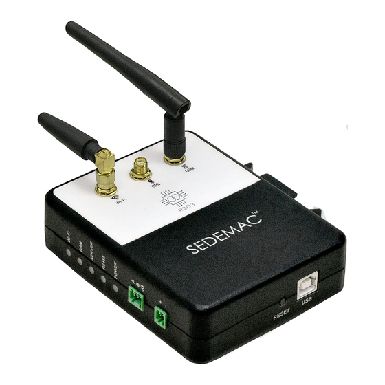
It is recommended to use industrial grade SIM card if the device is being installed inside the genset canopy. 2.3.4 USB Host Connector RD1031 Gateway connects to “Mobile Flash” utility through USB Type-B connector. Figure 6: USB host connector 2.3.5 Antenna Connector R2D3 Gateway uses three SMA antennae connectors for Wi-Fi, GPS and GSM. -
Page 15: Dimensions
Common-mode operating range and bus-pin fault protection up to ±70V • Maximum distance of line is 500m • Terminal number: 1, 2, 3 2.5 Dimensions Figure 8 This section gives overall dimension details of RD1031 Gateway. Refer Figure 8: RD1031 Gateway dimensions Page | 6... -
Page 16: Installation
3.1 SIM Card Installation RD1031 Gateway uses 4G/3G/2G network for the communication. A standard size SIM card slot is provided in the Gateway to use the 4G/3G/2G services. Follow the below steps to install SIM card in RD1031 Gateway. -
Page 17: Wi-Fi Configuration
RD1031 SEDEMAC Figure 10: SIM card Installation 3.2 Wi-Fi Configuration Figure 11: Wi-Fi Installation Page | 8... -
Page 18: Figure 12: R2D3 Droid Screen: Provisioning Menu
Open R2D3 Droid mobile app. Please make sure data connection of your phone is turned off. • Click on “Provisioning” menu. Figure 12: R2D3 Droid screen: provisioning menu • Select SEDEMAC Wi-Fi SSID from the drop-down list of ‘Device to configure’. Figure 13: R2D3 Droid screen: list of available devices Page | 9... -
Page 19: Figure 14: R2D3 Droid Screen: Selecting The Device
RD1031 SEDEMAC Figure 14: R2D3 Droid screen: selecting the device • Following screen will appear once the device connects successfully. Figure 15: R2D3 Droid screen: device connected successfully • Now select the available Wi-Fi network, enter the password and click the next arrow. -
Page 20: Figure 16: R2D3 Droid Screen: List Of Available Wi-Fi Networks
RD1031 SEDEMAC Figure 16: R2D3 Droid screen: list of available Wi-Fi networks Figure 17: R2D3 Droid screen: enter password Page | 11... -
Page 21: Figure 18: R2D3 Droid Screen: Connecting To The Wi-Fi Network
RD1031 SEDEMAC Figure 18: R2D3 Droid screen: connecting to the Wi-Fi network • Following screen will appear once the Wi-Fi connects successfully. Figure 19: R2D3 Droid screen: Wi-Fi connected successfully • Click “Configure”. Page | 12... -
Page 22: Figure 20: R2D3 Droid Screen: Device Configure
RD1031 SEDEMAC Figure 20: R2D3 Droid screen: device configure • Now it starts configuring the device. Figure 21: R2D3 Droid screen: configuring the device • Following screen will appear once the device is successfully configured. Page | 13... -
Page 23: Antenna Mounting
RD1031 SEDEMAC Figure 22: R2D3 Droid screen: device configured successfully 3.3 Antenna Mounting Mount the Wi-Fi, GPS and GSM antenna as shown in Figure 23. Figure 23: Antenna mounting Figure 24 shows antenna assembly on RD1031 Gateway. Page | 14... -
Page 24: Gateway Mounting
RD1031 on DIN rail. Refer Figure 28 Figure 29 If DIN rail is available for the mounting, then RD1031 Gateway can be mounted on DIN rail. 3.4.1 Snap Fit Mounting Figure 25 shows the screw mounting of bracket in control panel or on any mounting surface. The bracket uses M4 screws for the mounting. -
Page 25: Figure 25: Bracket Mounting With Screws
RD1031 SEDEMAC Figure 25: Bracket mounting with screws Press the RD1031 Gateway on the mounted bracket; “Click” sound confirms the proper fitting of the Gateway on bracket. Refer Figure 26 & Figure 27 Figure 26: Snap fit of RD1031 Gateway... -
Page 26: Figure 27: Snap Fit Assembly Of Rd1031
Figure 27: Snap fit assembly of RD1031 3.4.2 DIN Rail Mounting Follow below steps for RD1031 mounting with the help of DIN rail. 1. RD1031 Gateway has bracketed slot for DIN rail mounting. Slide the RD1031 Gateway over DIN rail as shown in Figure... -
Page 27: Figure 28: Rd1031 Gateway Mounting On Din Rail
RD1031 SEDEMAC Figure 28: RD1031 Gateway mounting on DIN rail shows final fitment of the RD1031 Gateway on DIN rail. Figure 29 Figure 29: DIN rail fitting Page | 18... -
Page 28: Rs485 Installation
RD1031 Gateway is connected to genset controller through RS485 interface. Make sure that the cable connecting RS485 terminals is shielded. Controller acts as slave and RD1031 Gateway acts as a master in the configuration. Make sure to check the slave ID of the controller and configure it to the master before installing. -
Page 29: Operation
SEDEMAC 4 Operation RD1031 Gateway communicates to the GCU/ECU, which monitors the genset at site. It also communicated with the server and transfers the information monitored by GCU. This information is recorded in the server. Figure 31: Operation of R2D3 4.1 Connection Details... -
Page 30: Description Of Keys And Led Indication
RD1031 SEDEMAC 4.2 Description of keys and LED indication Below illustrations shows different parts of the RD1031 Gateway. Refer Figure 33 Figure 33: Control keys function Page | 21... -
Page 31: Led Diagnostics
4. Mounting bracket 4.3 LED Diagnostics RD1031 Gateway is provided with five of LEDs for various indications. These LED indications are easy to understand and helpful to know the working status of the Gateway. Below table gives an information about the LED light indication for different purposes in different modes. -
Page 32: Firmware Upgradation
RD1031 SEDEMAC 5 Firmware Upgradation List of equipment: • The android mobile phones having OTG (On The Go) and data connectivity. • USB cable 2.0 Type B Figure 34: USB cable 2.0 Type B • According to the type of USB cable supported by the mobile phone, following types of OTG cable are used: Micro USB to USB 2.0 Type B... -
Page 33: Figure 37: Mobile Flash Screen: Install
RD1031 SEDEMAC Figure 37: Mobile Flash screen: install • Click on “OPEN” and allow app to access photos, media, and files on your device. Figure 38: Mobile Flash screen: open the app Page | 24... -
Page 34: Figure 39: Mobile Flash Screen: Allow Access Of Phone
RD1031 SEDEMAC Figure 39: Mobile Flash screen: allow access of phone • Tap “YES” to select Product categories. Figure 40: Mobile Flash screen: select product categories • Click on “R2D3” and save it. A screen will pop-up with a message “Data downloaded successfully”. -
Page 35: Hardware Connection Of Rd1031 Gateway And Android Mobile
Figure 42: Mobile Flash screen: fetching selected category data • This completes the software installation process. 5.2 Hardware connection of RD1031 Gateway and android mobile • Connect Android phone and target device with OTG cable & USB cables as shown in the image. -
Page 36: Firmware Flashing
RD1031 SEDEMAC Figure 43: RD1031 Gateway and android mobile hardware connection • Put RD1031 in programming mode. Refer Reset Key Function. 5.3 Firmware flashing • After successful hardware connection, click on Mobile Flash app, a message will pop-up on mobile screen, click on “OK”. -
Page 37: Figure 45: Mobile Flash Screen: Ready To Connect
RD1031 SEDEMAC Figure 45: Mobile Flash screen: ready to connect Figure 46: Mobile Flash screen: connected to RD1031 Do not remove USB cable during flashing. • Now click on “Flash” button. • An Alert message will pop-up to Turn ON airplane mode, click on “OK”. -
Page 38: Figure 47: Mobile Flash Screen: Alert For Turn On Airplane Mode
RD1031 SEDEMAC Figure 47: Mobile Flash screen: alert for turn on airplane mode • Go to your mobile setting and turn airplane mode ON. Figure 48: Mobile Flash screen: airplane mode on • Click on “Flash” option again & firmware will start updating. -
Page 39: Figure 49: Mobile Flash Screen: Updating Firmware
RD1031 SEDEMAC Figure 49: Mobile Flash screen: updating firmware • Once 100% of flashing of file completed, Click on “OK”. Figure 50: Mobile Flash screen: flashing completion Page | 30... -
Page 40: Notes
RD1031 SEDEMAC Notes Page | 31... - Page 41 RD1031 SEDEMAC Disclaimer: Due to continuous development, the details provided in this document are subject to change without any prior notice. SEDEMAC Mechatronics Pvt Ltd Technical Centre C9-10, C Block, MIDC Bhosari Pune 411026, India Manufacturing Plant G-1, MIDC, Phase-III Chakan...
Need help?
Do you have a question about the RD1031 and is the answer not in the manual?
Questions and answers