Table of Contents
Advertisement
Quick Links
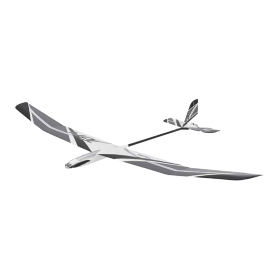
SPECIFICATIONS
Wingspan: 78.5 in [1995mm]
Length: 42 in [1065mm]
2
Wing Area: 498 in
[32.1 dm
Weight: 29– 31 oz [822– 879 g]
WARRANTY
Great Planes
®
Model Manufacturing Co. guarantees this kit to
be free from defects in both material and workmanship at the
date of purchase. This warranty does not cover any component
parts damaged by use or modification. In no case shall Great
Planes' liability exceed the original cost of the purchased kit.
Further, Great Planes reserves the right to change or modify this
warranty without notice.
In that Great Planes has no control over the final assembly or
material used for final assembly, no liability shall be assumed nor
accepted for any damage resulting from the use by the user of
READ THROUGH THIS MANUAL BEFORE STARTING CONSTRUCTION. IT CONTAINS IMPORTANT
INSTRUCTIONS AND WARNINGS CONCERNING THE ASSEMBLY AND USE OF THIS MODEL.
© 2018 Great Planes Model Mfg. A subsidiary of Hobbico,
8.4– 9.0 oz/ft 2
Wing
[25.6– 27.5 g /dm 2 ]
Loading:
Motor: RimFire .10 Outrunner
(Included with the Rx-R)
2
]
ESC: 40A
(Included with the Rx-R)
®
Inc.
INSTRUCTION MANUAL
Battery: 2S 2200mAh,
Propeller: 12 x 6.5 (included)
Radio: 4+ ch. radio, 4 servos
the final user-assembled product. By the act of using the
user-assembled product, the user accepts all resulting liability.
If the buyer is not prepared to accept the liability associated
with the use of this product, the buyer is advised to return
this kit immediately in new and unused condition to the
place of purchase.
To make a warranty claim contact:
greatplanes.com/support
3S 1800mAh LiPo
(LiPo not included)
(Servos included with the Rx-R)
GPMA1818/GPMA1819
Advertisement
Table of Contents

Related Manuals for GREAT PLANES Tori

Summary of Contents for GREAT PLANES Tori
- Page 1 To make a warranty claim contact: In that Great Planes has no control over the final assembly or greatplanes.com/support material used for final assembly, no liability shall be assumed nor accepted for any damage resulting from the use by the user of READ THROUGH THIS MANUAL BEFORE STARTING CONSTRUCTION.
-
Page 2: Table Of Contents
Make sure the aircraft is held securely until the battery has been disconnected. Thank you for purchasing the Great Planes Tori 2-meter EP Sailplane! The Tori features a carbon boom, folding prop While working on your plane, ALWAYS remove the propeller and fi berglass fuselage. -
Page 3: Lithium Battery Warning
ESC. With the included 12x6.5 folding propeller, material. Place it in a bucket, covering the battery with sand. either version of the Tori may be fl own on a 2S or 3S battery. The recommended motor, ESC and battery for the Tori: NEVER use water to try and put out a LiPo fi re. -
Page 4: Adhesives, Hardware And Other Accessories
Aileron Servo Cover Great Planes C.G. Machine (GPMR2400) ❍✱ 3/16" Heat shrink tubing (GPMM1056) (see page 17) GPMA4408 Decals ✱ These items not needed for Tori Rx-R For questions, contact: greatplanes.com/support KIT CONTENTS 1. Wing Halves 2. Pushrods 3. Wing Joiner 4. -
Page 5: Preparation
PREPARATION ASSEMBLE THE WING Hook Up the Ailerons You can assemble one wing at a time, or work on both wing halves simultaneously. The left wing is shown in the photos. ❏ 1. The canopy is held in place with wire rods at both ends. - Page 6 ❏ 6. Use medium-grit sandpaper to roughen the bottom portion of the two larger control horns so glue will adhere. Install a brass screw-lock connector into the top hole of both horns and secure with a nylon retainer as shown. Be ❏...
- Page 7 90° 90° Left Right ❏ 11. Connect the other end of the aileron servo extension wire to the receiver. Turn on the transmitter and power the receiver with a separate receiver battery (or the ESC connected to the receiver and your motor battery). With the servo powered and centered, install the servo arm to the servo so it will be perpendicular to the case—if necessary, use the Sub Trims in your transmitter programming to get...
-
Page 8: Install The Servo Covers
❏ ❏ 16. After the glue holding the servos to the wing has 2. Make certain you have everything on-hand to glue the dried, turn on the radio to center the servos. Holding the wings together including 30-minute epoxy, a mixing cup, a ailerons centered, connect the pushrods to the screw-lock mixing stick, an epoxy brush, masking tape and those paper connectors with an M2x3 Phillips machine-thread screw... -
Page 9: Mount The Wing
❏ 7. After the epoxy has hardened, carefully peel off the tape. ASSEMBLE THE FUSELAGE Any residual masking tape adhesive may be cleaned with another paper towel square dampened with naphtha (lighter Install the Fin and Stab fl uid). Areas of covering that may have lifted from removing the tape should be re-tightened with your covering iron. - Page 10 A. Tie a small loop in one end of the line. ❏ 4.Check for proper alignment of the fi n to the stab. Use 30-minute epoxy to glue the fi n into the stab (if the fi t is loose, add micro balloons to the epoxy). Use a small square to make sure the fi n is perpendicular to the stab while the epoxy hardens.
- Page 11 ❏ ❏ 8. Insert a T-pin into the front of the wing centered between 11. Remove the stab. Glue the stab into position with the two adjoining ribs. Loop the string over the T-pin. 30-minute epoxy using the pin and string to check alignment as done in the previous steps.
-
Page 12: Hook Up The Elevator And Rudder
Hook Up the Elevator and Rudder ❏ 4. Straighten the pushrod by removing the bend. ❏ ❏ 5. Prepare and install the other pushrod through the other 1. Mount the elevator and rudder servos as shown. (If your slot in the boom the same way – don’t forget to install the servos do not fi t, the servo tray may be trimmed as necessary.) small plastic tube fi rst! Drill 1/16"... -
Page 13: Install The Motor
❏ 8. Fit, then glue the top portion of the pushrod brace into position all the way up against the “lip” around the wing saddle—it isn’t critical where the brace is located forward and aft—where it fi ts best is fi ne. Make sure the brace doesn't interfere with the exit holes of the aileron servo leads. - Page 14 ❏ ❏ 2. Mount the motor with four M3x6 Phillips screws and a 5. Temporarily test-fi t the propeller/spinner assembly and small drop of threadlocker on the threads.The motor wires check the gap between the front of the fuselage and the should be oriented along the bottom of the fuselage.
- Page 15 A. Cut the motor wires to the desired length – about 1/2" ❏ 7. Cut a strip of the rougher, hook side of the included [13mm] is fi ne. adhesive-back hook-and-loop strip to a length of 3-3/8" [85mm] and apply to the top of the battery plate with CA glue. B.
-
Page 16: Final Assembly
1. Install the receiver so it will be secure, somewhat cushioned and so the antennas will be positioned according to the manufacturer’s instructions. In this Tori, we taped one of the antennas to the bottom of the fuselage before installing the receiver, then fi t the receiver under the pushrod guide brace with 1/4"... -
Page 17: Prepare The Model For Flight
PREPARE THE MODEL FOR FLIGHT Set the Control Throws CAUTION: The propeller should not yet be installed. If the propeller is installed on the motor, remove the propeller while operating the radio to check the throws. ❏ 2. Test-fi t the battery in place. Make sure it can be installed so that the discharge and balance leads will not contact the spinning motor. -
Page 18: Arm The Esc
Balanced advance the throttle slightly (just enough to make the motor nearer the aft end of the C.G. range the Tori will “fl oat” and turn) and turn off the transmitter. If the Fail Safe is set correctly, respond to lifting air a little better. -
Page 19: Balance The Model Laterally
In the case of a glider such as the Tori, it is pencils or screwdrivers that may fall out of shirt or jacket desirable to link the timer to the throttle stick so only motor pockets into the prop. -
Page 20: Flying
(unloaded) voltage after you land. The fi rst objective will be to get the Tori trimmed. Once trimmed Each cell in the pack should not be below 3.7V/cell. When...
Need help?
Do you have a question about the Tori and is the answer not in the manual?
Questions and answers