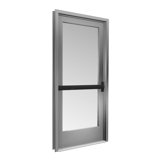
Summary of Contents for CRL JACKSON 2086
- Page 1 INSTALLATION INSTRUCTIONS CRL JACKSON 2086 CONCEALED VERTICAL ROD PANIC EXIT DEVICE Phone: (800) 421-6144 • Fax: (866) 921-0531 crlaurence.com • usalum.com • crl-arch.com crlaurence.com 11M0263...
-
Page 2: Tools Required
CRL JACKSON PANIC EXIT DEVICES - 2086 CONCEALED VERTICAL ROD ORDER OF ASSEMBLY AND INSTALLATION PARTS IDENTIFICATION 03 - 04 � � � � � � � � � � � � � � � � � � � � � � � � � � � � � � � � � � � � � � � � � � � � � � � � � � � � � � � � � � � � � � � � � � � � � � � � � � � �... -
Page 3: Parts Identification
CRL JACKSON PANIC EXIT DEVICES - 2086 CONCEALED VERTICAL ROD PARTS IDENTIFICATION FASTENERS PROVIDED USED WITH CALL FASTENER PART NUMBER QTY. FASTENER PART DESCRIPTION AND DESCRIPTION 1/4"-20 x 1/4" 302617 and 302619 Shoulder Stud Active Head Assembly Screws 1/4"-20 x 1/4"... - Page 4 CRL JACKSON PANIC EXIT DEVICES - 2086 CONCEALED VERTICAL ROD PARTS IDENTIFICATION PARTS LIST CALL PART PART NO. DESCRIPTION Optional 1" Single DL2170 Mortise Cylinder Actuator Link included in 2086 30799 Active Head Assembly Hardware Package 302607 30915J Rod and Case Assembly - 7/0...
-
Page 5: Door Preparation
CRL JACKSON PANIC EXIT DEVICES - 2086 CONCEALED VERTICAL ROD DOOR PREPARATION REMOVE DOOR AND PREPARE PER TEMPLATE 1. Place the door horizontally on the stands interior side up. 2. Mark the stile centerlines 1-1/8" (28.6) from the inside edge. (Fig. 1) 3. - Page 6 CRL JACKSON PANIC EXIT DEVICES - 2086 CONCEALED VERTICAL ROD DOOR PREPARATION – LAYOUT SELECTION 2086 EXIT DEVICE INSTALLATION - ACTIVE STILE INTERIOR VIEW 2086 Active Side ACTIVE STILE Mounting Inside Face 10-952 Drill and Tap for a 1/4"-20 Machine Screw...
- Page 7 CRL JACKSON PANIC EXIT DEVICES - 2086 CONCEALED VERTICAL ROD DOOR PREPARATION – LAYOUT SELECTION 2086 EXIT DEVICE INSTALLATION - INACTIVE STILE INTERIOR VIEW 2086 Inactive Side INACTIVE STILE Mounting Inside Face 10-952 Drill and Tap for a 1/4"-20 Machine Screw Use Template from Box FIG.
- Page 8 CRL JACKSON PANIC EXIT DEVICES - 2086 CONCEALED VERTICAL ROD DOOR PREPARATION – LAYOUT SELECTION 2086 EXIT DEVICE INSTALLATION WITH LOCK CYLINDER AND MOUNTING PAD INTERIOR VIEW ACTIVE STILE Drill and Tap for a 1/4"-20 Machine Screw (2) Places Drill and Counter...
- Page 9 CRL JACKSON PANIC EXIT DEVICES - 2086 CONCEALED VERTICAL ROD DOOR PREPARATION – LAYOUT SELECTION 2086 EXIT DEVICE INSTALLATION WITH EXTERIOR LOCKING LEVER TRIM INTERIOR VIEW INACTIVE STILE Drill and Counter Sink for a 10-24 FHMS (2) Places Drill and Tap for a 1/4"-20...
- Page 10 CRL JACKSON PANIC EXIT DEVICES - 2086 CONCEALED VERTICAL ROD DOOR HARDWARE INSTALLATION (CONTINUED) INSERT ROD AND CASE Insert the panic device rod and case assembly into ACTIVE STILE active stile (Fig. 9)� Align actuator pin through the slotted cut-out on interior face of stile, fastening with (2) 1/4"-20 x 1/4"...
- Page 11 CRL JACKSON PANIC EXIT DEVICES - 2086 CONCEALED VERTICAL ROD DOOR HARDWARE INSTALLATION (CONTINUED) INSTALL OPTIONAL MORTISE CYLINDER LOCK AND MOUNTING PAD NOTE: Lock and Mounting Pad must be installed before attaching exit device. 1� Attach the Mortise Cylinder Lock to the Mounting Pad and secure it with the Lock Ring, using (2) #8 x 2"...
- Page 12 CRL JACKSON PANIC EXIT DEVICES - 2086 CONCEALED VERTICAL ROD DOOR HARDWARE INSTALLATION (CONTINUED) INSTALL OPTIONAL LOCKING LEVER EXTERIOR TRIM NOTE: Exterior trim must be installed before attaching exit device. 1. Attach the exterior trim to the active stile with (2) #10 x 2-1/8"...
- Page 13 CRL JACKSON PANIC EXIT DEVICES - 2086 CONCEALED VERTICAL ROD DOOR HARDWARE INSTALLATION (CONTINUED) INSTALL 2086 EXIT DEVICE 1� Install the exit device on the door stiles assuring the actuator link engages the actuator pin. (Fig. 14) 2� Tighten (3) set screws on each side of the door stiles. (Fig. 15) 1/4"-20 x 5/16"...
- Page 14 CRL JACKSON PANIC EXIT DEVICES - 2086 CONCEALED VERTICAL ROD DOOR HARDWARE INSTALLATION (CONTINUED) OPERATIONS CHECK AND DOGGING INSTRUCTIONS OPERATIONS CHECK: 1� Depress the push bar to assure free movement of the rod and case assembly. Both upper and bottom bolts should activate to the open position.
-
Page 15: Frame Preparation
CRL JACKSON PANIC EXIT DEVICES - 2086 CONCEALED VERTICAL ROD FRAME PREPARATION RE-ATTACH DOOR TO FRAME 1. Make sure that the panic exit device is in the dogged position. Both the upper and bottom latches must clear the frame. Re-attach the door to the frame (Fig. 17). - Page 16 CRL JACKSON PANIC EXIT DEVICES - 2086 CONCEALED VERTICAL ROD FRAME PREPARATION (CONTINUED) ATTACH UPPER STRIKE 1. Drill and tap for (2) 10-32 x 3/8" FHMS on the mark made in step 2 of the frame preparation on page 16.
- Page 17 CRL JACKSON PANIC EXIT DEVICES - 2086 CONCEALED VERTICAL ROD DOOR HARDWARE ADJUSTMENTS UPPER BOLT: 1. The door must be in the closed position and the push bar must be in the un-dogged position to complete the following adjustments. 2. Depress the push bar, The bottom and upper rods will retract. With the rods in this position adjust the bottom bolt using the adjustment wrench included.
- Page 18 CRL JACKSON PANIC EXIT DEVICES - 2086 CONCEALED VERTICAL ROD PACKAGED PARTS AVAILABLE Cylinder Dogging Hardware Package Cylinder (Not Supplied) Spacer Ring 1/8" Collar for 1-1/8" Cylinder Cylinder lock Spacer Cylinder lock Cylinder Cam Assembly Assem. Assem. Part No. Description Part No.


Need help?
Do you have a question about the 2086 and is the answer not in the manual?
Questions and answers