Table of Contents
Advertisement
Advertisement
Table of Contents

Summary of Contents for Minikol M15S
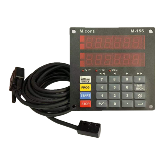
- Page 1 M15S OPERATION MANUAL minikol ITALY www.minikol.com...
-
Page 2: Table Of Contents
Index 1. Operation overview and general introduction............1 2. Operation Modes ....................2 2.1. Manual mode ....................2 2.2. Single mode....................3 2.2.1. Setting target value................3 2.2.2. Start / Stop / Cancel ................3 3. Fast Program (10 sets) ..................5 3.1. Entering preset target values ................5 3.2. - Page 3 24. Calibration......................26 25. Power supply & Hardware ................. 27 26. Troubleshooting ....................28 27.External Dimension..................... 30 28. Appendix A -- M15 Specifications ............... 31 29. Appendix B -- Parameter..................32...
-
Page 4: Operation Overview And General Introduction
1. Operation overview and general introduction 1.1 Front panel minikol Target value window Real value window Manual Single PROG INCH START STOP 1 / 32 MBE059F03... -
Page 5: Operation Modes
2. Operation Modes There are two base operating modes – MANUAL and SINGLE. In MANUAL mode: The operator can move the machine using the M15 keyboard. In SINGLE mode: Automatic positioning is performed. MANUAL 。 Press to select Manual mode or Single mode SINGLE MANUAL ※... -
Page 6: Single Mode
2.2. Single mode In single mode, the device performs automatic positioning of the machine to the programmed target position. 2.2.1. Setting target value Step 1 : Press PROG (Target window LED starts blinking) Step 2 : Enter the target value using numerical keypad; Step 3 : Press to complete . - Page 7 2.3. Example: Assume: actual target value on display = 100.00mm; actual real value on display = 100.00mm To change the target value to 20.25mm Step 1 : Press the LED lamp on Target window is blinking. PROG 10000 Display Target value 10000...
-
Page 8: Fast Program (10 Sets)
3. Fast Program (10 sets) To facilitate frequently used positions, the keys 0 to 9 have associated preset target values. By pressing one of these keys, its target value is loaded automatically, and the positioning can be started immediately. 3.1. Entering preset target values Step 1: Press Step 2: Select a key 0-9 (total of 10 values). -
Page 9: Execute
Step 6: Press ..…….…………………….【enter value】 Step 7: Press …………………….………………..【complete】 Step 8: Press to exit 3.2. Execute MANUAL Step1: Enter single mode, LED lamp is off. SINGLE Step2: Press a key 0-9 LED lamp is blinking -> ready for start . ※... -
Page 10: Select Counting Direction (+/-)
4. Select counting direction (+/-) You can select the counting direction according to the machine movement. Step 1: Press - dir Display ………………【default】 Setp 2: Press to change the direction, "-dir" for left or "dir- " PROG for right. Step 3: Press to confirm or press to clear. -
Page 11: Select Speed Mode
6. Select Speed Mode With this function, you can enter 1 speed mode or 2 speed mode. Step 1: Press SPEEd Display 1 SP 【default】 ……… Step 2: to switch between 1 or 2 speed. PROG Step 3: Press to confirm or press to clear. -
Page 12: Set Retract Distance
7. Set Retract Distance In some cutting application, you can retract the machine with a specified distance. Step 1: Press Display rEtr 5.00 Step 2: Enter the value (Min. = 0.01 , Max. = 20 ) Step 3: Press to confirm or press to clear. -
Page 13: Set Pulse/Rev Input From Conveyer
9. Set Pulse/Rev Input from Conveyer Get the real belt speed (M/min), please enter the pulse / rev input from conveyer according to each machine. To set the PPR of conveyer. Step 1: Press Display PPr 04.00 ………【default】 Step 2: Enter the value (PPR) to the real value window. Step 3: Press to confirm or press to clear. -
Page 14: Set Tolerance
11. Set Tolerance The tolerance defines the accuracy of the positioning. Step 1: Press Display toll 0.30 ……….【default】 Step2: Enter the value for tolerance. Step 3: Press to confirm or press to clear. 11 / 32 MBE059F03... -
Page 15: Set Low Speed Limit
12. Set Low Speed Limit This function defines the speed level which is considered abnormal for the machine. When M15 starts the movement in any direction, and the machine does not move, or moves with a speed lower than defined, it stops the machine and displays: EnGinE... -
Page 16: Set Linear Correction
13. Set Linear Correction Step 1: Press Display linCor 1.00000 Step 2: Please enter the value between 0.0001~9.9999 Step 3: Press to confirm or press to clear. 13 / 32 MBE059F03... -
Page 17: Enter Parameter Setting Mode
14. Enter Parameter Setting Mode With this function you can select each parameter to be locked or unlocked. When a parameter is locked, then the enduser can only see the value, but can not change it. Step 1: Press Display ☼... -
Page 18: Check Software Version
15. Check Software Version To check the released version of M15, you can: Step 1: Press Display SourCE AC-1.00 In the real value window, you will see the relased version. Step 2: Press to confirm or press to clear. 15 / 32 MBE059F03... -
Page 19: Load Datum Values
16. Load datum values The real position in the device is referred to the distance between the machine table and the cutting edge of the tool – in other words, the cutting edge of the tool defines the zero point of the machine. It is, however, difficult, or impossible to move the machine table to this point. -
Page 20: Example
16.3 Example The current value is 10.00mm but the actual length is 10.50mm. Step 1: Press Display OriGin 000 Step 2: Press Step 3: Press Step 4: Press 17 / 32 MBE059F03... -
Page 21: Presetting Tool Radius – 10 Sets
17. Presetting tool radius – 10 sets This function allows the operator to use up to 10 different tools on the same machine without the need to adjust the real value after tool change. Different tools normally have different radiuses. The effect of this is the zero point of the machine is shifted. -
Page 22: Example For Tool Setting
17.3. Example for Tool setting: Tool# 1 =10mm; Tool# 2 = 20mm . Step 1: Press Display OFFS Step 2: Press ………………….…………【select the tool# 1】 Step 3: Press ..…….………..【input the tool radius】 Step 4: Press ………………………………………【complete】 Step 5: Press …………………….………【select the tool#: 2】 Step 6: Press ..…………….【enter the tool radius】... -
Page 23: Example To Execute
17.4. Example to execute Call the tool#: 2 ( the tool radius is 20mm) . Step 1: Press LOAd 0 Display 000 Step 2: Press ……………..………..……..【Select the tool#: 2】 Step 3: Press ……………….………………..……【complete】 20 / 32 MBE059F03... -
Page 24: Fine Adjustment
18. Fine adjustment MANUAL ※ Only in single mode - LED lamp is off. SINGLE To set the step for fine adjustment. Step 1: Press Display StEP 1.00 ………...【default】 Step 2: Enter the value. Step 3: Press to confirm or press to clear. -
Page 25: Check Belt Speed
19. Check belt speed MANUAL ※ In single mode - LED lamp is off. SINGLE Press once . The PRM LED lamp turns on and the target window will show the belt speed. Press to exit . 20. IN/MM Conversion The dedicated MM/INCH key allows for immediate switch of the units between millimeters and inches. -
Page 26: Installation Guide
21. Installation Guide 21.1. The Magnetic Tape ★ The magnetic tape consists of three components Sensor side 1,8mm Mounting side 10mm A. A magnetized, highly flexible synthetic tape. B. Flexible steel tape. A and B are already factory-bonded. C. To keep the flexibility for transport and installation, the third part, also a steel tape is delivered separately. -
Page 27: Installation
21.2. Installation A. Ensure to apply tape on clean, dry and plain surface. B. For the best adhesion, please apply the tape with ambient temperature: 21~38℃. C. We recommend to make a chamfer on the machine to install the tape. +/- 3 <... -
Page 28: Set Device Resolution
22. Set Device Resolution Step 1: Press Step 2: Use to select resolution Step 3: Press to confirm or press to clear. 23. Change Counting Direction Step 1: Press Step 2: Press to change the direction PROG Step 3: Press to confirm or press to clear. -
Page 29: Calibration
24. Calibration Step 1: Press Go‧‧‧‧ Display Step2: Use to move the machine until M15 terminates the calibration and restarts. 26 / 32 MBE059F03... -
Page 30: Power Supply & Hardware
25. Power supply & Hardware a. Power supply: DC18 ~30V 50mA, 2 pin connector b. Battery: C type battery x 1, the battery life : 2.5 year (24hr) c. Output (8 pin connector) Relay × 4: Forward, Reverse, low speed and positioning. ※Positioning: only works inside the tolerance and on position mode. -
Page 31: Troubleshooting
26. Troubleshooting 26.1 Display CHAnGE rSt "Change RST" message appears when M15 detects a motion in the wrong direction. For example: M15 swtiches the outputs to move forward, but the bed starts moving in the reverse direction. Usually this is caused by the wrong wiring of the three phase motor. Press to clear. - Page 32 26.4 Display CHAnGE bAtt This message appears after power-on and indicates battery discharged. The battery MUST be changed to resume the operation of the device. The battery can be changed like this: - With power-on, change the battery. Then turn the power off, wait several seconds, and turn the power on again.
-
Page 33: External Dimension
27. External Dimension Unit: mm Battery Ø 5 x 4P Panel cut out : Required extra space for installation: 60mm (cable and connector) 30 / 32 MBE059F03... -
Page 34: Appendix A -- M15 Specifications
28. Appendix A -- M15 Specifications Feature Technical data Additional information 115w × 115h × 73d (mm) Housing 93w × 108h (mm) Panel cut out M3 × 4 Mounting screws 104 × 104 (mm) C type battery × 1 Supply voltage 24 VDC 50mA Battery voltage control Low power alarm via display... -
Page 35: Appendix B
29. Appendix B -- Parameter Parameter Display Description Default Remarks CHAnGE Load datum value Select counting direction (+ / -) -dir OriGin Load origin 0.00mm OffS- Set tool diameter 0.00mm POSdir Positioning mode ─ ─ ┤├─ ─ SPEEd One or two speed positioning rEtr Retract distance 5.00mm...
Need help?
Do you have a question about the M15S and is the answer not in the manual?
Questions and answers