Sign In
Upload
Download
Table of Contents
Contents
Add to my manuals
Delete from my manuals
Share
URL of this page:
HTML Link:
Bookmark this page
Add
Manual will be automatically added to "My Manuals"
Print this page
×
Bookmark added
×
Added to my manuals
Manuals
Brands
RainFlo Manuals
Water Pump
MHP75A
User manual
RainFlo MHP75A User Manual
Hide thumbs
1
2
3
4
5
6
7
8
9
10
11
12
Table Of Contents
13
page
of
13
Go
/
13
Contents
Table of Contents
Troubleshooting
Bookmarks
Table of Contents
Operation Conditions
Installation
Electrical Connection
Maintenance
Troubleshooting
Important Notice
Pressure Gauge
Construction Characteristics
Specifications
Installation Illustrations
Advertisement
Quick Links
1
Troubleshooting
Download this manual
®
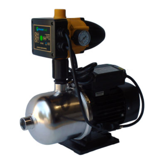
MHP75A / MHP150A
User Manual
It is the installer's responsibility to read, understand, and comply with these instructions.
Table of
Contents
Previous
Page
Next
Page
1
2
3
4
5
Advertisement
Table of Contents
Need help?
Do you have a question about the MHP75A and is the answer not in the manual?
Ask a question
Questions and answers
Related Manuals for RainFlo MHP75A
Water Pump RainFlo MHP150A User Manual
(13 pages)
Water Pump RainFlo MHP50 User Manual
(12 pages)
Water Pump RainFlo MHP75 User Manual
(12 pages)
Water Pump RainFlo 36667 User Manual
12v/24 diaphragm pumps (12 pages)
This manual is also suitable for:
Mhp150a
Table of Contents
Print
Rename the bookmark
Delete bookmark?
Delete from my manuals?
Login
Sign In
OR
Sign in with Facebook
Sign in with Google
Upload manual
Upload from disk
Upload from URL


Need help?
Do you have a question about the MHP75A and is the answer not in the manual?
Questions and answers