Table of Contents
Advertisement
Quick Links
See also:
User Manual
Advertisement
Table of Contents

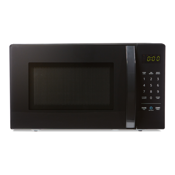
Summary of Contents for AmazonBasics S9N29R
- Page 1 MICROWAVE OVEN SERVICE MANUAL Model: S9N29R CAUTION: BEFORE SERVICING THE UNIT, READ SAFETY PRECAUTIONS IN THIS MANUAL...
-
Page 2: Table Of Contents
SAFETY PRECAUTIONS CONTENTS This device is to be serviced only by properly qualified service personnel. SAFETY PRECAUTIONS Consult this service manual for proper service procedures to ensure continued CAUTION ....................safe operation and for precautions to be taken to avoid possible exposure to INSTALLATION .................. -
Page 3: Caution
CAUTION INSTALLATION Unlike other appliances, the microwave oven is MICROWAVE RADIATION BEFORE YOU BEGIN, READ THE FOLLOWING INSTRUCTIONS a high-voltage, high-current device. Though it is Personnel should NOT be exposed to microwave COMPLETELY AND CAREFULLY. free from danger in ordinary use, extreme care energy that may radiate from the magnetron should be taken during repair. -
Page 4: Service Information
SERVICE INFORMATION CIRCUIT DESCRIPTION TOOLS AND MEASURING INSTRUMENTS • A high voltage of approximately 2100 VAC is GENERAL DETAILS NECESSARY TOOLS NECESSARY MEASURING generated in the secondary of the high-voltage • The low voltage transformer supplies the Tools normally used for TV servicing are INSTRUMENTS transformer which is increased by the action necessary voltage to the micom controller... -
Page 5: Disassembly And Adjustment
DISASSEMBLY AND ADJUSTMENT MEASUREMENT WITH OUTER NOTES WHEN MEASURING • Do not exceed the meter’s full-scale deflection. CASE REMOVED 1. OUTER CASE REMOVAL 4. DOOR ASSEMBLY REMOVAL • When you replace the magnetron, measure • The test probe must be moved no faster than for microwave energy leakage before the 1 in/second (2.5 cm/second) along the shaded •... -
Page 6: Door Assembly Removal
5. HIGH-VOLTAGE 8. MAGNETRON REMOVAL 9. REMOVING THE 10. PCB ASSEMBLY REMOVAL • Disconnect the leadwire from the high-voltage • Remove the control panel assembly from TRANSFORMER REMOVAL TURNTABLE MOTOR transformer and high-voltage capacitor. the cavity. • Discharge the high-voltage capacitor. •... -
Page 7: Interlock System
INTERLOCK CONTINUITY TEST 11. INTERLOCK SYSTEM C. INSTALLATION AND ADJUSTMENT OF THE LATCH BOARD TO THE OVEN ASSEMBLY A. INTERLOCK MECHANISM WARNING: FOR CONTINUED PROTECTION AGAINST • Mount the latch board to the oven assembly. The door lock mechanism has been specially EXCESSIVE RADIATION EMISSION, REPLACE ONLY WITH designed to eliminate completely microwave •... -
Page 8: Component Test Procedure
COMPONENT TEST PROCEDURE CAUTIONS: COMPONENTS TEST PROCEDURE RESULTS A. DISCONNECT THE POWER SUPPLY CORD FROM THE OUTLET WHENEVER REMOVING THE OUTER CASE FROM THE UNIT. PROCEED WITH THE TEST ONLY AFTER DISCHARGING THE Antenna HIGH-VOLTAGE CAPACITOR AND REMOVING THE WIRE LEADS FROM THE PRIMARY WINDING Gasket OF THE HIGH-VOLTAGE TRANSFORMER. - Page 9 COMPONENTS TEST PROCEDURE RESULTS COMPONENTS TEST PROCEDURE RESULTS Check for PCB connector. L.V.Transformer of PCB Normal Abnormal Check for continuity of the fuse with a Normal Abnormal F US E multi-meter. (Refer to schematic diagram) NOTE: Disconnect the 3 pin connector from PCB.
-
Page 10: Troubleshooting
TROUBLESHOOTING TROUBLE 1 The following visual conditions indicate a control circuit that may be defective. 1. Incomplete segments of digital clock and/or timer display. WHEN YOU GET A COMPLAINT FROM YOUR CUSTOMER, EVALUATE THE COMPLAINT CAREFULLY. • Segment missing. IF THE FOLLOWING SYMPTOMS APPLY, PLEASE INSTRUCT THE CUSTOMER IN THE PROPER USE OF •... - Page 11 TROUBLE 2 TROUBLE 3 Oven does not operate at all. Display window does not display any figures and no input Display shows all figures set, but oven does not start cooking while desired program times are is accepted. set and START pad is touched. CONDITION CHECK RESUL T...
- Page 12 TROUBLE 5 TROUBLE 6 No microwave oscillation even though oven lamp and fan motor run (Display Oven does not cook properly when programmed for the set power level (Operates properly operates properly). on HIGH). CONDITION CHECK RESULT CAUSE REMEDY CONDITION CHECK RESULT CAUSE...
-
Page 13: Exploded View And Spare Parts List
EXPLODED VIEW AND SPARE PARTS LIST WIRING DIAGRAM PN:16170000A65421 ©2018 Amazon.com, Inc. or its affiliates. Amazon and all related logos are trademarks of Amazon.com, Inc. or its affiliates.


Need help?
Do you have a question about the S9N29R and is the answer not in the manual?
Questions and answers