Advertisement
NSB²
Operation Manual
Read these instructions for the proper use of this machine.
After having read these instructions,
keep them in a convenient place so you
or the operator can refer to them whenever necessary.
ATTENTION : www.ohtake-root.co.jp is the only web site associated with our company.
We do not have any branches in China.
www.ohtake-root.co.jp
www.ohtake-root.co.jp
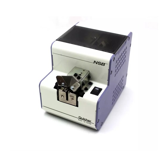
Automatic Screw Feeder
Series
(Maintenance)
HP
自動ネジ供給機
NSB2MA01 Ma
Advertisement

Summary of Contents for OHTAKE NSB2 Series
- Page 1 After having read these instructions, keep them in a convenient place so you or the operator can refer to them whenever necessary. ATTENTION : www.ohtake-root.co.jp is the only web site associated with our company. We do not have any branches in China. www.ohtake-root.co.jp www.ohtake-root.co.jp...
-
Page 2: Table Of Contents
CONTENTS 1. BEFORE USE ・・・・・・・・・・・・・・・・・・・・・・・・・・・・・・・・・・ 2. FOR SAFE USE ・・・・・・・・・・・・・・・・・・・・・・・・・・・・・・・・・・ 3. NAME OF MACHINE PARTS・・・・・・・・・・・・・・・・・・・・・・・・・・・・・・・・ 4. ADJUSTMENTS AND CHECKS BEFORE USE ・・・・・・・・・・・・・・・・ 5. OPERATING INSTRUCTIONS・・・・・・・・・・・・・・・・・・・・・・・・・・・・・・・ 6. REPLACEMENT OF CONSUMABLE PARTS ・・・・・・・・・・・・・・・・・ 7. OTHERS ・・・・・・・・・・・・・・・・・・・・・・・・・・・・・・・・・・ 8. TROUBLESHOOTING ・・・・・・・・・・・・・・・・・・・・・・・・・・・・・・・・・・ 9. SPECIFICATIONS ・・・・・・・・・・・・・・・・・・・・・・・・・・・・・・・・・・ 10. -
Page 3: For Safe Use
FOR SAFE USE 2) Read the following Cautions thoroughly for the safe use of this machine. Keep them in mind during the operation of the machine in order to prevent injuries and damage to property. - Installation Caution: Install the machine on a level, stable location that can endure it’s weight and running conditions. If the machine falls down or turns over due to improper installation, injuries or property damage may occur. -
Page 4: Name Of Machine Parts
3) NAMES OF MACHINE PARTS Scooping chamber Passing plate identification seal Scooping block Upper cover (left and right) Passing plate Rail fixing bolt (moving up and down) Rear cover Bit guide Power swtich Light-receiving sensor Brush Timer knob DC jack Tilting bolt(under the machine) Tilting bolt(under... - Page 5 4) ADJUSTMENTS AND CHECKS BEFORE USE Before using the machine, please check if the rail and components installed on the machine is suitable for the screw ap- plied. The rail is φ 1.0 to φ3.0 depending on the nominal diameter. It is determined by the identification seal on a rail front cover.
- Page 6 ◆ Adjustment of the brush Check the height of the brush. * As in the picture on the right, set the brush to an approxi- Turn the power switch on & off, mately level position. and set the brush on the level. * Ensure that the edge of the brush is grazing the screw’s head.
- Page 7 ◆ Adjustment of the holding plate Holding plate Check the position of the holding plate. * Ensure that the gap between the head of the used screw in the rail Screws groove and the holding plate is approximately 0.2 mm to 1 mm. * If there is no gap, the screw gets caught.
- Page 8 ◆ Adjustment of the passage plate Passage plate Check the height of the passage plate. Passage plate * Ensure that the passage plate is adjusted at a height where the attaching screw used screw can manage to pass. Halfway hole * If the passage plate is too low, the screw cannot pass, and if too (On both sides of the passage plate) high, the screw easily gets caught.
- Page 9 Check/adjustment of the bit guide ◆ The bit guide attaching screws (Assy. attachiing Check the position of the bit guide. screws) * Adjust the bit guide to a position where a user can easily take screws. Actually pick up screws a few times to adjust it. Adjustment Adjust it by loosening the attaching screws.
- Page 10 ◆ Check/adjustment of rail vibration Transfer speeds of screws differ according to screw type. Amplitude This machine can change rail amplitude and adjust the transfer speed. fixing screw * To adjust amplitude, loosen an amplitude fixing screw at the rear of this machine and turn the amplitude adjusting screw at the bottom of Amplitude (Vibration)
- Page 11 ◆ Check of the sensor’s optical axis If there is no screw at the stopper section, this machine continues operation, and if there are screws, it stops after a certain period of time has passed. This machine has the level of the screw/no screw sensor adjusted by the reference rail on shipment.
- Page 12 ◆ Adjustment and Check of the timer he speed of screw delivery depends on the actual kind of screw. By adjust- ing the timer of the machine the screws are picked up smoothly. * If a screw is picked up on the stopper and the screw coming next is not Use the provided picked up for a certain amount of time, the unit stops the operation.
-
Page 13: Operating Instructions
OPERATING INSTRUCTIONS 5) ◆ Supplying screws (Refer to P. 4) * Set the [scooping block] to the lowest possible position. Remove the top cover of the [scooping chamber]. Throw in screws up to a position of 2 mm to 3 mm below the rail groove top face. * In this condition, ensure that the front inclined-face of the ramp is not hidden by the screws. -
Page 14: Replacement Of Consumable Parts
6) REPLACEMENT OF CONSUMABLE PARTS Remove the brush assembly attaching screw ◆ Replacement of brushes * If the tip of the brush wears out and does not wipe off a screw from an abnormal position, replace it with a new brush. * Turn the machine’s power switch on and off and position the brush as in the diagram on the right. - Page 15 ◆ Replacement of the bit guide unit Remove the bit guide. Replace the holding plate when there is difficulty in using it, such as after excessive wear. When replacing the holding plate, remove the bit guide section off the body to prevent a mounting screw from falling inside the body. * As in the diagram on the right, remove the bit guide section and replace the holding plate.
- Page 16 ◆ Replacement of the stopper Rail fixing screw Replace the stopper when there is difficulty in using it, such as after excessive wear. * As in the diagram on the right, loosen the rail fixing screws and pull out the rail from the body. Pull out the rail * The stopper can be changed as in the diagram on the right.
- Page 17 ◆ Replacement of the main motor unit Remove the cover Replace the motor after it is damaged. * Remove the cover from the body. (During removal, as in the diagram on the right, the cover mounting screws should be removed together with the front cover, leaving the four screws of the rear in place.) * Remove the motor trunk connector.
- Page 18 ◆ Movement timing when replacing a motor Drop [scooping block] on the right and left * To time a movement of the [scooping block] and that of a brush, as much as possible. the gears must be in mesh. The pin is * If only the motor section is removed from the body, the approximatwly movements can be timed by reassembling the motor section...
-
Page 19: 7) Others
7) OTHERS ◆ Eeternal output signals The jack on the back of the machine serves as the detection of picked screw up, which shall be used with external screw counters. [Function]: When picked screw up : signal high (ON) approx. 0.2sec Incoming current: shall be limited to less than 100mA **CAUTION: Additional resistor is required on external circuit for regulating current **... -
Page 20: Troubleshooting
TROUBLESHOOTING (Please check the following before asking for a repair.) 8) Caution: Unplug the AC adapter from the wall outlet before and while making any adjustments to avoid injury or machine malfunction. Trouble Cause Measures * Confirm the power supply connection * Power is not supplied. - Page 21 Trouble Cause Measures 7-2 * A shank of a screw is caught in the * Remove abnormal screws.Next, adjust Screws do not feed. passage plate. the passage plate. * Remove the screw in an abnormal * A screw has stopped in an abnormal position in the middle of the rail.
- Page 22 Trouble Cause Measures * The gap between the holding plate and * Adjust the bit guide assembly (together 7-4 the screw head is too small. with the holding plate). The screws on the rail are not feeding smoothly. * Screws with spring washer, of one * Run the machine on an incline.
- Page 23 Trouble Cause Measures A screw has stopped in an abnormal * Adjust the bit guide and holding plate. 7-6 position in the middle of the rail. The screws often run in an abnormal position through the * Adjust the Rail Assembly back and passage plate.
- Page 24 Trouble Cause Measures 7-9 * Shake off the screw from the hole on A screw has dropped inside the back of the machine. the machine. * There’s deviation of the rail and sensor * Move the rail back and forth and adjust 7-10...
-
Page 25: Specifications
[Caution] 9) SPECIFICATIONS - AC adapter which attaches to an old type NSB series can't be used. - Check if the axis diameter of the loaded screw corresponds with the Power Input:AC100~240V 50/60Hz below rail groove width. AC adapter - With the range of screw size and lengths below, there may be Output:DC15V 1A instances lf unique screw shape or stracture not com;atible with the (switching type)... - Page 26 Reference table of the specified screws Pan head Screw Screw Screw Screw Screw Passing plate Screw Screw shaft head head shaft Double feeder feeder Screw size Rail model No. Sems model No. size diameter(φ ) diameter thickness length sems series model (φ...
- Page 27 10) EXTERNAL DIMENSIONS Signal output jack Unit : mm - 26 -...
- Page 28 11) WARRANTY For users within Japan, the effective term of warranty is 6 months after delivery. Such warranty will not be applicable to purchases or users outside of Japan. If any troubles should occur, please contact your dealer. After the warranty period, repair services will be completed. In the following cases, the purchaser shall pay for parts and labor regardless of the terms of warranty: ①...
- Page 29 Fax +81-191-24-3145 Fax +81-191-24-3145 「Quicher」 「OHTAKE」 「OHTAKE ・ ROOT KOGYO」 are trademarks or/and registered trademarks of OHTAKE ・ ROOT KOGYO CO.LTD.] 「Quicher( クイッチャー)」 「OHTAKE」 「OHTAKE ・ ROOT KOGYO」 は、 株式会社 大武 ・ ルート工業の商標又は登録商標です。 The specifications and/or design may be altered, without notice, whenever there are changes or improvements.
Need help?
Do you have a question about the NSB2 Series and is the answer not in the manual?
Questions and answers