Table of Contents
Advertisement
C
M
L
C
M
L
M
M
M
e
d
i
M
e
d
i
Fields of use
MECHANICAL – HYDRAULIC – METAL FABRICATION – MARINE ENGINEERING
– ELECTRICAL GENERAL INSTALLATION
®
Ercolina
CML International S.p.A.
by
+39 0776 40281
+39 0776 40281
www.ercolina.it
info@ercolina.it
CML U.S.A. Inc.
8506 North Fairmount
Davenport Iowa 52806 (USA)
+1 563 391 7700
+1 563 391 7710
www.ercolina-usa.com
info@ercolina-usa.com
Art.070 User Guide EN
I
n
t
e
r
n
a
t
i
o
n
a
l
S
.
I
n
t
e
r
n
a
t
i
o
n
a
l
S
.
I
n
s
t
r
u
c
I
n
s
t
r
u
c
e
d
i
B
e
e
d
i
B
e
B
e
n
d
e
B
e
n
d
e
ITALY
CML DEUTSCHLAND GmbH
Grafenbergweg 11
73614 Schorndorf
+49 (0) 7181 87266
+49 (0) 7181 87298
www.ercolina.com
cml-deutschland@t-online.de
p
.
A
.
p
.
A
.
t
i
o
n
M
t
i
o
n
M
n
d
e
r
A
n
d
e
r
A
r
S
p
e
c
i
r
S
p
e
c
i
User Guide EN
Rev. 1.0.0
Date 04.23.2004
a
n
u
a
l
a
n
u
a
l
r
t
.
0
7
0
r
t
.
0
7
0
a
l
A
r
t
.
a
l
A
r
t
.
CML France S.a.r.l.
La Gare
10190 Villemaur sur Vanne (F)
+33 325 4081 04
+33 325 4081 13
www.ercolina.com
cmlfrance@wanadoo.fr
0
7
1
0
7
1
1
Advertisement
Table of Contents

Related Manuals for Ercolina Medi Bender

Summary of Contents for Ercolina Medi Bender
- Page 1 User Guide EN Rev. 1.0.0 Date 04.23.2004 Fields of use MECHANICAL – HYDRAULIC – METAL FABRICATION – MARINE ENGINEERING – ELECTRICAL GENERAL INSTALLATION ® Ercolina CML International S.p.A. ITALY +39 0776 40281 +39 0776 40281 www.ercolina.it info@ercolina.it CML U.S.A. Inc.
- Page 2 Distributed by: Trick-Tools 75 Truman Road Pella, IA 50219 Phone:1-877-VAN-SANT E-mail: sales@trick-tools.com Here at Trick Tools we believe that our customers deserve the best value in their tool and equipment purchases. We are constantly at work searching out a variety of high quality, high performance tools to offer at the best prices possible.
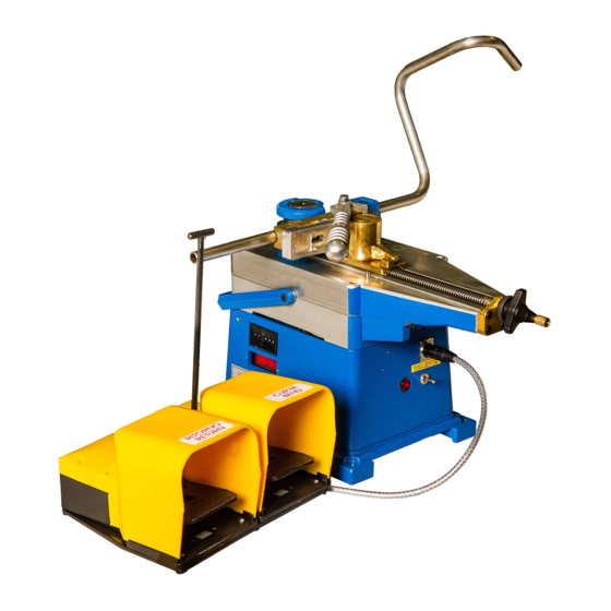
- Page 3 Phone: +39 776 404572 Fax: +39 776 404801 The Manufacturer is not liable for any damages due to the use of not original Ercolina® tooling Congratulations for the purchase of your Medi Bender. Observe the following instructions and your Medi Bender will become a simple and useful working tool.
-
Page 4: Table Of Contents
PROGRAMMING A BEND ON DIGITAL MODELS – ART. 070 AND 071 BENDING OPERATIONS WITH DIGITAL MODELS – ART. 070 AND 071 3.4.1 HOW TO REGAIN THE SPRING BACK ANGLE EXAMPLES OF CORRECT BENDING WITH THE MEDI BENDER MAINTENANCE HOW TO FIT THE SPECIAL HEXAGONAL SHAFT VICE ASSEMBLY (ACCESSORY) - Page 5 Tables TABLE 2.1.1 – PART IDENTIFICATION TABLE 2.2.1 – MACHINE CAPACITY TABLE 2.2.2 – HEXAGONAL SHAFT SPEED TABLE 2.2.3 – SUPPLY VOLTAGE TABLE2.2.4 – PROTECTION FUSES TABLE 2.2.5 – DIMENSIONS AND WEIGHT TABLE 3.4.1 – SPRING BACK ANGLE SETTING TABLE 3.7.2 – SPECIAL HEXAGONAL SHAFT Figures FIGURE 2.1.1 –...
-
Page 6: General Rules
SECTION I GENERAL RULES GENERAL SAFETY RULES Pay attention to this symbol; it indicates a possible dangerous situation Pay attention to this symbol; it indicates a forbidden action for the Operator/User Pay attention to this symbol; it indicates a mandatory action for the Operator/User MANDATORY Read carefully the before using the machine... -
Page 7: Terminology Used
1.1.1 TERMINOLOGY USED Some recurrent definitions are explained below: USER ERSON OR ODY OR OMPANY THAT HAS BOUGHT OR RENTED THE MACHINE AND THAT INTENDS TO USE IT ACCORDING TO ITS EXPECTED USE AND SCOPE MACHINE USE AND OPERATING PERSONNEL TRAINING IS HIS RESPONSIBILITY DANGEROUS AREA ANY AREA INSIDE AND... -
Page 8: General Warnings
1.1.2 GENERAL WARNINGS Read Carefully the before using the machine; MACHINE USE AND MAINTENANCE MANUAL The User must only assign the machine to specifically trained and qualified personnel; The User must take all the necessary measures to prevent unauthorized personnel from accessing the machine;... -
Page 9: General Instructions
The Manufacturer is not liable for damages to things or persons due to an improper machine use; Check that power supply observes the necessary voltage for the Medi Bender; Only assign qualified personnel to the machine; Do not use the machine in environments containing inflammable gas or fluids;... -
Page 10: Transportation
Check periodically the hexagon wearing; Only one person at a time must use the machine. 1.1.4 TRANSPORTATION WARNING BEFORE NG THE MACHINE TRANSPORT ♦ Unplug power supply; ♦ Disconnect the pedal switch; ♦ Remove all the accessories assembled on the machine. WARNING DURING MACHINE TRANSPORTATION ♦... -
Page 11: Technical Data
SECTION II TECHNICAL DATA 2.1 PART IDENTIFICATION Former Knob Counterbending die 10 Switch Swivelling bracket 11 Foot switch connection Counterbending die support 12 Fuse holder Tightening screw 13 Degree selector Lever 14 Display Stop 15 Overload led Reset ring 16 Handle Table 2.1.1 –... -
Page 12: Former
2.1.1 FORMER The information included in the former is: Figure 2.1.1 – Former Point of reference “0” for placing the former Tube diameter for which the former has been designed Former bending radius 2.1.2 COUNTERBENDING DIE The information stamped on the counterbending die is regarding the tube dimensions it was designed for. Art.070 User Guide EN... -
Page 13: Slider - Counterbending Die Unit
2.1.3 SLIDER – COUNTERBENDING DIE UNIT Slider-counterbending die unit elements are indicated in the following figure: Swivelling bracket Stop Reset ring Knob Lever Counterbending die tightening screw Counterbending die support Art.070 User Guide EN... -
Page 14: Technical Data
♦ Digital Medi Bender Art. 070; ♦ Digital Medi Bender Special Art. 071. 2.2.1 WORKING CAPACITY The machine can bend materials included in the table starting from a minimum diameter of 5 mm, with minimum radius depending on material used, diameter and thickness. -
Page 15: Machine Capacity
2.2.3 MACHINE CAPACITY The following table indicates the maximum bending capacity of the Digital Medi Bender Art. 070 and of the Digital Medi Bender Special Art. 071. The information reported below is approximate and may vary according to the material chemical composition. -
Page 16: Electrical Data
2.2.5 ELECTRICAL DATA Machines must be connected to the power supply it was intended for by design. Power supply: Voltage Frequency Power Current 220V 50/60Hz 1000W 110V 50/60Hz 1000W Table 2.2.3 – Supply Voltage Insulation level: 1 Motor: electrical motor with double insulation in conformity with EC standards Protection: protection system with fuses Model Fuse... -
Page 17: Machine Use
Bending radius: It must not be confused with the angle, it is measured from the tube center to the bending center The Ercolina system is able to correct the bending angle according to the material used 3.2 ACCESSORIES Formers and counterbending dies are made of aluminum and steel according to the material to bend. Ask your dealer. -
Page 18: Machine Turning-On
3.2.3 MACHINE TURNING-ON The machine turns on as soon as it is connected to a power supply (220 V or 110 V). Warning: Check that power supply voltage observes the machine design voltage before plugging it to the power supply. 3.2.4 MACHINE PREPARATION Insert the tube and prepare the swivelling bracket. -
Page 19: Figure 3.2.3 - Bracket Unit
Figure 3.2.3 – Bracket Unit 1 Counterbending die insertion handle Note: Press and rotate rightwards to hold. Rotate leftwards to losen counterbending die. 2 Attaching handle for slider set Note: Use the brass knob to speed up the approach 3 Reset ring Art.070 User Guide EN... -
Page 20: Programming A Bend On Digital Models - Art. 070 And 071
Spring back angle selector 3.4 BENDING OPERATIONS WITH DIGITAL MODELS – ART. 070 AND 071 NOTE. Only for Digital Medi Bender models Art. 070 and 071. The machine is now ready to bend. To bend observe the following instructions: a. Press the switch rightwards [Bend] or press the pedal [Bend]. The former will rotate and the tube will be bent to the angle value. -
Page 21: Table 3.4.1 - Spring Back Angle Setting
d. Continue the bending process by pressing the bend/return switch rightwards [Bend]. As soon as the bend will be completed the machine will automatically stop and the display will show the bent angle value and the spring back angle (the selected values will be kept in memory even if the machine is turned off). -
Page 22: Examples Of Correct Bending With The Medi Bender
3.5 EXAMPLES OF CORRECT BENDING WITH THE MEDI BENDER Counterbending die Roll Reinforcement bracket Note: Only for the roll use! Rotate the former approximately 30°. Insert the tube. Place the roll on the tube without forcing and then bend. Art.070 User Guide EN... -
Page 23: Maintenance
3.6 MAINTENANCE Digital Medi Bender – Art. 070 Digital Medi Bender Special – Art. 071 Ordinary Maintenance: Grease the machine gear box with a greasing pump every 24 working hours. Extraordinary Maintenance: Control brush wearing every 800 working hours or at least every 6 months. In case of wear use exclusively spare parts supplied by the manufacturer when replacing them. -
Page 24: How To Fit The Special Hexagonal Shaft
3.7 HOW TO FIT THE SPECIAL HEXAGONAL SHAFT The special hexagonal shaft installation is only for the machine Art. 070. Note: Small 10mm to 35mm.radius formers can be inserted by removing the shaft. Art.070 User Guide EN... -
Page 25: Vice Assembly (Accessory)
3.8 VICE ASSEMBLY (ACCESSORY) To insert the vice: loosen the 5 screws and extract the bracket unit to insert the vice Art. 087. Art.070 User Guide EN... -
Page 26: Spacer For Special Radius
3.9 SPACER FOR SPECIAL RADIUS The optional spacer must be used to perform bends with special radius (from R = 130mm to R = 180mm max). Loosen the 5 screws M6x55, insert the spacer and re-tighten the knob unit. Art.070 User Guide EN... -
Page 27: Appendixes
SECTION IV APPENDIXES 4.1 APPENDIX 1 MACHINE OPERATION TROUBLESHOOTING Note: where not otherwise specified, defects and solutions are valid for all machine models (art. 070 and 071) PROBLEM CAUSE SOLUTION The machine does not switch on Electrical connection Check plug The machine does not switch on Electrical connection Check electrical wire... -
Page 28: Appendix
5. Former and counterbending die must never touch each other because the tube may break and the machine may get damaged. 6. Use the special Ercolina grease spray to avoid excessive friction of parts in motion and to improve results. - Page 29 Tube with chemical characteristics Try bending using the special tube because of its chemical exceeding machine capacity Ercolina® roll composition and it is overloaded For any other technical problem regarding bending operations contact your Ercolina® dealer. Art.070 User Guide EN...
-
Page 30: Appendix
4.4 APPENDIX 4 ELECTRICAL DIAGRAM Overload led Speed switching Digital Medi micro Bender (Art. 070 and Art To motor 071) Electrical connection diagram. Supply Digital counter card type B4. Main Fuse (8 Amps max) Electronic Card (P114 A1) Type B3/2 = 220 V Earth Type B3/1 = 100. - Page 31 DATABASE ELASTICITY DEGREE TUBE TYPE Φ BENDING RADIUS WALL OR SPRING BACK Notes Art.070 User Guide EN...
- Page 32 DATABASE ELASTICITY DEGREE TUBE TYPE Φ BENDING RADIUS WALL OR SPRING BACK Notes Art.070 User Guide EN...
- Page 33 DATABASE ELASTICITY DEGREE TUBE TYPE Φ BENDING RADIUS WALL OR SPRING BACK Notes Art.070 User Guide EN...
- Page 34 DATABASE ELASTICITY DEGREE TUBE TYPE Φ BENDING RADIUS WALL OR SPRING BACK Notes Art.070 User Guide EN...
- Page 35 DATABASE ELASTICITY DEGREE TUBE TYPE Φ BENDING RADIUS WALL OR SPRING BACK Notes Art.070 User Guide EN...
- Page 36 Notes Notes Art.070 User Guide EN...
- Page 37 Notes Art.070 User Guide EN...
- Page 38 Notes Notes Art.070 User Guide EN...
- Page 39 Notes Art.070 User Guide EN...
- Page 40 Notes Notes Art.070 User Guide EN...
- Page 41 Art.070 User Guide EN...
Need help?
Do you have a question about the Medi Bender and is the answer not in the manual?
Questions and answers