Table of Contents
Advertisement
Advertisement
Table of Contents

Related Manuals for Conergy IPG Series


Summary of Contents for Conergy IPG Series
- Page 1 Conergy IPG string inverter series Operating manual...
-
Page 2: Table Of Contents
T a b le o f c o n t e n t s T a b le o f c o n t e n t s In t r o d u c t io n Short description Additional products User group Signposts... - Page 3 In s t a lla t io n a n d c o m m is s io n in g Basic safety instructions Preparation for installation Connections Connecting the mains cable Connecting the solar system Connecting the Conergy SunReader: Connecting the 230- V power supply Connecting Easyconnect Connecting further string inverters 6.10 Connecting the terminator 6.11...
-
Page 4: In T R O D U C T Io N
5,000 Wp. The string inverters belong to the Conergy IPG string inverter series product group, which in turn is part of the Conergy IPG series (IPG = Inverter Power on Grid). C o n e r g y IP G s t r in g in v e r t e r s e r ie s... -
Page 5: Additional Products
1 In t r o d u c t io n Additional products String inverters of the Conergy IPG series can optimally be used with the Conergy IPG easyconnect generator junction box. These devices are designed to work together and allow for simple, time-saving installation. -
Page 6: Signposts
. Item numbers are shown in the form (1) and (2) . Display messages are shown in a di f f er ent f ont . The names of companies other than Conergy are shown in italics. Symbols Denotes the start of an operation with a description of its objective. -
Page 7: M Anufacturer Information
Conergy AG, 2006 Standards and technical directives The string inverters of the Conergy IPG string inverter series comply with the following standards and directives: | 89/336/EEC: Council Directive on the approximation of the laws of Member States relating to electromagnetic... - Page 8 1 In t r o d u c t io n | Electronic equipment for use in power installations (IEC 62103: 2003); German version EN 50178: 1997 | Safety of power converters for use in photovoltaic power systems – Part 1 – General requirements (IEC 62109-1: 2005) | Safety of power converters for use in photovoltaic power systems –...
- Page 9 1 In t r o d u c t io n In st ru c t io n m an u al C o n e r g y IP G s t r in g in v e r t e r s e r ie s...
-
Page 10: Sa F E T Y
2 S a f e t y S a f e t y Intended use String inverters of the Conergy IPG Series are designed exclusively for the conversion of direct current from solar modules to alternating current. Any other use is deemed not to be as intended. -
Page 11: Basic Safety Instructions
| Observe the warnings posted on the device itself. | You must immediately renew any warning signs fitted on the system which have become illegible. Where appropriate, inform Conergy Service. | If the inverter is opened, the warranty of the system is invalidated. -
Page 12: Warnings
2 S a f e t y Warnings Warning signs provide information relating to safety. They consist of the following: Warning symbol (pictograph), | Indicator word to denote the level of risk, | Details of the nature and source of the risk | Information on the possible consequences of disregarding the risk Instructions on what to do to avert the risk and prevent... - Page 13 2 S a f e t y In st ru c t io n m an uall C o n e r g y IP G s t r in g in v e r t e r s e r ie s...
-
Page 14: R O D U C T D E S C R Ip T Io N
3 P r o d u c t d e s c r ip t io n P r o d u c t d e s c r ip t io n General information on photovoltaic systems A grid-connected photovoltaic system essentially consists of the following components: | Solar power system (1) The solar power system consists of several photovoltaic... - Page 15 You can connect up to two photovoltaic module strings (photovoltaic modules connected in series) to each string inverter of the Conergy IPG series. If you wish to connect more strings, use the Multi-Contact branch connector plugs and sockets. Note the specifications on the string inverter (see chapter 9.1, page 57).
-
Page 16: Block Diagram
3 P r o d u c t d e s c r ip t io n AC disconnect (5) It must be possible to disconnect the AC supply from the grid (on the AC side) by means of a disconnector. This is a prerequisite for ensuring the absence of current to the unit, e.g. - Page 17 For this reason, the string inverters of the Conergy IPG series monitor the public power grid by means of the phase-shifting process. Every string inverter has the following data interfaces: | CTRL...
-
Page 18: Functions
3 P r o d u c t d e s c r ip t io n Functions The core of each string inverter of the Conergy IPG series is formed by the patented Conergy Balanced Mode Technology (BMT) circuit concept. The circuit consists of a combination of Insulated Gate Bipolar Transistors (IGBT), diodes and chokes. - Page 19 Phase Shifting If there is a fault of the public power grid, each string inverter of the Conergy IPG series detects this fault on the basis of the change in frequency of the current. The frequency of the public grid is at 50 Hz (nominal frequency).
-
Page 20: O N E R G Y Ip G S T R In G V Is Io N In V E R T E R S E R Ie S
C o n e r g y IP G s t r in g v is io n in v e r t e r s e r ie s Every string inverter of the Conergy IPG string vision inverter series is equipped with a display. - Page 21 4 C o n e r g y IP G s t r in g v is io n in v e r t e r s e r ie s Language You can call up the display text in German, English, Italian or Spanish.
- Page 22 4 C o n e r g y IP G s t r in g v is io n in v e r t e r s e r ie s Fig. 4-1: Selecting the language Display You can call up updated data for today, the values from the previous day and photovoltaic system data for the last 7 days via the display.
- Page 23 4 C o n e r g y IP G s t r in g v is io n in v e r t e r s e r ie s Selecting the display type 1. Select the menu Set t i ngs by touching the appropriate area.
- Page 24 4 C o n e r g y IP G s t r in g v is io n in v e r t e r s e r ie s In the Di agnos t i c s submenu you will find fault messages and diagnostic information for the inverter.
- Page 25 4 C o n e r g y IP G s t r in g v is io n in v e r t e r s e r ie s Calibration You can calibrate the display. If you detect that the touch areas have moved, re-calibrate the display.
-
Page 26: Tr A N S P O R T A N D In S T A Lla T Io N
| Drill template | Wall bracket | Basic installation equipment | Warranty card | Instruction manual Conergy IPG string vision inverter series | 230 V power supply cable Transportation CAUTION! Damage due to improper transportation. When slewing and depositing the load, electronic equipment... -
Page 27: Installation
Ambient temperature Ideally, the ambient temperature should be between –10 and 40 °C. The inverters of the Conergy IPG string inverter series achieve the quoted nominal capacity within this temperature range. In the case of temperatures between 40 and 60 °C, the output of the inverter may be reduced (derating). - Page 28 5 T r a n s p o r t a n d in s t a lla t io n WARNING! Risk of fire. | Do not expose the inverter to highly inflammable gases. | No highly inflammable liquids should be stored in the vicinity of the inverter.
- Page 29 Hot air Cool air Fig. 5-1: Air circulation around string inverter If you wish to install a Conergy IPG series string inverter in a switch cabinet, take care to ensure sufficient air circulation. Do not cover the front of the unit.
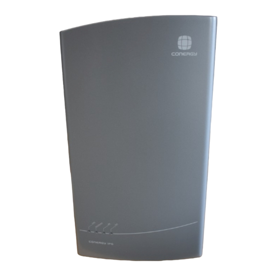
- Page 30 5 T r a n s p o r t a n d in s t a lla t io n External dimensions The external dimensions of the string inverter are: W x H x D 377 x 620 x 226 mm 377 mm 620 mm 226 mm...
-
Page 31: Wall Mounting
5 T r a n s p o r t a n d in s t a lla t io n 5.3.2 Wall mounting Conergy IPG string inverter series inverters are intended to be wall mounted. In order to facilitate installation they are supplied with a wall bracket, a drilling template and a basic installation equipment pack with wall plugs and screws. - Page 32 5 T r a n s p o r t a n d in s t a lla t io n 3. Fit the string inverter in place on the wall bracket. Fig. 5-4: Fitting the string inverter 4. Screw the bottom of the string inverter firmly in place. The bottom fixings of the string inverter are both to fix the device in place and also to ensure that it cannot accidentally be pushed off the wall bracket.
- Page 33 5 T r a n s p o r t a n d in s t a lla t io n In st ru c t io n m an u al C o n e r g y IP G s t r in g in v e r t e r s e r ie s...
-
Page 34: Basic Safety Instructions
6 In s t a lla t io n a n d c o m m is s io n in g In s t a lla t io n a n d c o m m is s io n in g Basic safety instructions Before starting any work on electrical installations please observe the following safety rules:... -
Page 35: Preparation For Installation
As a single-phase inverter, the string inverter only supplies power via phase L1. If you operate several inverters of the Conergy IPG string inverter series in parallel, the feed phase of the string inverter must be equally distributed over phases L1, L2 and L3 of the grid. -
Page 36: Connections
A 120 Ω terminator must be installed at the end of a CAN connection. (3) AC Out Grid connection (4) CTRL Connection for Conergy IPG easyconnect or external 230 V power supply for the Conergy IPG string vision inverter series inverter display. (5) DC– Solar system connections (6) DC+ Solar system connections All connections are provided with sealing plugs on delivery. -
Page 37: Connecting The Mains Cable
4 mm For devices with AC output of up to 4.6 kW a single string inverter of the Conergy IPG series is used. For the operation of systems with higher outputs, several string inverters are used. These are to be connected so that they are distributed over several phases. - Page 38 6 In s t a lla t io n a n d c o m m is s io n in g Fig. 6-2: Combination of several string inverters Inverter 3-phase energy meter of the utility Public power grid C o n e r g y IP G s t r in g in v e r t e r s e r ie s In st ru c tio n m an u al...
- Page 39 6 In s t a lla t io n a n d c o m m is s io n in g Connecting the mains cable 1. Remove the sheathing from the cable to a length of 35 mm. 2. Strip the cable for a length of 9 mm with a wire stripper. 3.
- Page 40 6 In s t a lla t io n a n d c o m m is s io n in g 5. Tighten the screws on the end piece (3) Fig. 6-5: Tightening the screws on end piece 6. Connect the end piece (3) to the connector cap (2) . Fig.
-
Page 41: Connecting The Solar System
6 In s t a lla t io n a n d c o m m is s io n in g 8. Connect the mains plug (1) into the socket (2) of the Conergy IPG series string inverter. Fig. 6-7: Connecting the mains plug to the socket A clicking sound confirms that the components are correctly connected. - Page 42 6 In s t a lla t io n a n d c o m m is s io n in g DANGER! Risk of electric shock! | Disconnect all cables and the plug-and-socket connection from the power supply. Tinned cable If copper strands are oxidised, the permitted limit values of the crimp connection contact resistance may be exceeded.
- Page 43 6 In s t a lla t io n a n d c o m m is s io n in g (1) Stripped wire (4) Connector plug (2) Cap of the connector plug or (5) Connector socket socket (3) Contact socket 4.
- Page 44 6 In s t a lla t io n a n d c o m m is s io n in g 8. Guide the wire through the connector cap and place the connector socket or connector plug onto the wire. Fig.
-
Page 45: Connecting The Conergy Sunreader
Fig. 6-12: Connecting the solar system Junction box If you have chosen to combine the Conergy IPG series inverter with the Conergy IPG easyconnect generator junction box, you will save valuable installation time. The solar system is connected to the Conergy IPG easyconnect and from there to the inverter. -
Page 46: Connecting The 230- V Power Supply
You must install a 120 Ω terminator at the end of a CAN connection (see chapter 6.10, page 46). If you do not use a Conergy SunReader, leave the sealing plugs in place on the connector. Connecting the 230- V power supply... -
Page 47: Connecting Further String Inverters
SunReader monitoring system, connect the Conergy IPG series string inverters to one another with a CAN cable. Connect the first inverter to the Conergy SunReader ( CAN In ) (see Fig. 6-1, page 35, pos. (1) ). Fit a terminator to the last inverter (see chapter 6.10, page 46). -
Page 48: Commissioning
If the solar irradiation is not sufficient to supply sufficient voltage for the power feed to the grid, the Conergy IPG series string inverter automatically reduces its output. If there is a fault during commissioning, you will find further information in chapter 7, page 49. - Page 49 6 In s t a lla t io n a n d c o m m is s io n in g LED indicators during commissioning Ready Solar Grid Fault M eaning system After switching on, approx. 10 seconds may elapse before the LED indicators are illuminated.
-
Page 50: Tr O U B Le S H O O T In G
It switches off. Overheating The Conergy IPG string inverter series inverter is designed to operate at an ambient temperature of up to 60°C. If this temperature is exceeded, the inverter interrupts the power feed to the grid and switches off. -
Page 51: Led Indicator Fault Messages
7 T r o u b le s h o o t in g Conergy Service Please contact Conergy Service in the event of faults. To enable Conergy Service to respond quickly and accurately, please provide the following information: | Invoice number (delivery note if applicable) - Page 52 The inverter notes that it is a critical fault and remains switched off permanently. Please contact Conergy Service. LED is illuminated LED is flashing (LED lights up regularly) LED is flashing...
-
Page 53: Fault Warnings On The Display
Fault warnings on the display If you have chosen a Conergy IPG string vision inverter series inverter, your inverter will have a high-resolution display. The inverter differentiates between faults and diagnostic information. Diagnostic information relates to temporary faults. - Page 54 Conergy Service. C o n e r g y IP G s t r in g in v e r t e r s e r ie s In st ru c tio n m an u al...
- Page 55 7 T r o u b le s h o o t in g In st ru c t io n m an u al C o n e r g y IP G s t r in g in v e r t e r s e r ie s...
-
Page 56: R E M O V A L
8 R e m o v a l R e m o v a l If you discover a fault to a string inverter of the Conergy IPG Series, please contact Conergy Service. If they tell you that Conergy will replace the unit, please remove it. First, switch off the public power supply and the solar system. - Page 57 8 R e m o v a l 3. Release the mains connector cable by inserting a screwdriver into the connector socket. Fig. 8-1: Releasing the mains cable 4. Turn the screwdriver slightly. 5. Pull the connector from the socket. 6.
-
Page 58: P P E N D Ix
9 A p p e n d ix A p p e n d ix Specifications Conergy IPG Conergy IPG 4000 and IPG 5000 and IPG 4000 vision 5000 vision Solar system Nominal solar system power 4,000 W 5,000 W Max. - Page 59 | Sinusoidal current form as AC and DC surge volt- age protection (Class D) Please check that the Conergy IPG Series string inverter complies with the requirements of your utility. Requirements may vary between utilities, e.g. voltage limit values may vary.
-
Page 60: Index
Installation 30 Block diagram 15 Junction box 4, 40, 45 Conergy IPG easyconnect 4, 40, 45 Conergy IPG sizer 4, 14 Conergy IPG string vision inverter 19, 52 LED 47, 50 Conergy Service 50 Lightning 14 Crimping 36 Maximum Power Point 17... - Page 61 9 . A p p e n d ix Removal 55 Specifications 59 Standards 6 Surge protection 17 System planning program 4 Wall mounting 30 Weight 26 In st ru c tio n m an u al C o n e r g y IP G s t r in g in v e r t e r s e r ie s...
- Page 62 Subject to technical modifications without notice. 2006 © Conergy AG...
Need help?
Do you have a question about the IPG Series and is the answer not in the manual?
Questions and answers