Table of Contents
Advertisement
Advertisement
Table of Contents

Related Manuals for Lab-Line 3608

Summary of Contents for Lab-Line 3608
- Page 1 4/02 OPERATION MANUAL MANUAL 056-602-00 REV. F LAB-LINE VACUUM OVENS MODEL NO. 3608 3608MP 3608-1CE 3608-5 3608-6CE 3618 3618-1CE 3618-5 3618-6CE 1999 North 15th Ave. , Melrose Park, IL 60160-1491 USA PHONE: (563) 556-2241 or (800) 522-5463; FAX: (563) 589-0516...
-
Page 2: Section Title
TABLE OF CONTENTS SECTION TITLE... - Page 3 Introduction Description Specifications Installation Features Operation Maintenance Troubleshooting Service Guides Replacement Parts Warranty SECTION 1 INTRODUCTION THANK YOU...
- Page 4 (319) 556-2241 or (800) 522-5463 ALL RIGHT RESERVED The information contained in this manual is the exclusive property of Lab-Line Instruments, Inc., and has been pro- vided solely to enable the users of the equipment described herein to operate and maintain such equipment. Any other use of this information, or the reproduction or transmission of all or any portion of this manual without prior written consent of the manufacturer is expressly prohibited.
-
Page 5: Specifications
WITH THE SURFACE OF THE CENTER SHELF WHEN TAKING A READING. MODEL DESIGNATIONS AND THEIR FEATURES: 3608, 3608-1CE, 3618 and 3618-1CE: Models with dial thermometer. 3608-5, 3608-6CE, 3618-5 and 3618-6CE: Models with LED temperature display. 3608MP: Model with microprocessor temperature controller. SECTION 3... -
Page 6: Shipping Carton
LED Display; range from 0ºC to 300ºC in 1ºC increments CHAMBER DIMENSIONS: 3608, 3608MP, 3608-1CE, 3608-5, 3608-6CE: 10"W x 12"D x 10"H (25 x 30 x 25 cm) 3618, 3618-1CE, 3618-5, 3618-6CE: 14"W x 20"D x 14"H (36 x 51 x 36 cm) -
Page 7: Hose Connections
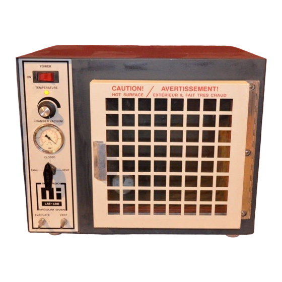
240V unit, attach proper power plug to match the power outlet. INSTALLATION: (Con’t) THERMOMETER: For models using the dial thermometer—3608, 3608-1CE, 3618 and 3618-1CE—place the thermometer so that the sensing element is in direct contact with the top shelf. The dial should be easily visible through the glass door. - Page 8 SECTION 5 FEATURES CONTROL PANEL: POWER TEMPERATURE CHAMBER VACUUM CLOSED...
- Page 9 #920-283-00 (BIMETALLIC THERMOSTAT), #560-223-00 (KNOB) ; #360-235-00 (LAMP LENS)* VACUUM GAUGE: Displays chamber level to 30-inches of mercury. #660-103-00 (3608,-1, 3618, -1) * VACUUM/VENT VALVE: 3-way valve draws, holds or releases a vacuum. #950-125-00* HOSE CONNECTORS: Marked "EVACUATE" and "VENT" for ¼" flexible tubing to connect to a gas source or vacuum pump.
- Page 10 #920-283-00 (BIMETALLIC THERMOSTAT), #560-223-00 (KNOB) ; #360-235-00 (LAMP LENS)* VACUUM GAUGE: Displays chamber level to 30-inches of mercury. #660-097-00 (3608-5,-6) OR $660-097-00 (3618-5, -6)* VACUUM/VENT VALVE: 3-way valve draws, holds or releases a vacuum. #950-125-00* HOSE CONNECTORS: Marked "EVACUATE" and "VENT" for ¼" flexible tubing to connect to a gas source or vacuum pump.
-
Page 11: Operation
EVACUATE VENT MODEL WITH MICROPROCESSOR CONTROLLER: POWER SWITCH: Power is on to the unit when this switch lamp is lit. (To reset the circuit breaker, press this switch to off, then on.) #440-359-00 (120V), #440-292-00 (240V)* TEMPERATURE CONTROLLER: PID based microprocessor controller maintains chamber temperature. -
Page 12: Loading The Oven
PRESSURE. WHEN THE VACUUM GAUGE READS ZERO, SHUT THE GAS OFF. The oven does not require very much gas to fill the chamber: 3608, 3608MP, 3608-1, 3608-5, 3608-6: Interior volume is 0.75 cubic feet 3618, 3618-1, 3618-5, 3618-6: Interior volume is 2.30 cubic feet... -
Page 13: Unloading The Oven
UNLOADING THE OVEN: When the bake is completed and the vacuum has been released or replaced as described above and on the previous page, push the power switch to OFF. Open the oven door and remove the dial thermometer. Take the contents from the chamber and re-insert the thermometer with the sensing element in direct contact with the center shelf. -
Page 14: Auto Tuning Procedure
3. SET POINT ADJUSTMENTS: The temperature controller normally displays the chamber temperature. To view or change the temperature set point proceed as follows: PRESS CONTROLLER View set point Decrease set point Increase set point Press and hold the star key and use either the up or down arrow key to adjust the set point to the desired temperature. -
Page 15: Temperature Calibration
After one minute has elapsed, the controller display will begin to alternate between showing the chamber temperature, tunE and At.SP. Allow the program to run until the display again shows only the chamber temperature. OPERATION: (Con’t) TEMPERATURE CONTROLLER: (Con’t) TEMPERATURE CALIBRATION: Place a calibrated thermometer near the approximate geometric center of the chamber in a position that would allow it to be read through the glass door. -
Page 16: Maintenance
SECTION 7 MAINTENANCE BE ADVISED: NOTE: MAKE NO ATTEMPT TO SERVICE OR REPAIR A LAB-LINE PRODUCT UNDER WARRANTY BEFORE CONSULTING YOUR LAB-LINE DEALER. AFTER THE WARRANTY PERIOD, SUCH CONSULTATION IS STILL ADVISED, ESPECIALLY WHEN THE REPAIR MAY BE TECHNICALLY SOPHISTICATED OR DIFFICULT. - Page 17 CARE AND CLEANING OF STAINLESS STEEL: CAUTION: DISCONNECT UNIT FROM POWER SOURCE PRIOR TO CLEANING. WE RECOMMEND ALL SERVICE BE PERFORMED BY QUALIFIED SERVICE PERSONNEL. WARNING: ELECTROLYSIS CAN DAMAGE STAINLESS STEEL. THIS OCCURS WHEN AN OBJECT IS ALLOWED TO REST DIRECTLY ON THE SURFACE OF STAINLESS STEEL, TRAPPING MOISTURE THAT BECOMES OXYGEN-STARVED, BUT IS SURROUNDED BY WATER-CONTAINING OXYGEN.
-
Page 18: Special Considerations
MAINTENANCE: (Con’t) THE ALLOY CALLED STAINLESS: Stainless steel is an alloy of steel with chromium and nickel which increase the metal’s resistance to rust and corrosion. Yet, if not properly cared for, stainless steel can rust and corrode. Exposure to air provides the passivation, or oxide layer coating, for clean stainless by producing a thin, durable chromium-oxide film that forms rapidly on the alloy surface to give stainless its characteristic “stainless”... -
Page 19: Cleaning Methods
MAINTENANCE: (Con’t) BE ADVISED: NEVER USE THE FOLLOWING ON STAINLESS STEEL: Aqua regia Ferric chloride Iodine Sodium acid Sodium azide Chemical spills, especially those agents listed here, should be removed as soon as possible and the stainless steel surface cleaned with mild soapy water followed by a clean water rinse. - Page 20 • Alcohol BE ADVISED: THIS INFORMATION IS INTENDED AS GUIDELINES ONLY AND LAB-LINE INSTRUMENTS, INC. MAKES NO CLAIM AS TO THE SUITABILITY TO ANY PARTICULAR SITUATION. CONSULT YOUR STAFF CHEMIST TO DETERMINE WHAT WOULD BE BEST FOR YOUR STAINLESS STEEL PRODUCT AND LABORATORY.
-
Page 21: Troubleshooting
SECTION 8 TROUBLESHOOTING There are few oven parts that will require repair. In case of a malfunction, the control thermostat, limit thermostat, heater status lamp, heaters, power switch, vacuum/vent valve and vacuum gauge are fairly easy to replace. Use this troubleshooting guide to find a possible source of any problem, then test and/or make replacement as described. - Page 22 TROUBLESHOOTING: (Con’t) SYMPTOM POSSIBLE CAUSES OF PROBLEM Heater status lamp is Replace the heater status lamp. out when cold oven is heating up: The thermostat is set Move thermometer in contact with shelf. at maximum and thermometer does Check both thermostats—replace if bad. not register or only registers partial Make ohmmeter check of heater resistance and replace...
- Page 23 CAUTION: PUSH THE POWER SWITCH OFF AND UNPLUG THE OVEN BEFORE ATTEMPTING ANY SERVICE OR REPAIRS ON THE UNIT. CONTROL PANEL REMOVAL & INSTALLATION: • Tilt the oven back to remove screws under the control panel. Carefully pull the bottom forward until the top is free. Pull it 3-inches (at most) from the oven to reach behind and remove internal copper tubing from the vacuum gauge.
- Page 24 • Remove the status lamp lead at the thermostat and cut the other lead close to the heater status lamp. • Pry the retaining clip from the old lamp and pull it from the control panel. Push the new lamp in place and install the same retaining clip on it. Attach the new lamp leads to the thermostat and to the cut wire, referring to the wiring schematic.
- Page 25 • Remove the control panel valve knob by loosening the hex setcrew. Then unscrew the valve retaining nut on front of the panel and take the old valve from the back of the panel. • Install the new valve in the panel and tighten the retaining nut. Replace the valve knob and tighten the setscrew.
-
Page 26: Back Panel Components
HEATER REPLACEMENT: Disconnect power and remove the back panel (edge screws) and insulation from the back and sides. Note that oven Models 3608 and 3608-1 have 2 heaters, one located on each side of the chamber; Models 3618 and 3618-1 have 4 heaters, 2 located on each side. - Page 27 • Replace the oven housing and control panel and repack side as well as back insulation, and replace the back panel. DOOR AND GASKET REPAIRS: DOOR GASKET REPLACEMENT: After pulling the old gasket from its groove, remove all dirt and foreign matter from the groove and from the mating surface on the oven.
-
Page 28: Replacement Parts
485-360-15 Wiring Schematic: 229-150-00 NEED A PART? CALL THE LAB-LINE PARTS HOTLINE. CALL: (319) 556-2241 or (800) 522-5463; FAX: (319) 589-0516. LAB-LINE RESERVES THE RIGHT TO CHANGE SPECIFICATIONS WITHOUT PRIOR NOTICE. AS ILLUSTRATED AS ILLUSTRATED AS ILLUSTRATED AS ILLUSTRATED AS ILLUSTRATED... -
Page 29: Warranty
Lab-Line’s warranty provided hereunder shall be null and void and without further force or effect if there is any (i) repair made to the product by a party other than Lab-Line or its duly authorized service representative, (ii) misuse (including use inconsistent with... - Page 30 Page 2 of 2 12 MONTH PARTS WARRANTY: • All Environmental Chambers • Low Temperature B. O. D. Incubators • Animal Study Chamber • Controlled Environment Centers • Biological Work Station • Refrigerators, Freezers • Chromatography Refrigerators (5 year parts warranty on compressor only) •...
- Page 31 FIRST IN INSTRUMENTS SERVICING SCIENCE, INDUSTRY, RESEARCH AND EDUCATION SINCE 1908.
-
Page 33: Accessory Checklist
The following loose parts and accessories are packed with this unit. Before discarding any packing materials, please be sure that nothing has been overlooked. MODEL NO: 3608, 3608MP, 3608-1CE, 3608-5, 3608-6CE, 3618, 3618-1CE, 3618-5, 3618-6CE CHECKED BY: __________ DATE __________...
Need help?
Do you have a question about the 3608 and is the answer not in the manual?
Questions and answers