
Subscribe to Our Youtube Channel
Related Manuals for Metronic FP4

Summary of Contents for Metronic FP4
- Page 1 FP4, FP4W Flow totalizer with data recording OPERATING MANUAL Version: 190226EN This operating manual is also available on the CD-ROM.
- Page 2 FP4, FP4W Before installation, carefully read all the instructions, especially those concerned with Environment, Health and Safety (EHS). The device has been manufactured according to the requirements of relevant EU directives. These instructions must be stored in a safe place near the installation of the device at all times.
-
Page 3: Table Of Contents
3.3 Available options ....................11 3.4 Galvanic separation in the device ............... 11 MECHANICAL INSTALLATION ................12 4.1 Mechanical installation of the FP4 device ............12 4.2 Mechanical installation of the FP4W device ............13 ELECTRICAL INSTALLATION ................14 5.1 Configuration of jumpers inside the device ............15 5.1.1 Configuration of jumpers related to analogue inputs (IN1, IN2) .... - Page 4 FP4, FP4W 7.2 Change of the language ..................28 7.3 Recommended order for configuration of the device .......... 28 7.4 Reading and saving files using the USB port ............30 7.5 Factory settings ....................31 TECHNICAL SPECIFICATIONS................32 ENTITY LAUNCHING THE PRODUCT ON EUROPEAN UNION MARKET ..36 10 USER SCREENS ...
- Page 5 13.2 Print screen ......................56 13.3 Web server ......................56 13.4 Software for PC ....................59 13.4.1 FP4 Config ....................59 13.4.2 FP4-RP (FP4RPplus) ................... 59 14 FAILURE SYMBOLS ..................61 15 MODBUS RTU / MODBUS TCP TRANSMISSION PROTOCOL ....... 62 15.1 General information.....................
-
Page 6: Safety Information And Instructions
FP4, FP4W 1 SAFETY INFORMATION AND INSTRUCTIONS Safe operation of this product can only be guaranteed if it is properly installed, commissioned, used and maintained by qualified personnel in compliance with the operating instructions. General installation and safety instructions for pipeline and plant construction, as well as the proper use of tools and safety equipment must also be complied with. - Page 7 Check that the product is suitable for use with the application. Determine the correct installation and physical situation. Prior to installation of Metronic AKP products, take into account any environmental limitations of devices, specified in the manual.
- Page 8 They may cause discoloration or scratch the surfaces of device. Disposal The FP4/FP4W contains a battery. On disposal of the unit or component, appropriate precautions should be taken in accordance with Local/National regulations. Unless otherwise stated in the Installation and Maintenance Instructions, with the exception of the battery, this product is recyclable and no ecological hazard is anticipated with its disposal providing due care is taken.
-
Page 9: Delivery Content, Accessories And Storage
FP4, FP4W 2 DELIVERY CONTENT, ACCESSORIES AND STORAGE Prior to dispatch, each Metronic AKP device is inspected and calibrated to ensure proper and efficient operation. CAUTION Upon receipt, each package should be inspected for any potential damage. The content of the whole package should also be checked and the actual number of elements should be compared against the manufacturer's list of items presented in the consecutive subsection. -
Page 10: General Product Overview
RS-485 port (Modbus RTU protocol) and can work in distributed control systems. The FP4 device is supplied from 24 VDC source, while the FP4W device is supplied from 230 VAC source. Detailed information concerning the power supply is given in... -
Page 11: Available Options
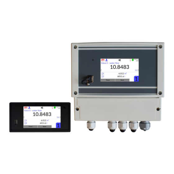
3.3 Available options Device is available in panel mount version (FP4) and in wall mount version (FP4W). Both device versions have the same features. The configuration of the settings described in the Operating Manual is the same for both versions of the device. -
Page 12: Mechanical Installation
SAFETY INFORMATION. 4.1 Mechanical installation of the FP4 device FP4 is a panel-mounted device. It can be mounted into panels at least 1 mm thick. (+1) (+0.7) Before installation, a 138 mm X 68 mm rectangular opening must be cut out in the panel . -
Page 13: Mechanical Installation Of The Fp4W Device
FP4, FP4W The device cannot be exposed to direct heat generated by other equipment. When assembled, the operating device cannot be affected by interference from other components (contacts, power relays, inverters). 4.2 Mechanical installation of the FP4W device FP4W is a wall-mounted device. Device dimensions without cable glands: 213 mm x 185 mm x 102 mm (width x height x depth). -
Page 14: Electrical Installation
INFORMATION. Power supply and all signal wires are connected to plug-in screw terminals, situated at the rear panel of the device (FP4) or spring terminals at the bottom of the device (FP4W). Maximum wires cross-section area is 1.5 mm . Both wire and cord cables can be used. -
Page 15: Configuration Of Jumpers Inside The Device
The rear panel of the FP4 device should not be draw out more than necessary to connect jumpers. In the upper part of the FP4 housing there is a label showing the correct way of configuration of the jumpers inside the device and electrical connections. In the lower right corner of the label there is a place in which current configuration of the device can be marked. -
Page 16: Configuration Of Jumpers Related To Analogue Inputs (In1, In2)
FP4, FP4W Fig. 5.4 Layout of jumpers inside the FP4W device. 5.1.1 Configuration of jumpers related to analogue inputs (IN1, IN2) INPUT 1 (IN1) INPUT 2 (IN2) Input type: J11 J12 J13 J14 J15 J16 J17 J21 J22 J23 J24 J25 J26 J27... -
Page 17: Wiring Transducers To Analogue Inputs
FP4, FP4W 5.2 Wiring transducers to analogue inputs The device has two analogue inputs, which can work in one of the selected modes: 0/4-20mA (active/passive transducers), R/RTD type input, U type input. It should be taken into account that the configuration of jumpers inside the device is necessary. Detailed... -
Page 18: Wiring Transducers To Puls Type Inputs
FP4, FP4W R/RTD input (2-wire connection) Fig.5.7 Wiring diagram for R/RTD input type (2-w.). Terminal No. Description Terminal No. (FP4) (FP4W) Not used U+ / I+ Sens input for 2-wire connection U- / I- Sens input for 2-wire connection U-type input (transducers with voltage output) Fig. - Page 19 FP4, FP4W OC/contact input type (OC type transmitter or passive contact) Fig. 5.9 Wiring of OC transmitters to PULS type inputs. Terminal No. Description Terminal No. (FP4) (FP4W) Not used (F+) (F+) Input (+) (F+) (F+) (F-) (F-) Input (-)
- Page 20 FP4, FP4W NAMUR input type Fig. 5.11 Wiring of NAMUR transmitters to PULS type inputs. Terminal No. Description Terminal No. (FP4) (FP4W) +12V OUT (22 mA max) /I+ Transducer power supply. Each output is protected by resetable polymer 50 mA fuse.
-
Page 21: Wiring Diagram For The Analogue Output
FP4, FP4W 5.4 Wiring diagram for the analogue output Fig. 5.13 Wiring diagram for the analogue output. Notes: Current source passive – requires external voltage source. 5.5 Wiring diagram for the relay outputs Fig. 5.14 Wiring diagram for the relay outputs. -
Page 22: Ethernet Port
The ‘common’ wire should be used for all RS-485 ports. For FP4 device as a common signal the power supply ‘-’ (terminal no. 26) or functional ground (terminal no. 27) have to be used. - Page 23 FP4, FP4W To supply the device from 24 VDC source, change the configuration of the jumpers inside the device (the 24IN jumpers configuration). In this configuration, additional devices cannot be supplied via terminals 1-4 (max. 100 mA). Fig. 5.17 Jumpers inside the FP4W device for changing the supply voltage.
- Page 24 FP4, FP4W Device supplied with 24 VDC source Fig. 5.21 Configuration of jumpers in the FP4W device (device supplied with 24 VDC source). Fig. 5.22 Power wiring diagram (device supplied with 24 VDC source). Fig. 5.23 Diagram of wiring the power supply and I/O signals to the FP4W device (device supplied with 24 VDC source).
-
Page 25: Front Panel And Main Function Buttons
6.1 Front panel A 4" LCD touch screen is built into the front panel of the device which is the basic tool of communication with the user. Fig. 6.1 Front panel of FP4 device. The display is consists of: Title bar with functional icons, having an information function. -
Page 26: Title Bar
FP4, FP4W 6.1.1 Title bar Fig. 6.2 Title bar. The title bar is located in the top part of the screen and has mainly the informative function, but there are also function icons. Manufacturer logo: function icon, tap to make screenshot to internal memory of ). -
Page 27: First Start Up And Key Activities
7.1 Access control, login and change of user password 7.1.1 Access control In the FP4 device, access control module was applied aimed at limiting the possibility of changing the parameters of work of the device and copying the data from the device by unauthorized users or operators. -
Page 28: Changing The Password
In addition to the change of the password, the Administrator can also change the User password without the need to know the previous password. If the Administrator's password is forgotten, contact the Metronic AKP Service. 7.2 Change of the language To change the language, in the first step user should login as the Administrator (information in section Login). - Page 29 Due to the use of the same interface, device configuration using the computer software FP4 Config.exe takes place in the same way as configuration from the device level. After completing the configuration using the computer, record the setting file *.par using a USB...
-
Page 30: Reading And Saving Files Using The Usb Port
FP4, FP4W 7.4 Reading and saving files using the USB port To read or write files using the USB flash memory select the button from the title bar and then the icon. On the left side of the screen, there is a window with a list of archive files and screenshots. -
Page 31: Factory Settings
FP4, FP4W 7.5 Factory settings To restore the device to the factory settings, first login as the Administrator. Before selecting the factory settings option, it is recommended to save the previous settings on the USB flash memory. Otherwise, the settings will be lost. -
Page 32: Technical Specifications
Display size 86.4 mm X 52.5 mm Keyboard resistive touch panel Additional indication LED RGB USB Port - front panel (FP4, FP4W) USB 2.0 (with limited functionality, for connection Version of FLASH storage) USB standard ‘A’ type socket Connector type... - Page 33 213 mm x 215 mm x 102 mm Weight c.a. 0.8 kg Protection class IP54 Environmental conditions (FP4, FP4W) FP4: 0 .. +50 °C Ambient temperature FP4W: -20 .. +50 °C Relative humidity 5 .. 95% (without steam condensation) Maximum altitude <2000 m above sea level...
- Page 34 Conversion characteristic (for U) Linear or User =+25 °C) ±0.5% of range Initial accuracy (T PULS TYPE INPUTS (FP4, FP4W) Number of inputs 0.01 Hz .. 10 kHz, additional filter disabled Measurement range 0.01 Hz .. 1 kHz, additional filter enabled ...
- Page 35 Outputs type Solid state relays Maximum voltage 60 V AC/DC Maximum load current 0.1 A ANALOGUE OUTPUT 4-20mA (FP4, FP4W) Output signal 4-20 mA (3.6 .. 22 mA) Current loop supply no (external supply required) Maximum voltage between I+ and I- 28 VDC =0 Ω)
-
Page 36: Entity Launching The Product On European Union Market
FP4, FP4W 9 ENTITY LAUNCHING THE PRODUCT ON EUROPEAN UNION MARKET Manufacturer: METRONIC AKP s.c. st. Żmujdzka 3 PL 31- 426 Kraków, Poland Tel.: (+48) 12 312 16 80 www.metronic.pl Vendor:... -
Page 37: User Screens
FP4, FP4W 10 USER SCREENS Switching between windows is possible with using: arrows , (displayed on the sides of the screen) and the main menu icon (displayed on the title bar). Arrows and the main menu icon shows up after touching the screen. -
Page 38: Archive
FP4, FP4W Fig. 10.2 An example view of the ‘Single result’ window. Using the arrows (appearing on the sides of the screen), a change of the displayed channels is possible. Keeping the arrows down for a few seconds enables sequentially displaying other channels. -
Page 39: Alarms
FP4, FP4W 10.4 Alarms The Alarms window contains alarm statuses for all channels. This window is displayed only when at least one alarm is enabled. For each of the channels is assigned a single rectangle divided into two parts corresponding to the first and second alarm respectively. -
Page 40: Main Menu
FP4, FP4W Information about the settings of the relay outputs and the analogue output can be verified in the I/O settings window. Fig. 10.5 An example view of the ‘Output’ window. 10.6 Main Menu To display Main Menu window, select the... -
Page 41: Programming Settings
FP4, FP4W 11 PROGRAMMING SETTINGS To accept any changes to the device setting, first confirm them using button in the right bottom part of the screen, and then click on the Exit icon. It will be displayed a message requesting user to confirm the changes. -
Page 42: Display
FP4, FP4W Sound for buttons: Disabled (Disabled, Enabled) Sound for new alarms: Disabled (Disabled, Enabled) Changing DST: Disabled (Disabled, Enabled) [1]: Selection from the drop down list. [2]: Enables to insert any description (name) of the device. [3]: Device ID enables to assign an individual ID number. The ID is also included in archive files names. -
Page 43: Service
FP4, FP4W 11.1.4 Service The ‘Service’ tab is only available to the Administrator and enables execute following tasks: Restart – results in restart of the device. Restore Factory Settings – using the function will result in deleting all of the earlier... -
Page 44: Outputs
FP4, FP4W 11.2.1 Outputs Relay outputs (RL1 .. RL4) Mode: Disabled (Disabled, Normally open, Normally closed, Pulsation) [1]: In the Normally open mode the relay circuit is closed when an event is reported (e.g. exceeded alarm-control threshold). In the Normally closed mode, the relay circuit is normally closed when idle, and is opened when an event is reported. -
Page 45: Rs-485 Port
FP4, FP4W IP address: [value] ModbusTCP port: [value] Mask: [value] Gate: [value] [1]: These parameters should correspond to the network where the device is intended to operate. [2]: It is recommended to use the 502 port dedicated to Modbus TCP, port 80 is not allowed (reserved for the device’s web server). -
Page 46: Inputs
FP4, FP4W Fig. 11.4 An example view of the ‘Channel’ settings window (Measurement channel type, input IN1). 11.4.1 Inputs Channels 1 and 2 (Analogue inputs IN1 and IN2) Channel Type: Measurement Input Number: [number (mode)] Characteristic: Linear (Linear, User, 1:1 (TEST), sensor) [1]: Information about the channel type - Measurement. -
Page 47: General
FP4, FP4W Fig. 11.5 Entering the formula in the Math Channel. The Operation field enables the selection of one of the four available formulas using the drop-down list and symbols: +, -, ˣ, . Symbol Formula [(AˣKx) + (BˣKy)] + C [(AˣKx) - (BˣKy)] + C... -
Page 48: Totalizers
FP4, FP4W fluctuations can be falsified by "smoothing out" the ascending and descending slopes, or by eliminating short pulses. The filter time constant should be customized to the maximum speed of changes in the measured process. [5]: It enables on/off the archiving of the results to a file in internal archive memory. -
Page 49: Alarm
FP4, FP4W 11.4.1 Alarm Fig. 11.7 An example view of the 'Channel’ setting window – Alarm 1. Mode: Disabled (Disabled, Low, High) Type: Alarm (Alarm, Control) Level: [None] (value) Hysteresis: [None] (value) Colour: Disabled (Disabled, Green, Yellow, Red) Output: -- (--, RL1, .., RL4) -
Page 50: Archive Settings
FP4, FP4W MAIN ARCHIVE interval I to MAIN ARCHIVE interval II – more information about archive interval in section Archive settings. 11.5 Archive settings Selection of archive work settings is possible using drop-down lists. Fig. 11.8 An example view of the 'Archive’ setting window. -
Page 51: Archive
FP4, FP4W 12 ARCHIVE 12.1 Start, resume and stop archiving To display Archive window, use arrows: and . To display arrows, touch the screen. Using the function buttons, it is possible to start, resume or stop the archiving process. -
Page 52: Archive Files Organization
Each archive file contains a header, with the following information: DEVICE MODEL, FW VERSION, SERIAL NUMBER, ID, NUMBER OF ROW, ARCHIVE TYPE, CRC1 – device model, for FP4/FP4W it is FP4 DEVICE MODEL – the firmware version in which the archive was created, updating... -
Page 53: Totalizer Archive
FP4, FP4W 12.6.2 Totalizer archive Organization of additional header in the totalizers archive file: CHANNEL, DESCRIPTION, TOTALIZER 1 TYPE, TOTALIZER 1 UNIT, TOTALIZER 2 TYPE, TOTALIZER 2 UNIT – the channel number CHANNEL – channel description, depending on the settings in the device DESCRIPTION –... -
Page 54: Copying Archive Files From The Device
FP4, FP4W – Changed date SYS:DATE CHANGED – Reset auxiliary values for "x" channel SYS:CHx: AUX VALUES RESET (totalizers, timers) SYS: ALL CHANNELS: AUX VALUES RESET – Reset auxiliary values on all channels (totalizers, timers) – Acknowledged alarms AL:ACK – Activated the "y" alarm on the "x" channel AL:CHx ALy ON –... -
Page 55: Additional Functions
To cancel implemented changes, press the button. In the FP4 Config program it is possible to add a characteristic from the computer level. The file with characteristics points must be in *.csv format. The columns in the file must be signed as ‘x’ (previous column) and ‘y’ (next column). Use a decimal point. -
Page 56: Print Screen
FP4, FP4W To copy the settings, from the list in the top part of the Channels setting window select the channel which is to be copied and then select the button. Then, choose the channel to which the settings are to be copied and click the button. - Page 57 FP4, FP4W Choose language by clicking on the appropriate flag icon. Then, log in with the User’s password. In case that this password is disabled, press the Login button without entering any characters. Fig. 13.3 Login to the web server.
- Page 58 FP4, FP4W and the state of output relays marked as RL1-RL4 (the icon indicates that the output is closed, the icon indicates that the output is opened). It should be taken into account, that the page is not refreshed automatically. To refresh data, press the Refresh button at the bottom of the screen.
-
Page 59: Software For Pc
In extended version FP4-RPplus.exe there is possibility to download archive files from the device via Ethernet connection. Detailed information is in instruction manual for the FP4-RP program. Fig. 13.8 An example window view in the FP4-RPplus program, downloading archive files from the device via Ethernet connection. - Page 60 FP4, FP4W Fig. 13.9 An example window view in the FP4-RP program, data presented in a graph (data archive). Fig. 13.10 An example window view in the FP4-RPplus program, data presented in a table (totalizer archive).
-
Page 61: Failure Symbols
FP4, FP4W 14 FAILURE SYMBOLS Fault situation related to a particular channel are marked with a relevant symbol on the display: -------- Channel switched off (analogue output switched off), for the switched off channels the single result window is not displayed. -
Page 62: Modbus Rtu / Modbus Tcp Transmission Protocol
FP4, FP4W 15 MODBUS RTU / MODBUS TCP TRANSMISSION PROTOCOL 15.1 General information Process values and totalizers are available as holding registers and input registers. It is only possible to read the data. 15.1.1 Data types Reg (Bit 15…0) - Page 63 FP4, FP4W Addresses table of Totalizer 1 (64bit double) No. measuring Size Register number Modbus address channel (in registers) 300012 / 400012 4 (64bit double) 300016 / 400016 4 (64bit double) 300020 / 400020 4 (64bit double) 300024 / 400024...
- Page 64 FP4, FP4W Addresses table of Totalizer 1 (int 64bit) No. measuring Size Register number Modbus address channel (in registers) 300084 / 400084 4 (int 64bit) 300088 / 400088 4 (int 64bit) 300092 / 400092 4 (int 64bit) 300096 / 400096...
Need help?
Do you have a question about the FP4 and is the answer not in the manual?
Questions and answers