Table of Contents

Summary of Contents for Masibus MC-1-DE
- Page 1 OPERATOR’S MANUAL GPS Time Sync Unit Masibus Automation And Instrumentation Pvt. Ltd. B/30, GIDC Electronics Estate, Sector-25, Gandhinagar-382044, Gujarat, India +91 79 23287275-79 +91 79 23287281-82 Email: support@masibus.com Web: www.masibus.com...
-
Page 2: Table Of Contents
3. GPS Fundamentals ..........................9 4. MC-1-DE Specification ........................11 5. Unit Front Panel Description ...................... 15 5.1 GPS TIME SYNC UNIT MC-1-DE Front Panel ............15 6. GPS TIME SYNC UNIT MC-1-DE Installation ................19 6.1 GPS Antenna and Cable Information ..............20 6.2 Unit Installation .................... - Page 3 Model: MC-1-DE Doc Ref. No:-m05dom102 Issue No:-00 9.6 NTP Hierarchical Time Distribution: ..............56 10. Relay and Pulse Outputs ......................59 10.1 Relay Contact Outputs..................59 10.2 Pulse Outputs ....................59 11. Ethernet Communications: Telnet, SNMP................61 11.1 Telnet ......................61 11.2 SNMP ......................
- Page 4 IST OF IGURES Figure 1 Basics of GPS ........................9 Figure 2 GPS Time Sync Unit Model MC-1-DE Front Panel ............15 Figure 3 Power Supply terminals ....................15 Figure 4 Fuse..........................16 Figure 5 Alarm Relay Terminals ....................16 Figure 6 Additional event Terminals ....................
-
Page 5: Introduction
Issue No:-00 1. INTRODUCTION Foreword Thank you for purchasing GPS Time Sync Unit MC-1-DE .GPS Time Sync Unit is available in Din Rail Mount/Wall Mount/Panel Mount This manual describes the basic functions and operation methods. Please read through this user’s manual carefully before using the product. -
Page 6: Notice
Doc Ref. No:-m05dom102 Issue No:-00 The GPS TIME SYNC UNIT MC-1-DE unit occupies the size 72mm(H) X 143mm(L) X 140mm(D) (IP 20 Enclosure).It is supplied complete with all hardware and software required for the installation, in- cluding the Antenna, Antenna mounting kit, 15 meters Antenna cable ,02 meter RS – 232 cable and 02 meters RG58 Co-axial cable. -
Page 7: Trademarks
Masibus product or software, whatsoever or howsoever caused. In no event shall Masibus be liable for any direct, indirect, special or consequential damages whether the claims are grounded in contract, tort (including negligence), or strict liability. -
Page 8: Unpacking The Mc-1-De
50 meter. All Packaging list depends upon commercial terms and condition also as per order. 2.1.2 Optional Items GPS TIME SYNC UNIT MC-1-DE model can also be shipped with below optional items only as per customer order. •... -
Page 9: Gps Fundamentals
Issue No:-00 3. GPS Fundamentals GPS Fundamentals GPS TIME SYNC UNIT MC-1-DE DE device is a GPS/GNSS based receiver Unit which provides acc which provides accu- rate time output with 1PPS signal. Satellite Navigation system is a system of satellites that provide rate time output with 1PPS signal. - Page 10 Model: MC-1-DE Doc Ref. No:-m05dom102 Issue No:-00 GLONASS based satellite navigation system is maintained by Russia, a fully functional navigation constellation in 1995. After the collapse of the Soviet Union, it fell into disrepair, leading to gaps in coverage and only partial availability. It was recovered and fully restored in 2011. It provides an alter- native to Global Positioning System (GPS) and is the second alternative navigational system in oper- ation with global coverage and of comparable precision.
-
Page 11: Mc-1-De Specification
Model: MC-1-DE Doc Ref. No:-m05dom102 Issue No:-00 4. MC-1-DE Specification Timing Accuracy < 15 ns with GPS Receiver (Receiver is locked on fixed position) Positioning Accuracy <10m SEP (with Selective Availability [SA] Disabled). Receiver Input 1575.42 MHz L1 C/A Code. - Page 12 Model: MC-1-DE Doc Ref. No:-m05dom102 Issue No:-00 Maximum Length: 100 meters (Up-to 400 meters using additional line am- plifier) Coverage: 360 Degree Ingress Protection: IP20 Pulse 1 PPS Accuracy: <150 ns Accuracy with GPS locked Output: TTL Output (Impedance 250 Ω) Pulse Width: 200 (200 mS High &...
- Page 13 Model: MC-1-DE Doc Ref. No:-m05dom102 Issue No:-00 Mode: Server Time format: UTC Network Interface: 10/100 Mbps Interface: RJ-45 Connector (Front Panel) Additional Event Outputs Two independent configurable Event outputs Configuration: Individual configurable time period and pulse ON time through Serial Terminal Time Period: 1 to 86400 seconds (24 Hr.) max...
- Page 14 Model: MC-1-DE Doc Ref. No:-m05dom102 Issue No:-00 Temperature Operating: 0° C to +55° C Storage: -20° C to +80° C ENVIRONMENT Humidity 20 - 90% (Non-condensing) RS232-to-RS485 Converter LINE AMPLIFIER, SURGE ARRESTOR EXTRA MODULES Time Distribution Rack (TDR-4) (OPTIONAL) Time Signal Repeater (TSR-4)
-
Page 15: Unit Front Panel Description
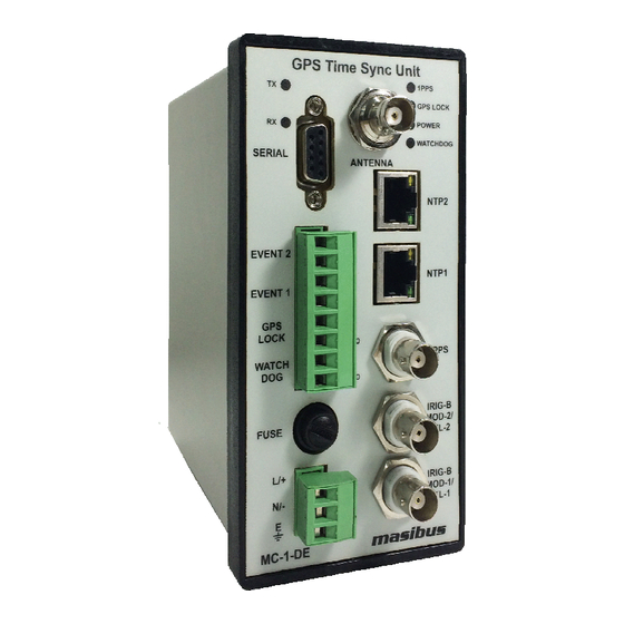
GPS TIME SYNC UNIT MC-1-DE Front Panel Below image shows GPS TIME SYNC UNIT GPS TIME SYNC UNIT MC-1-DE model front panel. The front panel is equipped model front panel. The front panel is equipped 6 LED status indicators and various outputs of... -
Page 16: Figure 4 Fuse
GPS TIME SYNC UNIT MC-1-DE provides serial time frame T-format / NGTS format / NGTS/ NMEA for- mat on its terminal and can also be used for inal and can also be used for GPS TIME SYNC UNIT MC-1-DE configuration. This configuration. This Page 16 of 76... -
Page 17: Figure 8 Irig B Output Terminal
Available only when serial output is available. Available only when serial output is available. 7. IRIG – B1 Output GPS TIME SYNC UNIT MC-1-DE DE provides IRIG-B TTL and IRIG-B AM output through BNC conne B AM output through BNC connec- tor on Front panel of unit as shown in panel of unit as shown in Figure 8. -
Page 18: Figure 11 Ntp1 Output Terminal
Issue No:-00 10. NTP1 GPS TIME SYNC UNIT MC MC-1-DE is equipped with 10/100 Mbps Ethernet output for NTP, SNMP is equipped with 10/100 Mbps Ethernet output for NTP, SNMP and Telnet communication as shown in and Telnet communication as shown in figure 11. -
Page 19: Gps Time Sync Unit Mc-1-De Installation
Model: MC-1-DE Doc Ref. No:-m05dom102 Issue No:-00 6. GPS TIME SYNC UNIT MC-1-DE Installation Before beginning with unit installation, please follow important safety statements for avoiding in- stallation practices causing malfunctioning of the device as mentioned below. It is recommended to get the installation of this product to be done... -
Page 20: Gps Antenna And Cable Information
This section should help you with installing the GPS antenna and antenna cable(s) and connecting them to the model GPS TIME SYNC UNIT MC-1-DE. It should also be a source of information if you should need to trouble shoot the antenna cable system. These Unit achieve their accuracy. By com- paring and adjusting the internal clock signal to the incoming GPS signal. -
Page 21: Figure 14 Antenna Mounting
Model: MC-1-DE Doc Ref. No:-m05dom102 Issue No:-00 and if the antenna is mounted in a less favorable location, it may work however GPS antenna signals and if the antenna is mounted in a less favorable location, it may work however GPS antenna signals and if the antenna is mounted in a less favorable location, it may work however GPS antenna signals reception capability may be somewhat limited/deteriorated during certain hours of the day. - Page 22 In-line amplifiers overcome signal attenuation in by amplifying the GPS signal. Use the in-line amplifi- er for cable runs of 100 to 200 meter. Please contact a masibus Sales Representative for information on how to extend the distance from the antenna to the receiver.
- Page 23 ESD. 6.1.3.1 Checking the Antenna Voltage GPS TIME SYNC UNIT MC-1-DE unit provides +5 Vdc to the GPS antenna though its Antenna con- nector on unit front panel, which is carried through the antenna cable. Nominal antenna current is 10 mA.
- Page 24 Model: MC-1-DE Doc Ref. No: Doc Ref. No:-m05dom102 Issue No:-00 6.1.5 Technical Details on GPS Antennas and Cables Technical Details on GPS Antennas and Cables Antenna Cable Length and Loss Considerations Length and Loss Considerations Standard Antenna Cable The standard antenna cable assembly included with...
-
Page 25: Unit Installation
The male Type BNC connector on the opposite end of the antenna cable connects to the female Type BNC connector on the front panel of the GPS Time Sync Unit. 6.2 Unit Installation After GPS Antenna installation is complete, GPS TIME SYNC UNIT MC-1-DE unit can be installed as per below procedures. •... -
Page 26: Mechanical Dimensions
Model: MC-1-DE Doc Ref. No: Doc Ref. No:-m05dom102 Issue No:-00 6.3 Mechanical Dimensions Dimensions Figure Figure 16 Wall Mount Mechanical Dimension Layout Figure Figure 17 Panel Mount Mechanical Dimension Layout Page 26 of 76 User’s Manual... -
Page 27: Wiring Diagram
Model: MC-1-DE Doc Ref. No:-m05dom102 Issue No:-00 Figure 18 18 Din Rail Mount Mechanical Dimension Layout 6.4 Wiring Diagram Figure Figure 19 Wiring Diagram of GPS Time Sync Unit Page 27 of 76 User’s Manual... -
Page 28: Gps Time Sync Unit Mc-1-De Power On
7.1 Receiver Boot-up mode When GPS TIME SYNC UNIT MC-1-DE unit is power up, the time of unit depends on the GPS re- ceiver RTC data. At every Power ON, unit is in UNLOCK mode initially. If GPS antenna is connected after Power ON or was already connected while powering up the unit, the time to getting unit LOCK depends on the duration for which the unit was in Power OFF condition. -
Page 29: Battery Backup Rtc And Gps Receiver Ram Configurations
E1_rev01. • There are other 2 status LED’s on front panel of GPS Time Sync Unit MC-1-DE device. When Power is applied to the device and If GPS Antenna is connected, after few minutes, GPS will get Lock and will be indicated by GREEN indication on GPS LOCKED LED. The time taken Page 29 of 76 User’s Manual... -
Page 30: Basic Normal Run Mode Operation
ON. It will maintain its output status till the unit regains its healthy status. • If GPS Time Sync Unit MC-1-DE is in LOCK condition, GPS LOCK relay will be in energized condition and GPS LOCK led on front panel will be ON. -
Page 31: Serial Communication And Configuration
The cable requirement for GPS TIME SYNC UNIT MC-1-DE configuration is shown in figure 22.Connect one end of the cross cable to the serial terminal of GPS TIME SYNC UNIT MC-1-DE and other end to an available serial port on your local computer. (If there is no RS-232 terminal in user’s computer, user can use USB-To-Serial convertor. -
Page 32: Figure 21 Hyperterminal New Connections
• • Ensure serial communication setting done in GPS TIME SYNC GPS TIME SYNC UNIT MC-1-DE unit and end device should be same for proper unit and end device should be same for proper communication. The port settings in HyperTerminal... -
Page 33: Figure 23 Hyper Terminal New Connection Configuration
Doc Ref. No:-m05dom102 Issue No:-00 SYNC UNIT MC-1-DE are set 9600(baud rate), 8 (data bits), N (Parity-None), 1 (stop bit). It is neces- sary that user have to select “NONE” option in “Hardware Flow Control” option while doing communi- cation parameters settings in HyperTerminal. Refer “USER CONFIGURATIONS” section in manual. -
Page 34: Configuration Commands
------------------------------------------------------ 8.2.1.2 Message: ENTER PASSWORD There are two passwords for GPS TIME SYNC UNIT MC-1-DE. One is user-defined password, which can be changed by the user through password configuration command and other is master password which cannot be configured or visualize in menu settings. User defined password factory set is ‘MASIBUS’. - Page 35 Description: The ‘H’ command is a general HELP menu and will list all the commands to configure GPS TIME SYNC UNIT MC-1-DE. It lists all the possible values with their meaning of a particular command which are applicable and considered as valid command. Values other than specified in output of help command considered as Invalid value.
- Page 36 Model: MC-1-DE Doc Ref. No:-m05dom102 Issue No:-00 GPS TIME SYNC UNIT SYSTEM Version No: 101 UART commands: SBxx : Set baud rate. 24 : 2400 baud rate. 48 : 4800 baud rate. 96 : 9600 baud rate. 19 : 19200 baud rate.
- Page 37 HyperTerminal stops. To reinitialize the serial communication, first disconnect the link and then enter into the settings of the HyperTerminal and set it same as the present setting of GPS TIME SYNC UNIT MC-1-DE. Again connect the link. 8.2.2.1 Command: SBxx [Baud Rate Command] Applicable Options: SB24 / SB48 / SB96 / SB19/ SB38/ SB57/ SB11 (Please refer ‘H’...
-
Page 38: Figure 24 Hyper Terminal Property Configuration
8 data bits Same as SBxx command, the communication stops as soon as you finish the command and press ‘Enter’ once. This is because the protocol settings at GPS TIME SYNC UNIT MC-1-DE and Hyper- Page 38 of 76 User’s Manual... - Page 39 Model: MC-1-DE Doc Ref. No:-m05dom102 Issue No:-00 Terminal do not match. To correct this, follow the steps 2 and 3 of SBxx command. Now correct the parameter to match with desired/set ones. After setting the parity in this setting window, follow the steps 5 and 6 of the SBxx command. The time data will again re-appear.
- Page 40 Applicable Options: TC21 / TC22/ TC23 (Please refer ‘H’ Command menu for applicable meanings of mentioned options) The serial terminal of GPS TIME SYNC UNIT MC-1-DE allows the time format in three different ways: NMEA format, NGTS format and T-format. These formats are explained in upcoming chapters. These...
-
Page 41: Table 2 Ethernet Default Command
IP address as a result of which there will be IP conflict in network. This command is used to set default network settings of GPS TIME SYNC UNIT MC-1-DE. After Applying this command network settings of all NTP output ports will be as below IP Address 192.168.100.153... -
Page 42: Table 3 Default Command
8.2.7 Password Change Command: The user is allowed to change one password. The command for changing password is: P(password) The factory set password is ‘MASIBUS’. Suppose, user wishes to change it to ‘INDIA’, then the com- mand will be: PINDIA Remember that the password should not exceed 9 characters. - Page 43 Doc Ref. No:-m05dom102 Issue No:-00 If user enters the default command in GPS TIME SYNC UNIT MC-1-DE, then the serial terminal communication parameters as well as network parameters gets default as per above table. User has to set the PC Serial terminal communication parameters to mentioned default values in order to con- tinue with configuration mode on serial terminal.
- Page 44 Minutes ahead of the UTC. NOTE: In below example, Big BOLD Letters are the command which user has to provide and other texts are the messages returned by GPS TIME SYNC UNIT MC-1-DE device to serial com port HyperTerminal. Page 44 of 76...
- Page 45 Model: MC-1-DE Doc Ref. No:-m05dom102 Issue No:-00 H command can be used to view other parameters applicable values. -------------------------------------------------------------------------------------- … CONFIG ENTER PASSWORD: ******* PASSWORD OK ENTER COMMAND TO CONFIGURE PARAMETER. H FOR HELP MENU. L FOR PRESENT SETTINGS. PRESENT SETTINGS...
- Page 46 Model: MC-1-DE Doc Ref. No:-m05dom102 Issue No:-00 PRESENT SETTINGS -------------------------------------------------------------- COMMAND MODE NAME VALUE(x) MEANING -------------------------------------------------------------- Baud Rate 9600 Baud Rate Parity Parity None Stop Bit 1 Stop Bits Time Format LOCAL time TC2x Transmit Mode NGTS Mode I_1344 IRIGB_IEEE_1344...
-
Page 47: Timing Outputs - Serial, Irig-B, Ntp
9.1.1 NMEA-0183 RMC Time frame output GPS TIME SYNC UNIT MC-1-DE transmits NMEA time frame from serial terminal at front panel of unit at every 1 second at every 1 second at 9600 (baud rate), 8 (Data bits), N (NONE parity), 1 (1 stop bit). -
Page 48: Table 5 T- Format Frame Structure
9.1.3 NGTS Time frame output: GPS TIME SYNC UNIT MC-1-DE transmits NGTS time frame from serial terminal at front panel of unit at every 1 minute (i.e. NGTS frame is transmitted at every 59 seconds of every minute) at 9600 (baud rate), 8 (Data bits), N (NONE parity), 1 (1 stop bit). -
Page 49: Timing Output - Irig-B
9.2.2 Time Code Output: This section will describe IRIG-B Time Code also availability of the same in model MC-1-DE also con- figuration for the same. GPS TIME SYNC UNIT MC-1-DE can generate different no of digital as well as analog signals as described in this section. -
Page 50: Figure 25 Irig B Waveform
Figure 25 IRIG B Waveform 9.2.2.4 IRIG-B IEEE 1344 Extension: IEEE 1344 protocol has two versions available of which model MC-1-DE supports is IEEE 1344-2005 which defined in IEEE 1344.C37.118TM-2005 document. IEEE 1344.C37.118TM-2005 extends the Range Commanders Council document by using CF bits of IRIG 200-04. These CF bits are contains information like Time quality, Time offset to get UTC time from frame etc. - Page 51 Day Light Saving Time, Day Light Saving Time Pending bits are not supported in this firmware version. 9.2.2.5 Generated IRIG-B Time Codes: GPS TIME SYNC UNIT MC-1-DE model supports different IRIG-B 00x/IRIG-B12x protocols. Sup- ported protocols are listed below. •...
- Page 52 Co-axial cables can be connected directly from model MC-1-DE to end device. To adapt twisted pair cabling with model MC-1-DE, use BNC Breakout or other similar adapter. NOTE: In case of shielded twisted pair cabling do not connect shielding of cable to model MC-1-DE, ground it at the receiver end.
-
Page 53: Timing Output - Ntp
MC-1-DE results in decrease of drive voltage due to increase in load current. In many cases, model MC-1-DE time code output are “fanned out” to a no of devices. The exact no of possible load can be determine from input impedance of each connected devices. To know input impedance of connected devices please refer specific device manual. -
Page 54: Gps Time Sync Unit Ntp Output
NTP clients such as windows PC, Unix/Linux machines and other clients which support NTP pro- tocol. GPS TIME SYNC UNIT GPS TIME SYNC UNIT MC-1-DE operates at stratum 1 level which is the highest level (in operates at stratum 1 level which is the highest level (in terms of accuracy) after atomic clock providing the NTP timestamp output resolution in milliseconds. -
Page 55: Ntp Client Synchronization
0h on 1 January 1900 in terms of UTC. The integer part is in the first 32 bits and the fraction part in the last 32 bits. GPS TIME SYNC UNIT MC-1-DE provides time format in seconds and fractional timestamp with a millisecond resolution. -
Page 56: Ntp Hierarchical Time Distribution
As the devices passes down to other levels of network architecture, stratum level increases by 1. GPS TIME SYNC UNIT MC-1-DE model operates at stratum level 1 which is consi- dered next accurate time source to GPS Satellites. Other NTP clients stratum level increases by 1 as NTP devices goes downwards in network layers. - Page 57 It is recommended that NTP output in network should be used only when once GPS TIME SYNC UNIT MC-1-DE is Lock after being power up. If GPS TIME SYNC UNIT MC-1-DE device was in Pow- er OFF condition for very long duration, RTC battery may get discharged and RTC time will reset to its default time.
- Page 58 TIME SYNC UNIT MC-1-DE NTP clock output accuracy during holdover conditions (when device is Unlock as per ppm of internal clock crystal) etc. • GPS TIME SYNC UNIT MC-1-DE NTP output is compliant with NTP version 4 NTP request but do not support various authentication schemes as per NTPv4. Page 58 of 76...
-
Page 59: Relay And Pulse Outputs
10. Relay and Pulse Outputs 10.1 Relay Contact Outputs GPS TIME SYNC UNIT MC-1-DE device is equipped with 2 Relay contact outputs for indication of WATCHDOG alarm and GPS LOCK status alarm on Front panel of unit. Factory set configuration for relay contacts for all two mentioned outputs is C-NO terminal. - Page 60 Model: MC-1-DE Doc Ref. No:-m05dom102 Issue No:-00 and pulse ON time (pulse width) from min. 50 milliseconds to max. 50% of configure time interval of that particular event in terms of milliseconds through front panel serial terminal. Please refer section 8.2.5 for method of configure additional event outputs through serial configuration.
-
Page 61: Ethernet Communications: Telnet, Snmp
Telnet are shown in Table. To setup a Telnet connection please refers Appendix E1. MC-1-DE supports only one Telnet session at a time. If the system is not disconnected properly then Telnet session will be timed out and disconnected after 10 minutes. -
Page 62: Snmp
SNMP requests for model MC-1-DE specific status information. GPS Time Sync Unit MC-1-DE SNMP agent is also capable of handling SET requests in order to manage the configuration via SNMP, if SNMP management software is also supports this feature. User need to configure SNMP manager IP address for particular GPS Ethernet IP address using telnet session with that particular Ethernet port. - Page 63 GPS TIME SYNC UNIT MC-1-DE model can work as SNMPv1 and SNMPv2c agent. SNMP Read and Write community used to monitor as well as configure SNMP parameters of model MC-1-DE from some remote location. Read and Write community of model MC-1-DE agent is same for both SNMPv1 and SNMPv2c.
- Page 64 Write community of the client software and GPS model MC-1-DE model must be the same. The mentioned MIB file can be found from the CD enclosed with the model MC-1-DE model or you can contact masibus support team at support@masibus.com. For reference here, we have used Irea- soning MIB browser.
- Page 65 NOTE: Above value of Read & Write, community is factory set, once they configured SNMP manager Need to remember to operate or monitor from remote location. iv) MIB Tree view: The MIB of the masibus model MC-1-DE includes following parts: SNMP Object & Name & OID...
- Page 66 0 - Not Synchronized 1 – Synchronized GPS_Status GPS_Time String (R) Variable of string indicating Current 1.3.6.1.4.1.38306.3.2.0 (1 - 8 Cha- masibus model MC-1-DE Time in racters) hh:mm:ss format GPS_Status GPS_Date String (R) Variable of string indicating Current 1.3.6.1.4.1.38306.3.3.0 (1 – 10...
- Page 67 (corresponding OID). 11.2.4 SNMP Traps MC-1-DE can send SNMP traps maximum up to two SNMP managers if configured. Available traps in can send SNMP traps maximum up to two SNMP managers if configured. Available traps in can send SNMP traps maximum up to two SNMP managers if configured. Available traps in MC-1-DE model are described below.
-
Page 68: Holdover Mode
Issue No:-00 12. Holdover Mode If GPS TIME SYNC UNIT MC-1-DE is Power ON in Unlock conditions, the unit will provide time out- put depending on the data of its internal RTC clock time which is available with battery backup (refer section 7.2). -
Page 69: Options
13. Options 13.1 Optional Input Power Supply GPS TIME SYNC UNIT MC-1-DE model is available with optional power input connects to Plug in screw terminal. For AC supply operation connect LINE to (L) terminal, Neutral to (N) terminal and safety ground earth to “E” terminal, where as for DC Supply operation connect the positive lead to the (+) Positive terminal, connect the negative lead to the (-) Negative terminal and safety ground to “E”... -
Page 70: Appendix List
Issue No:-00 14. Appendix List Below is the list of supported manuals. GPS TIME SYNC UNIT MC-1-DE model Appendix C “m05om101-3_Appendix C_Issue_no04.doc” – Procedure to configure Windows / Linux PC as NTP Client Appendix D “m05om101-01_Appendix D_01B_100559.doc” – Procedure to configure Unix PC as NTP Client Appendix E “m05dom102_Appendix E1_Issue 00.doc”... -
Page 71: Troubleshooting
GPS TIME SYNC UNIT MC-1-DE not as per Local time If GPS TIME SYNC UNIT MC-1-DE time at NGTS & T-format time output, all event Outputs is not as per Local time, the Timezone offset w.r.t UTC may not be set as per required Time offset for the region/country where unit is installed. - Page 72 6) If antenna cable is proper, refer section 6.1.3 for further diagnostics. 7) If GPS TIME SYNC UNIT MC-1-DE device is able to capture very less number of satellites even if the weather and sky is clear, try to re-orient the GPS antenna or relocate the GPS an- tenna so that maximum number of GPS satellites is visible.
- Page 73 4) User should configure the IP address of all Ethernet outputs as per network domain configura- tions where GPS TIME SYNC UNIT MC-1-DE device is to be installed. User can configure IP address of Ethernet port using telnet connection with respective Ethernet NTP port. It is rec- ommended to Power recycle the unit after all Ethernet NTP ports are configured with new IP address.
- Page 74 SNMP connection will fail. Refer troubleshooting index. 3) SNMP Manager should be able to work on SNMPv1 and SNMPv2c protocol. 4) MIB file at manager side for model MC-1-DE agent should be the same provided at the time of commissioning.
-
Page 75: Abbreviations
Model: MC-1-DE Doc Ref. No:-m05dom102 Issue No:-00 16. Abbreviations 1PPS Pulse per Second Amplitude Modulation Analog Current Bayonet Neill–Concelman Connector Binary Coded Decimal BCDYR Binary Coded Decimal Year BCDTOY Binary Coded Decimal Time of Year Conducted Emission CISPR International special committee on Radio Interference... - Page 76 Model: MC-1-DE Doc Ref. No:-m05dom102 Issue No:-00 Pulse Per Minute Precision Time Protocol Coordinated Universal Time User Datagram Protocol Range Commanders Council Real Time Clock Request For Comments Radiated Emission RG-6/RG-8 : Radio Grade - 6 Radio Frequency Selective Availability...
Need help?
Do you have a question about the MC-1-DE and is the answer not in the manual?
Questions and answers