
Related Manuals for Berthold Duo Xpert

Summary of Contents for Berthold Duo Xpert
- Page 1 Evaluation unit LB 470 Level Operating Manual 56925BA2 Rev. No.: 03, 11/2017 Embedded software version as of vers. 1.3.0 (CPU) and 1.3.0 (MU)
- Page 3 BERTHOLD TECHNOLOGIES GmbH & Co. KG Calmbacher Str. 22 75323 Bad Wildbad, Germany www.berthold.com Telephone +49 7081 177-0 Fax +49 7081 177-100 industry@berthold.com...
-
Page 5: Table Of Contents
LB 470 Level Table of Contents Table of Contents About this Operating Manual ................7 1 6 B S ome Prior Remarks...................... 7 1 7 B S torage Place ........................ 7 1 8 B T arget Group ........................ 7 1 9 B V alidity of the Operating Manual ................8 2 0 B S tructure of the Operating Manual ................ - Page 6 LB 470 Level Table of Contents Navigation ........................58 6.3.1 Diagram display ......................59 Status messages ......................59 6.4.1 8 7 B E vent reports ....................... 60 Input field ........................61 Main Menu Device Setup ................. 62 Menu identification....................63 7.1.1 8 8 B L ocation ........................
-
Page 7: About This Operating Manual
S ome Prior Remarks 1 6 B The product is handed over to you by the manufacturer BERTHOLD TECHNOLOGIES GmbH & Co. KG (designated as BERTHOLD in the following) in a complete and functionally reliable condition. This operating manual illustrates how to: •... -
Page 8: 9 B V Alidity Of The Operating Manual
V alidity of the Operating Manual 1 9 B The operating manual is valid from the delivery of the Berthold product to the user until its disposal. Version and release date of this operating manual can be found in the bottom of each page. Modification services are not performed by the man- ufacturer BERTHOLD. -
Page 9: 3 B W Arning Notes
1 About this Operating Manual LB 470 Level W arning notes 2 3 B Warning notes are designed as follows: Signal Word Source and consequence Explanation, if required Prevention In case of emergency • Warning symbols: (warning triangle) draws attention to the hazard. •... - Page 10 1 About this Operating Manual LB 470 Level NOTICE If this information is not observed, deterioration in the operation and/or prop- erty damage may occur. IMPORTANT Sections marked with this symbol point out important information on the product or on handling the product. Provides tips on application and other useful information.
-
Page 11: 3 B S Ymbols Used On The Device
1 About this Operating Manual LB 470 Level 1.8.2 S ymbols Used on the Device 7 3 B Read the operating manual Please observe the instructions in this operating manual. Electrostatic discharge Please note the handling instructions. Electrostatically endangered compo- nents. -
Page 12: Conformity
Conformity The company BERTHOLD hereby declares in its sole responsibility that the design of this product, which is brought to the market by BERTHOLD, complies with rele- vant EU directives stated in the original declaration of conformity. This statement shall become void in the case of changes not authorised by BERTHOLD or improper use. -
Page 13: Safety
EVU! • Observing the given safety instructions! • Carrying out the prescribed maintenance measures or having them carried out for you! • Only use accessories and spare parts from BERTHOLD. 56925BA2 Rev. 03, 11/2017... -
Page 14: Qualification Of The Personnel
• Operation without the safety precautions provided by the manufacturer. • Manipulation or avoidance of existing safety equipment. BERTHOLD shall only accept liability for / guarantee the correspondence of the de- vice to its publicised specifications. If the product is used in a way which is not described in the present operating manual, the device's protection is compromised and the warranty claim becomes invalid. - Page 15 Authorised Persons Authorised persons are those who are either designated for the corresponding task due to legal regulations or those who have been authorised by BERTHOLD for par- ticular tasks. When dealing with radioactive materials, a radiation safety officer must also be consulted.
-
Page 16: Operator's Obligations
2 Safety LB 470 Level Operator's Obligations The operator of the product must regularly train his personnel in the following topics: • Observation and use of the operating manual and the legal provisions. • Intended operation of the product. • Observation of the plant security instructions and the operating instructions of the operator. -
Page 17: System Description
3 System Description LB 470 Level System Description Overview The level measuring device LB 470 is an industrial measuring system for the con- tactless and continuous determination of the level of a product in a container. A complete measuring system consists of the following components: •... -
Page 18: Measuring Principle
3 System Description LB 470 Level Measuring Principle Gamma radiation is used to penetrate a medium in a container. The attenuation of the radiation is analysed to measure the level in the container. The evaluation DuoXpert LB 470 (master EVU) is used for the evaluation, transmis- sion and visualisation of measured values which it receives from the connected detectors. -
Page 19: System Components
3 System Description LB 470 Level System Components Master-EVU with wide range supply (100-240V AC, 50/60 Hz) Alternatively: Master-EVU with 24V supply (18-32V DC) Slave module with wide range power supply (optional) Alternatively: Slave module with 24V supply (optional) Clamp block for electrical connections (optional) only for installation in subrack / switchboard) Master/Slave connector 19"... -
Page 20: 4 B S Oftware
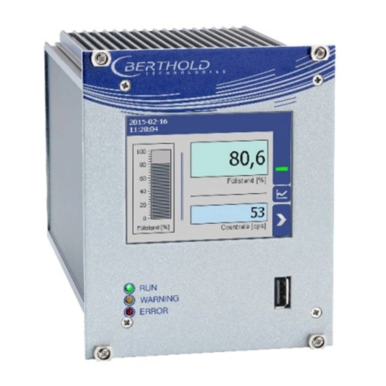
3 System Description LB 470 Level 3.3.1 S oftware 7 4 B The EVU is delivered with pre-installed software. The revision status (version) of the software can be seen on the screen display when starting up the EVU or in the menu "Device information"... - Page 21 3 System Description LB 470 Level 3.3.2 F ront/rear view master EVU 7 5 B Front view master EVU The following control elements are found on the front of the master EVU: • LEDs for status display of individual operating states •...
- Page 22 3 System Description LB 470 Level Status displays of the master EVU The LEDs (fig.1, items 2-4) below the touch display show the current operating sta- tus of the master EVU. Display LED Description RUN This LED lights up green if the device is in operation and fault-free.
-
Page 23: 5 B F Ront/Rear View Master Evu
3 System Description LB 470 Level Rear view master EVU The following connections are located on the back of the EVU: • Master/slave connector, 4-pin • RJ45 socket for Ethernet • 32-pin plug connector Master/slave 4-pin connector RJ45 socket for Ethernet 32-pin plug connector Fig. -
Page 24: 6 B F Ront/Rear View Slave Module
3 System Description LB 470 Level 3.3.3 F ront/rear view slave module 7 6 B The LEDs Rx and Tx are found on the front of the slave module. The LED Rx flashes green when data is received. The LED Tx flashes green when data is sent. The 32-pin plug connector is found on the back side. -
Page 25: Measurement Arrangements
3 System Description LB 470 Level Measurement arrangements The detector and/or the source are rod-shaped for a radiometric level measure- ment, so as to form a triangular or rectangular useful beam field. The change of the measurement signal for different level results from the different sized covering of the radiation field. - Page 26 3 System Description LB 470 Level Point source / shield Mounting base with source min / max level Radiation field Rod detector 1 + 2 Rod detector 1 + 2 (side view) Measurement line (1st detector - master EVU) Measurement line (2nd detector - slave module) Connection master EVU - slave module Master EVU Slave module...
- Page 27 3 System Description LB 470 Level Mounting base Rod source / shield Mounting base with source Min/max level Radiation field Upper marking groove Rod detector Lower marking groove Fig. 9 Schema Rod source - rod detector Mounting base Rod source / shield Mounting base with source Min/max level Radiation field...
- Page 28 3 System Description LB 470 Level Min / max level Point source in the dip tube Shield Radiation beam Detector Fig. 11 Schema point source - point detector (absorption level measurement) The detector and the source are usually formed as points in an absorption level measurement.
-
Page 29: Installation
The applicable national regulations of the country of use have to be observed! Repair and maintenance on the devices may only be performed by experts (see chapter 2.3). In case of doubt, the complete device must be returned to BERTHOLD for re- pair. NOTICE The Evaluation unit is not explosion protected and is not designed for hazardous environments. -
Page 30: Installation Variants
4 Installation LB 470 Level Installation variants The modules can be installed either in wall housings (Fig. 12) or 19" subracks (Fig. 13). Installation variants wall housing Fig. 12 Installation variants wall housing Installation Connection Components variant Terminal panel master 2 Master (Fig. - Page 31 4 Installation LB 470 Level Installation variants subrack Fig. 13 Installation variants 19" subrack with terminal panel Installation variant Connection Components 2 terminal panel master (Fig. 13, 4 Master item 1) 19" subrack 2 terminal panel master/slave (Fig. 2 Master, 6 13, item 2) Slaves Fig.
-
Page 32: 8 B I Nstallation In The Wall Housing
4 Installation LB 470 Level 4.3.1 I nstallation in the wall housing 7 8 B The wall housing may be equipped differently, depending on requirements (see chap. 4.3 Installation variants). To do this, a corresponding terminal panel is located in the wall housing. NOTICE The master EVUs / slave modules must be secured against pulling out by fixing screws (Fig. - Page 33 4 Installation LB 470 Level Installation of the modules (master-master) Master-slave connector Socket board Guide rails Fixing screws Fig. 16 Installation of the modules (master-master) Set modules into the guide rails and push it gently until the plug connector of the module (Fig. 16, item 2) is inserted into the socket board. Tighten all fixing screws (Fig.
- Page 34 4 Installation LB 470 Level Mounting the wall housing 4 holes (Fig. 17) are provided for mounting on the wall etc. Fig. 17 Mounting the wall housing Prepare the holes. Use adequately dimensioned mounting material. Screw the housing securely to the wall. NOTICE It is recommended that the wall housing be protected from direct sunlight in order to maintain maximum ambient temperature (see appendix “Technical...
-
Page 35: 9 B I Nstallation In The 19" Subrack
4 Installation LB 470 Level 4.3.2 I nstallation in the 19" subrack 7 9 B The 19" subrack can be equipped differently, depending on requirements (see chap. 4.3 Installation variants). The rear clamp blocks (Fig. 18, item 3) or terminal panels (Fig. - Page 36 4 Installation LB 470 Level Installation with clamp blocks j DANGER Danger to life from electric shock! Installation/maintenance may only be carried out if the device has been de-energised. Test of absence of harmful voltages when the front side is open. ...
- Page 37 4 Installation LB 470 Level Installed with terminal panels j DANGER Danger to life from electric shock! Installation/maintenance may only be carried out if the device has been de-energised. Test of absence of harmful voltages when the front side is open. ...
-
Page 38: Electric Installation
5 Electric Installation LB 470 Level Electric Installation General Instructions j DANGER Danger to life from electric shock! The installation may only be carried out by a qualified electrician. Please adhere to the relevant safety regulations. Open the housing only in a dry environment and for installation, mainte- ... -
Page 39: 0 B C Ircuit Breaker
(there and back) of 40 ohms. For standard cables from BERTHOLD TECHNOLOGIES (Id. no. 32024), this results in a cable length of 1000m, from the evaluation unit to the detector. For intrinsically safe systems, the maxi- mum permissible inductance and capacitance of the cable should be considered to the max. -
Page 40: 2 B C Able Glands And Blanking Elements
Cable bushings and blanking elements must comply with the applicable IP protection class and with the requirements for the operational environment. We recommend ordering missing cable glands, blanking elements or adapt- ers from BERTHOLD. 56925BA2 Rev. 03, 11/2017... -
Page 41: 3 B P Rotective Earth And Equipotential Bonding
5 Electric Installation LB 470 Level 5.1.4 P rotective earth and equipotential bonding 8 3 B The protective earth conductor has to be connected to the terminals marked with "PE". The housing must be connected to local equipotential bonding. ... -
Page 42: Electric Connection In The Wall Housing
5 Electric Installation LB 470 Level Electric connection in the wall housing j DANGER Danger to life from electric shock! The installation may only be carried out by a qualified electrician. Please adhere to the relevant safety regulations. Installation/maintenance may only be carried out if the device has been de- ... - Page 43 5 Electric Installation LB 470 Level Screw the the cable glands (Fig. 20, item 6) with the counternut cable glands (Fig. 20, item 7). NOTICE Apply the voltage of the specified and marked (Fig. 20, item 3) range only! NOTICE Note the specification relating to Cables, Protective earth, equipotential bond- ing and EIA-485 (RS-485) in chapter 5.1.
-
Page 44: Electrical Connection In A 19" Subrack With Terminal Board
5 Electric Installation LB 470 Level Electrical connection in a 19" subrack with terminal board j DANGER Danger to life from electric shock! The installation may only be carried out by a qualified electrician. Please adhere to the relevant safety regulations. ... - Page 45 5 Electric Installation LB 470 Level Variant master/master Supply Voltage Variant master/ 3x slave Voltage output Opening terminal connection Marking Supply Voltage Stripped wire RJ45 connector (network) Connection detector PE connection Fig. 21 Electrical connection in the 19" subrack NOTICE Apply the voltage of the specified and marked (Fig.
- Page 46 5 Electric Installation LB 470 Level Open the terminal connection (Fig. 21, item 3) with an operating tool (slot- ted screwdriver) and insert the stripped wire (min. 8 mm) (Fig. 21,item 4). The terminal connection closes by pulling out the operating tool. The terminal connections are designed for wires (flexible) with a conductor cross-section from 0.2 mm²...
-
Page 47: Terminal Board Master/Master
5 Electric Installation LB 470 Level Terminal board master/master Fig. 22 Terminal board master/master back side (Label A/B) 56925BA2 Rev. 03, 11/2017... - Page 48 5 Electric Installation LB 470 Level Pin assignment master/master Item Plug connectors Function DETECTOR MASTER – Connection LB 4700 or LB 44xx detector DETECTOR MASTER + MASTER/SLAVE GND MASTER/SLAVE TxD Connection of further slave units MASTER/SLAVE RxD MASTER/SLAVE RTS RELAIS 3 NC DIGITAL OUT RELAIS 3 COM RELAIS 2 NC...
-
Page 49: Terminal Board Master/Slave
5 Electric Installation LB 470 Level Terminal board master/slave Fig. 23 Terminal board master/slave back side (label A) 56925BA2 Rev. 03, 11/2017... - Page 50 5 Electric Installation LB 470 Level Pin assignment master/slave item Plug connectors Function DETECTOR MASTER – Connection LB 4700 or LB 44xx detector DETECTOR MASTER + DETECTOR SLAVE 1 – DETECTOR SLAVE 1 + DETECTOR SLAVE 2 – Connection of further slave units DETECTOR SLAVE 2 + DETECTOR SLAVE 3 –...
- Page 51 5 Electric Installation LB 470 Level DIGITAL IN 2 GND DIGITAL IN 2 IN Logic Input + 24 V 24 V out (max. 200 mA) NOTICE The connections master/slave A and master/slave B are identical. 56925BA2 Rev. 03, 11/2017...
-
Page 52: Electrical Connection In The 19" Subrack With Clamp Block
5 Electric Installation LB 470 Level Electrical connection in the 19″ subrack with clamp block j DANGER Danger to life from electric shock! The installation may only be carried out by a qualified electrician. Please adhere to the relevant safety regulations. ... - Page 53 5 Electric Installation LB 470 Level Clamping screw (M2.5) RJ45 connector (network) Opening terminal connection PE connection 4-pin master/slave plug (only master EVU) terminals 41-44 Fig. 24 Electrical connection in the 19″ component rack (Ex.: 1xMaster, 9xSlave) Connect the lines to the clamp blocks according to assignment (chap. 5.6.2 or 5.6.3).
-
Page 54: 4 B A Ssignment Terminals Master/Slave Plug
5 Electric Installation LB 470 Level NOTICE Note the specification relating to Protective earth and equipotential bonding in chapter 5.1.4. NOTICE Only cable that is suitable for connection to the corresponding terminals may be used. For further specifications, see appendix “Technical Information”. 5.6.1 A ssignment terminals master/slave plug 8 4 B... -
Page 55: 5 B A Ssignment Clamp Block Master Evu
5 Electric Installation LB 470 Level 5.6.2 A ssignment clamp block master EVU 8 5 B Signal Signal DETECTOR GND C - 2 A - 2 DETECTOR + not assigned C - 4 A - 4 not assigned not assigned C - 6 A - 6 not assigned... -
Page 56: 6 B A Ssignment Clamp Block Slave Module
5 Electric Installation LB 470 Level 5.6.3 A ssignment clamp block slave module 8 6 B Signal Signal DETECTOR SLAVE GND C - 2 A - 2 DETECT. SLAVE +15 V not assigned C - 4 A - 4 not assigned not assigned C - 6 A - 6... -
Page 57: Operation Of The Software
6 Operation of the Software LB 470 Level Operation of the Software System start Fig. 30 Start screen with display of the software version System start with invalid application software A different menu structure is present in this mode. Fig. 31 Start screen (Invalid application software) IMPORTANT The communication between the sensor and EVU is limited to 1200 baud. -
Page 58: Evu Standard Display
6 Operation of the Software LB 470 Level EVU standard display IMPORTANT Changing the language of the user interface is described in chapter 7.3.1 Sys- ten | Interface. Click on the blue field in order to switch the display between detector temperature (Fig. -
Page 59: Diagram Display
6 Operation of the Software LB 470 Level 6.3.1 Diagram display Clicking the diagram symbol (Fig. 32, item 5) changes the view to the diagram dis- play. The arrow keys (Fig. 34, item 1) are used to switch between the diagrams Level–... -
Page 60: 7 B E Vent Reports
6 Operation of the Software LB 470 Level 6.4.1 E vent reports 8 7 B Events are displayed in the standard display and in the submenus as a symbol. All events are displayed on the main screen. A specific “D” (for detector) indicates that a detector has an event, the prefix “M”... -
Page 61: Input Field
6 Operation of the Software LB 470 Level Click <Close> to return to the submenu or to the standard display. The icon disappears from the status information. IMPORTANT If you click the button <Close>, the event message is closed, the icon continues to be displayed. -
Page 62: Main Menu Device Setup
7 Main Menu Device Setup LB 470 Level Main Menu Device Setup Main Menu - Device Setup Identfification Chap. 7.1 Location Device Information Access Chap. 7.2 Setup Chap. 7.3 System Sensors Calibration Measurement Signal-Condition Detector Calibration Settings Date / Time Damping Configuration Calibrate... -
Page 63: Menu Identification
7 Main Menu Device Setup LB 470 Level Fig. 38 Menu "Device Setup" Menu identification Device Setup | Identification You can make the following settings and read information in the Identification menu: • Display and change the location name • Display of hardware and software information Fig. -
Page 64: 8 B L Ocation
7 Main Menu Device Setup LB 470 Level 7.1.1 L ocation 8 8 B Device Setup | Identification | Location The location of the evaluation unit is displayed (Fig. 39, item 1) in the Location menu. The name can only be edited (7.2 Menu Access) in the access level "Stand- ard". -
Page 65: 9 B D Evice Information
The secured settings should then be imported after the successful software update. The current software versions can be downloaded from the Berthold website (www.berthold.com). IMPORTANT In order for the system to detect the update file it must not be located in an index in the USB storage device. - Page 66 Measurement is interrupted. Click the Button <Restart> to reboot the EVU. NOTICE BERTHOLD TECHNOLOGIES recommends calibrating the current outputs when- ever a module has been installed/replaced or if a software update has been carried out. 56925BA2 Rev. 03, 11/2017...
-
Page 67: Menu Access
You can change all data necessary for operation (e.g. calibration). User Level Admin This user level is only intended for the system management by BERTHOLD. Automatic logout Activating the selection box (Fig. 42 item 1) au- tomatically resets the access level Standard to “Basic”... - Page 68 7 Main Menu Device Setup LB 470 Level Assign / change password To set or change a password, select "Standard" (Fig. 42, item 4) and click on <Change password> (Fig. 42, item 2) to open the input field. Text field Button <OK>...
-
Page 69: Menu Setup
7 Main Menu Device Setup LB 470 Level Menu Setup Device Setup | Setup Fig. 44 Menu "Setup" 7.3.1 S ystem (Date / Time, Interfaces, Units, Network, Reset) 9 0 B Device Setup | Setup | System Fig. 45 Submenu "System" 56925BA2 Rev. - Page 70 7 Main Menu Device Setup LB 470 Level Set Date and Time Device Setup | Setup | System | Date / Time IMPORTANT The date and time must always be set correctly so that all records (log files) have the correct metadata. The correct date is also indispensable for the decay compensation.
- Page 71 7 Main Menu Device Setup LB 470 Level Interfaces Device setup | Setup | System | interfaces You can adjust the following settings in the submenu ″Interfaces″ (Fig. 47): • Local Display • Brightness / Touch • Input / Output •...
- Page 72 7 Main Menu Device Setup LB 470 Level Brightness / Timeout Device Setup | Setup | System | interfaces | Local Display | Brightness / Timeout Input field ″Time out″ Input field ″Dimming″ Input field Display switch off ″Time out″ Input field Display switch off ″Dimming″...
- Page 73 7 Main Menu Device Setup LB 470 Level Input / Touch Device Setup | Setup | System | Interfaces | Local Display | Input / Touch | Calibrate Touchscreen The mouse pointer automatically becomes visible when a mouse is inserted into the USB port.
- Page 74 7 Main Menu Device Setup LB 470 Level Repeat the process until the cross is no longer displayed and the calibration is finished. Confirm the calibration by clicking on the white screen to go back to "In- put/Touch" Execute a restart of the EVU after prompting. Language Device Setup | Setup | System | interfaces | Language 1 Selection arrow...
- Page 75 7 Main Menu Device Setup LB 470 Level CE Remote Control Device Setup | Setup | System | interfaces | Remote Control By activating (Fig. 53, item 1) the CE Remote Control, the unit can be operated via the network connection. The software of the remote control (RC software) is stored on the device and can be copied to a USB storage device.
- Page 76 7 Main Menu Device Setup LB 470 Level Units Device Setup | Setup | System | Units Clicking on the individual selection arrow lists the available units for the measuring value. The selected unit is shown in the standard display. Selection ″PV Format″...
- Page 77 7 Main Menu Device Setup LB 470 Level Network Device Setup | Setup | System | Network In the Network settings submenu, you can make changes to the network settings. The information can only be edited in the access level "Standard" (see chap. 7.2 Menu Access).
- Page 78 7 Main Menu Device Setup LB 470 Level Remote Control Software If the EVU is connected to a network at the RJ45 socket (Fig. 3, item 2), the EVU can be operated via a computer. The software can be loaded onto a USB storage device (see Chapter “CE Remote Control”).
- Page 79 7 Main Menu Device Setup LB 470 Level Reset Device (evaluation unit) Device settings | Setup | System | Reset Device The evaluation unit can be restarted and reset to factory settings in the submenu "Reset device". Button Reboot Button Factory settings Window "Warning: Reboot"...
- Page 80 7 Main Menu Device Setup LB 470 Level Reset device (Factory Reset) IMPORTANT When there is a reset to factory settings, all data logs are deleted and all user- defined configuration settings are reset! To reset the evaluation unit to the factory settings, click the button <Factory settings>...
-
Page 81: 1 B S Ensors
7 Main Menu Device Setup LB 470 Level 7.3.2 S ensors 9 1 B Device settings | Setup | Sensors You can perform the following settings and read information in the submenu Sen- sors: • Detector configuration (Fig. 58, item 1) o Add / Remove detectors o Settings of the detectors •... - Page 82 7 Main Menu Device Setup LB 470 Level Detector configuration Device settings | Setup | Sensors | Detector configuration In the sub-menu “Detector configuration” the detectors for the measuring system are added and configured. Only configured detectors are listed and shown in the menu (Fig.
- Page 83 7 Main Menu Device Setup LB 470 Level Detector Settings The settings of a configured detector are edited by selecting and clicking on <Edit> (Fig. 59, item 3). IMPORTANT For systems with a single detector, window A is displayed. For cascaded sys- tems, window B is displayed.
- Page 84 7 Main Menu Device Setup LB 470 Level Configure a cascaded system Note the arrangement of the system components during configuration (see chap- ter 3.2 Measuring Principle). Selection box “Cascaded measurement” Button <Search> Button < + > Window “Search detectors” Button <Edit>...
- Page 85 7 Main Menu Device Setup LB 470 Level Detector settings Device settings | Setup | Sensors | [NAME DETECTOR] You can adjust the following settings and read information in the submenu of the respective detector: • Overview of count rate, HV value and temperature •...
- Page 86 7 Main Menu Device Setup LB 470 Level Detector settings: Overview Device settings | Setup | Sensors | [NAME DETECTOR] | Overview All important parameters and measured values of the detector are clearly displayed in the submenu "Overview". Status information of the detector Device ID Live rate [cps] HV mode...
- Page 87 "Plateau" (Fig. 64) leads to the plateau measuring and the display of plateau val- ues. Please contact your responsible service or sales partner, or Berthold directly, so that they can get a qualified assessment to the measured plateau. Fig. 64 Menu "Plateau"...
- Page 88 Plateau Settings Device settings | Setup | Sensors | [NAME DETECTOR] | Plateau | Plateau settings The values in the submenu "Plateau settings" are pre-set by Berthold on delivery and can be used in most situations. You have the following settings options in the submenu "Plateau Settings": HV start / HV stop Defining the range of the plateau recording.
- Page 89 7 Main Menu Device Setup LB 470 Level Perform Plateau Measurement Device settings | Setup | Sensors | [NAME DETECTOR] | Plateau | Plateau Measure- ment IMPORTANT The environmental conditions and the dose rate must be constant during the plateau recording. Observe the operating manual of the detector! Plateau curve Notice Maintenance...
- Page 90 7 Main Menu Device Setup LB 470 Level The information (Fig. 66, item 6 - 8) from the plateau measurement are dis- played in the status information. The LED Run flashes on the EVU during the plateau measurement. The LED "Warning" LED lights up at the same time. If you click on the <...
- Page 91 7 Main Menu Device Setup LB 470 Level Plateau Curve Device settings | Setup | Sensors | [NAME DETECTOR] | Plateau | Plateau Curve The mapped characteristic curve (Fig. 68, item 2) of the last complete plateau meas- urement is displayed in the submenu "Plateau curve". Date and Time of measurement recording Characteristic curve Fig.
- Page 92 7 Main Menu Device Setup LB 470 Level Detector settings: Temperature Device settings | Setup | Sensors | [NAME DETECTOR] | Temperature The current temperature and the extreme values of the detector is displayed in the submenu "Temperature". Current temperature of the detector [°C] Maximum measured temperature [°C] Minimum measured temperature [°C] Fig.
- Page 93 7 Main Menu Device Setup LB 470 Level Detector settings: High Voltage | Detector Type Device settings | Setup | Sensors | [NAME DETECTOR] | High Voltage | Detector Type Internal device parameters are adjusted to suit the size of the used scintillator by setting the detector code.
- Page 94 7 Main Menu Device Setup LB 470 Level NOTICE Default HV is preset by BERTHOLD. A subsequent change is not usually neces- sary. The default value HV = 0 may only be set for testing purposes. An incorrect setting may cause malfunction.
- Page 95 7 Main Menu Device Setup LB 470 Level Detector settings: Detector Service Device settings | Setup | Sensors | [NAME DETECTOR] | Detector Service You can adjust the following settings and read information in the submenu "Ser- vice": • Device information •...
- Page 96 (Fig. 74, item 4) button can be clicked. Click on the button <Firmware Update> (Fig. 74, item 4). The update is performed. NOTICE Berthold recommends a test or a calibrating the current outputs whenever if a software update has been carried out. 56925BA2 Rev. 03, 11/2017...
- Page 97 7 Main Menu Device Setup LB 470 Level Detector settings: Service | Event Log Device settings | Setup | Sensors | [NAME DETECTOR] | Detector Service | Event Log The last 25 events of the detector are displayed in the submenu "Event Log". Date / time of the event Event no.
- Page 98 7 Main Menu Device Setup LB 470 Level With the button <Close>, close the event description (Fig. 76, item 7). With the button <Clear event log> (Fig. 77, item 2) all events are deleted. Detector settings: Detector Service | Event Overview Device settings | Setup | Sensors | [NAME DETECTOR] | Detector Service | Event Over- view All events that can be logged are chronologically presented in tabular form in the...
- Page 99 7 Main Menu Device Setup LB 470 Level Detector settings: Detector Service | Reset Detector Device settings | Setup | Sensors | [NAME DETECTOR] | Detector Service | Reset De- tector In the submenu ″Reset Detector″, the detector can be restarted and be reset to the factory settings.
-
Page 100: 2 B C Alibration
Errors in calibration or in the parameter setting can lead to incorrect measure- ment results. This may possibly lead to loss of production or to damage in the system. We encourage you to have the calibration and commissioning performed by Berthold service. Fig. 79 Menu "Calibration" 56925BA2 Rev. 03, 11/2017... - Page 101 7 Main Menu Device Setup LB 470 Level Basic Setup Device Setup | Setup | Calibration | Basic Setup Checkbox "Inverted Curve" Calibration "1 Point Exp." Selection calibration Type Calculation "2 Point Exp." Calculation "Linear" Fig. 80 Basic Setup Calibration method The method by which the measuring system must be calibrated depends on the respective measuring arrangement.
- Page 102 7 Main Menu Device Setup LB 470 Level Calibration Settings: Background Device settings | Setup | Calibration | Calibration Settings The background count rate (Fig. 82, item 1) indicates the natural background radi- ation of the detector, if no radiation source is installed. This count rate is compensated for by the system.
- Page 103 7 Main Menu Device Setup LB 470 Level IMPORTANT All entries and changes in the ″Parameters″ tab will take effect only when you click on the < Calibrate > button click in the Calibrate Submenu. Input field Background [cps] Button <Ok>...
- Page 104 7 Main Menu Device Setup LB 470 Level Calibration Settings: Nuclide Device settings | Setup | Calibration | Calibration Settings The isotope used can be selected in the ″Nuclide″ tab. The half-life of the isotope is shown on the display field (Fig. 83, item 1). Display field half-life [years] Selection arrow Nuclide Selection Caesium-137...
- Page 105 7 Main Menu Device Setup LB 470 Level Calibration Settings: Table (linear calibration type) Device settings | Setup | Calibration | Calibration Settings Table calibration Count of the calibration points (e.g. 2 of max. 11) Button <Edit> Measuring Duration [s] Button Add measuring point <...
- Page 106 7 Main Menu Device Setup LB 470 Level Calibration Settings: Table (2 Point Exp. calibration type) Device settings | Setup | Calibration | Calibration Settings Table calibration Count of the calibration point Button <Edit> Read-In Time [s] Button Add measuring point <...
- Page 107 7 Main Menu Device Setup LB 470 Level Calibration Settings: Table (1 Point Exp. calibration type) Device settings | Setup | Calibration | Calibration Settings The absorption coefficient, the measuring path and the product density must be known. The second calibration point is thereby calculated. Table calibration Count rate [cps] Button...
- Page 108 7 Main Menu Device Setup LB 470 Level Calibration Settings: Chart Device settings | Setup | Calibration | Calibration Settings The characteristic curve of the calibration performed is shown in the tab ″Chart″. Axis level [%} Axis count rate [cps] Characteristic chart (exponential) Characteristic chart (linear) Fig.
- Page 109 7 Main Menu Device Setup LB 470 Level Calibrate Device settings | Setup | Calibration Data that are necessary for a complete measurement are found in the calibration parameter set. All the data of the calibration parameter set are transferred to the measurement parameter set when the button "Calibrate"...
- Page 110 7 Main Menu Device Setup LB 470 Level Recall Device settings | Setup | Calibration | Recall Button <Recall> Window ″Recall measurement to parameter set″ Fig. 90 Recall Recall to calibration set Click on the button < Recall > if you want to copy the measurement set into the calibration set.
- Page 111 7 Main Menu Device Setup LB 470 Level Adjust: Standard Adjust Device settings | Setup | Calibration | Adjust Use the functionality after source exchange or after entering a theoretical, normal- ized multi-point calibration (e.g. a Radical calculation) to adjust the table in the measuring set.
- Page 112 7 Main Menu Device Setup LB 470 Level Click on the field "Process value" (Fig. 92, item 3) to open the input field. Enter the process value % (acc. to standard display) and confirm. Click on the ″Read-In-Time″ field (Fig. 92, item 2) and specify the duration of measurement in seconds.
- Page 113 7 Main Menu Device Setup LB 470 Level Adjust: Low Level Adjust Device settings | Setup | Calibration | Adjust After calibration, a level adjustment can be performed. A level adjustment must be performed if the level shown is not the actual level. The lower adjustment can only be performed at a level <...
- Page 114 7 Main Menu Device Setup LB 470 Level more accurate the result. Click on the button < Perform adjust now > (Fig. 94, item 1). A new window opens. Click on the button < Start > (Fig. 94, item The measurement starts.
- Page 115 7 Main Menu Device Setup LB 470 Level Adjust: High Level Adjust Device settings | Setup | Calibration | Adjust The upper adjustment can only be performed at a level > 50%. The count rate at 0% will be kept fixed, while all other points of the curve will be adjusted according to the adjusted count rate at the entered level value.
- Page 116 7 Main Menu Device Setup LB 470 Level Click on the < Start > button (Fig. 96, item 5). The measurement starts. Click < Ok > to accept the value. The level has been adjusted to the process value (see standard display). ...
- Page 117 GPC example measurement arrangement NOTICE This functionality presuppose comprehensive knowledge and should only be ac- tivated by a Berthold service technician or a specially trained and instructed person. You can make the following settings in the submenu GPC (gas properties compen- sation) (Fig.
- Page 118 7 Main Menu Device Setup LB 470 Level NOTICE An additional compatible Berthold probe for measuring the gas density is ab- solutely necessary for the gas properties compensation. The probe is connected to the level measurement via the slave interface.
- Page 119 7 Main Menu Device Setup LB 470 Level 56925BA2 Rev. 03, 11/2017...
- Page 120 7 Main Menu Device Setup LB 470 Level GPC calibration: Reference count rate NOTICE To determine the reference count rate of the GPC detector, there must be a constant gas density (calibration conditions) in the container. Input field count rate [cps] Input field measuring Duration [s] Button <...
- Page 121 7 Main Menu Device Setup LB 470 Level GPC calibration: Background The background count rate (Fig. 99, item 3) indicates the natural background radi- ation of the gas density detector if no radiation source is installed. This count rate is compensated for by the system. Input field count rate [cps] Input field measuring Duration [s] Button...
- Page 122 7 Main Menu Device Setup LB 470 Level GPC calibration: Factor M For complex applications, differences in geometry between level measurement and density measurement may exist and/or highly different absorption coefficients (e.g. by different nuclides) may occur. In this case, an adjustment for at least 2 (up to 10) different gas densities is necessary to determine the manual correction factor (M).
- Page 123 7 Main Menu Device Setup LB 470 Level Calculate Factor M The "Factor M" (Fig. 102, item 2) is close to 1 (default value) for standard applica- tions. Click the button < Calculate > (Fig. 102, item 3) to determine Factor M from the count rate.
- Page 124 7 Main Menu Device Setup LB 470 Level Reset GPC Settings Device settings | Setup | Calibration | GPC | Reset GPC All GPC settings can be reset in the submenu ″Reset GPC Settings″. Button <Reset GPC settings> Window “Reset Warning” Fig.
-
Page 125: 3 B M Easurement
7 Main Menu Device Setup LB 470 Level 7.3.4 M easurement 9 3 B Device settings | Setup | Measurement The submenu ″Measurement″ is used for an overview of the measurement param- eters and calibration settings used. Measurement: Parameter The parameters used for the current measurement are displayed in the ″Parame- ters″... - Page 126 7 Main Menu Device Setup LB 470 Level Measurement: Chart The characteristic curve of the current measurement is displayed in the ″Graphics″ tab. Axis level [%} Axis count rate [cps] Characteristic curve Fig. 107 Measurement (Chart) 56925BA2 Rev. 03, 11/2017...
-
Page 127: 4 B S Ignal Condition
7 Main Menu Device Setup LB 470 Level 7.3.5 S ignal Condition 9 4 B Device settings | Setup | Signal Condition You can perform the following settings and read information in the "Signal Con- dition" submenu: • Damping (time constant) •... - Page 128 7 Main Menu Device Setup LB 470 Level Signal Condition: PV Range Device settings | Setup | Signal Condition | PV Range The lower and upper limit of the process range of the active measuring parameter set can be set in the tab “PV Range” (Process Value Range). These limits define the signal range of the analog current output (4 ...
- Page 129 7 Main Menu Device Setup LB 470 Level Signal Condition: Rapid Switch Device settings | Setup | Signal Condition | Rapid Switch IMPORTANT The use of the function "Rapid Switch" is recommended only for special appli- cations where the output signal has to adapt rapidly to the new value, e.g. in case of measurements on small tanks and if sudden level changes occur.
- Page 130 7 Main Menu Device Setup LB 470 Level Signal processing: XIP (Radiation Interference) Device settings | Setup | Signal Condition | XIP This function allows you to take interference (XIP) into consideration. Measure- ment jumps that influence the process can arise through interference. Only rapid increases are considered.
- Page 131 7 Main Menu Device Setup LB 470 Level Signal processing: Source replacement Device settings | Setup | Signal Condition | Source replacement Notification for a source replacement can be activated in this submenu. The maintenance message ″Replace source″ when this date is reached. NOTICE For radiation protection reasons, a source replacement is recommended after 15 years.
-
Page 132: 5 B I Nputs
7 Main Menu Device Setup LB 470 Level 7.3.6 I nputs 9 5 B Device settings | Setup | Inputs The two digital inputs (DI) can be set, as well as displaying the DI status, in the submenu Inputs. Fig. 114 Menu "Inputs"; Submenu "Digital inputs (DI) " 56925BA2 Rev. - Page 133 7 Main Menu Device Setup LB 470 Level Digital inputs (DI) Assignment Device settings | Setup | Inputs | Digital Inputs | Assignment The menu Assignment determines which function is executed when the digital in- put is switched. In the "ACTIVE" state, the selected function is executed. The active state is initiated by closing the digital input.
- Page 134 7 Main Menu Device Setup LB 470 Level DI State Device settings | Setup | Inputs | Digital Inputs | DI State The states of the two digital inputs are displayed in the submenu ″DI State″. DI Input 1 state (ACTIVE / PASSIVE) DI Input 2 state (ACTIVE / PASSIVE) Fig.
-
Page 135: 6 B O Utputs
7 Main Menu Device Setup LB 470 Level 7.3.7 O utputs 9 6 B Device settings | Setup | Outputs You can make the following settings and read information in the submenu "Out- puts": • Analogue Output Mapping (AO) o Function o AO monitoring o Failure mode o Current limits... - Page 136 7 Main Menu Device Setup LB 470 Level Fig. 118 Submenu "Analog Output" Analogue output: AO Mapping Device settings | Setup | Outputs | Analogue Output (AO) | AO Mapping A function can be assigned to an analogue output in the submenu ″AO Mapping″. The current output signal is between 4 mA and 20 mA.
- Page 137 7 Main Menu Device Setup LB 470 Level Analogue output: AO Monitoring Device settings | Setup | Output | Analogue Output (AO) | AO Monitoring If ″AO Monitoring" is activated (Fig. 120, item 1), the current output will be moni- tored.
- Page 138 7 Main Menu Device Setup LB 470 Level Analogue output: AO Failure Mode Device settings | Setup | Output | Analog Output (AO) | AO Failure Mode The alarm function is set when an error is detected at the current output in the submenu ″Error mode″.
- Page 139 7 Main Menu Device Setup LB 470 Level Analogue output: AO Limits Device settings | Setup | Output | Analog Output (AO) | AO Limits By clicking on the input fields (Fig. 122, item 1, item 2), the values [mA] for the lower and upper current limit can be set.
- Page 140 For calibration of the current output, an ammeter (not included in the scope of delivery) is required, which is connected to the current output. NOTICE BERTHOLD TECHNOLOGIES recommends calibrating the current outputs when- ever a module has been installed/replaced or if a software update has been carried out.
- Page 141 7 Main Menu Device Setup LB 470 Level Perform calibration Connect the measuring lines of the current measuring device on the back of the EVU to the analog output. Observe the terminal allocation in Chapter 5.4 and 5.5 for executions with connection boards (Fig.
- Page 142 7 Main Menu Device Setup LB 470 Level Digital Outputs (DO) Device settings | Setup | Output | Digital Outputs (DO) The signals of the digital outputs are switched via potential-free relay contacts. The contacts are controlled "fail safe", ie, in the event of an alarm, the current at the relay coil drops and the NO contact (normally open) is opened.
-
Page 143: 7 B A Larms
7 Main Menu Device Setup LB 470 Level 7.3.8 A larms 9 7 B Device settings | Setup | Alarms You can make the following settings and read information in the submenu "Alarms": Fig. 125 Menu "Alarms" PV Alarm Behaviour Device Setup | Setup | Alarms | PV Alarm Behaviour... - Page 144 7 Main Menu Device Setup LB 470 Level PV Alarm Settings Device settings | Setup | Alarms | PV alarm settings You can set the values for the level alarms (max. and min.) and the hysteresis of these in the submenu ″PV Alarm Settings″. When exceeding or falling below the switching point, an event message appears in the status display.
- Page 145 7 Main Menu Device Setup LB 470 Level Det.-Temp. Alarm Behaviour Device settings | Setup | Alarms | Det.-Temp. Alarm Behaviour The behaviour in case of alarm (NE107 status) can be set for the detector temper- ature in the submenu ″Det.-Temp. Alarm Behaviour ″. Selection arrow NE107 Status Selection ″No Status″...
- Page 146 7 Main Menu Device Setup LB 470 Level Detector Temperature Alarm Settings Device settings | Setup | Alarms | Det.-Temp. Alarm Settings The values for the detector temperature (max. and min.) can be set in the submenu ″PV Det.-Temp. Alarm Settings″. When there is exceeding or falling below the switching point, an event message appears in the status display.
-
Page 147: 8 B S Imulation
7 Main Menu Device Setup LB 470 Level 7.3.9 S imulation 9 8 B Device settings | Setup | Simulation A check for the following functions can be performed in the submenu ″Simulation″: Fig. 130 Menu "Simulation" NOTICE When starting a simulation, the measurement is stopped and a status message appears. - Page 148 7 Main Menu Device Setup LB 470 Level Simulation Analog Output Device settings | Setup | Simulation | Analog Output Input field ″Nominal″ Display field ″Feedback″ [mA] Button < Disable Test Mode > Fig. 131 Simulation Analog Output Click on the input field (Fig. 131, item 1) and enter the target value for the simulation.
- Page 149 7 Main Menu Device Setup LB 470 Level Simulation Digital Output Device settings | Setup | Simulation | Digital Output 1 2 3 ERROR (DO-1) ALARM (DO-2) ALARM (DO-3) Dropdown field Button <Disable test mode> Fig. 132 Simulation Digital Outputs Click on the dropdown field (Fig.
- Page 150 7 Main Menu Device Setup LB 470 Level Simulation Count Rate Device settings | Setup | Simulation | Count Rate Input field Dampened count rate Button <End test mode> Fig. 133 Simulation Count Rate Click on the input field (Fig. 133, item 1) and enter count rate for the simula- tion.
-
Page 151: Menu Backup/Restore
7 Main Menu Device Setup LB 470 Level Menu Backup/Restore Device settings | Backup/Restore You can make a backup copy of the configuration data, and perform a recovery in the submenu Backup/Restore. Fig. 134 Menu "Backup/Restore" 7.4.1 Backup Device settings | Backup/Restore | Backup Button <Backup>... - Page 152 7 Main Menu Device Setup LB 470 Level The window ″Enter description″ appears. The message ″Error free″ (Fig. 135, item 3) appears in the field ″Backup data″ for error-free backup files. Click the button <Edit>, enter a description, and confirm with the Enter key. Click on the button <Save>.
-
Page 153: 0 0 B R Estore
7 Main Menu Device Setup LB 470 Level 7.4.2 R estore 1 0 0 B Device settings | Backup/Restore | Restore ″previous″ Button < Number of recovery files on the USB storage device ″next″ Button > Button <Restore> Recording date of the backup file Time of backup file recording Information about the backup data (error / error free) Confirmation window... -
Page 154: Main Menu Diagnostics
8 Main Menu Diagnostics LB 470 Level Main Menu Diagnostics Fig. 137 Menu "Diagnostics" Transmitter Temperature Diagnostics | Transmitter Temperature Temperature values from the evaluation unit (processor) are displayed in the menu item ″Transmitter Temperature″. Minimal extreme value [°C] Maximum extreme value [°C] Feedback [°C] Fig. -
Page 155: Events
8 Main Menu Diagnostics LB 470 Level Events Diagnostics | Transm. Events Fig. 139 Menu "Transm. Events" Information Events of the respective detector can be seen at Device settings | Setup | Sensors | [NAME OF DETECTOR] | Detector Service. 8.2.1 E VU event Log 1 0 1 B E V U E E E... - Page 156 8 Main Menu Diagnostics LB 470 Level Display event description Button <?> Button <Clear event log> Highlighted event Event no. Event title Event description Button <Close> Fig. 141 display an event log Click on a line in the list (Fig. 141, item 3). Click on <? >...
-
Page 157: 0 2 B T Ransm. Event Overview
8 Main Menu Diagnostics LB 470 Level 8.2.2 T ransm. Event Overview 1 0 2 B Diagnostics | Transm. Events | Transm. Event Overview All events that can be logged are chronologically presented in tabular form in the submenu "Event overview". Activate the check box ″Non-zero Counter only 0″ (Fig. 142, item 5) in order to display events that have occurred. -
Page 158: Change Log
8 Main Menu Diagnostics LB 470 Level Change Log Diagnostics | Change Log You can track changes that were performed on the device in the submenu ″Change log″. Time of the change Short info of the change Old state New state Fig. -
Page 159: Menu Data Log
8 Main Menu Diagnostics LB 470 Level Menu Data Log Diagnostics | Data Log You can set the log interval as well as delete and export the log data in the sub- menu ″Data log″. IMPORTANT The data cannot be viewed on the EVU Display or via Ethernet. The data must be exported to a USB storage device to view it on a PC. - Page 160 8 Main Menu Diagnostics LB 470 Level Export log data Click on the button <Stop> (Fig. 144, item 2) to stop the data log process. Connect a USB storage device to the device (Fig. 3, item 5). Click on the button <Export>...
-
Page 161: Export Service Data
8 Main Menu Diagnostics LB 470 Level Export service data Diagnostics | Export Service Data < > Button Export service data Process window Confirmation message Fig. 146 Export Service Data Connect a USB storage device to the device (Fig. 3, item 5). The USB storage is recognised by the system after a few seconds and the but- <Export service data>... -
Page 162: Troubleshooting
9 Troubleshooting LB 470 Level Troubleshooting Error Search Problem Cause Measure Check power supply and Master unit: Screen black; LEDs EVU does not work are not illuminated fuses Check cabling, contact Slave module: Slave module not clamped LEDs are not illuminated properly sockets Check the functioning of... - Page 163 9 Troubleshooting LB 470 Level Error search (continued) Check ID of the detector Detector is not detected (software) Incorrect ID in the configu- (see type plate on the de- ration tector) Restart EVU Touch panel does not respond Error in operating system ...
-
Page 164: Error Codes Of The Evaluation Unit
WD Reboot event occurs repeatedly. Check, if mas- sive electromagnetic interferences have caused this event. Watchdog malfunction. Contact M105 WD Failure Berthold service, if this event occurs re- peatedly. Watchdog is inactive. Activate Watch- M106 WD Off 56925BA2 Rev. 03, 11/2017... - Page 165 Software Reboot The device was restarted by user input. Failure of the external real time clock. M115 Extern RTC malfunction Contact Berthold service, if this event occurs repeatedly. The date could not be verified at M116 Corrupt Date startup. Check date and time and set if necessary.
-
Page 166: 0 4 B A Pplication
Default parameter set with default parameters. Calibrate de- vice Decay compensation failed. Contact M302 Decay compensation Berthold service, if this event occurs re- peatedly. Detector temperature at / below lower M303 Det Temp LL failure limit. Detector temperature at / above upper... -
Page 167: 0 5 B D Etector
Lost connection to at least one detector. Check detector settings and connections. D501 Detector not found It is recommend to have the device checked by Berthold Service, even if it seems to work normally. Temporarily lost connection to at least one detector. Check detector settings D502 Detector comm. - Page 168 No action necessary. The device M703 Software update automatically returns to measuring mode after the software update is fin- ished. Internal software failure. Restart the de- M799 Internal program error vice. Contact Berthold service, if this event occurs repeatedly. 56925BA2 Rev. 03, 11/2017...
-
Page 169: Maintenance And Repair
Repair and servicing on the EVU may only be carried out by experts (see chap- ter 2.3). In case of doubt, the complete EVU is to be sent to BERTHOLD. NOTICE Repair on electronic circuits on the circuit boards of a field device may only be carried out in the manufacturer's factory. -
Page 170: Replacing Of Fuses
10 Maintenance and Repair LB 470 Level 10.1 Replacing of Fuses j DANGER Danger to life from electric shock! Replacing of fuses may only be carried out by a qualified electrician. Please adhere to the relevant safety regulations. Installation/maintenance may only be carried out if the device has been ... - Page 171 10 Maintenance and Repair LB 470 Level Replacing fuse in the master module Fixing screws Fuse 250V 1A T (5x20 mm) screws Base Housing Fuse 250V TR5 T80mA (Ø 8,5 mm) Covering fuse Fig. 147 Replacing fuses master EVU De-energise the device. Loosen the four fixing screws (Fig.
- Page 172 10 Maintenance and Repair LB 470 Level Replacing fuse in the slave module Fixing screws Screws Housing Base Fuse Covering fuse Fig. 148 Exchange fuses slave EVU De-energise the device. Loosen the four fixing screws (Fig. 148, item 1) and remove the slave module from the wall housing or subrack.
-
Page 173: Cleaning
10 Maintenance and Repair LB 470 Level 10.2 Cleaning NOTICE Damage to the touch display! Solvents and abrasive additives can damage the touch display. Only clean the touch display with a wet cloth. • Only clean the EVU with a dry cloth or a dusting brush. •... -
Page 174: Decommissioning
11 Decommissioning LB 470 Level Decommissioning j DANGER Danger to life from electric shock! Decommissioning may only be carried out by qualified electricians. Please adhere to the relevant safety regulations. Decommissioning may only be carried out if the device has been de-ener- ... -
Page 175: Decommissioning Wall Housing
11 Decommissioning LB 470 Level 11.1 Decommissioning wall housing Fixing screws Connecting Terminals Locking Cable gland RJ45 connector (network) Mounting screws Fig. 149 Decommissioning wall housing Make sure that the locking bolts (Fig. 149, item 1) of all modules are tight- ened in order to prevent slipping. -
Page 176: Decommissioning 19" Subrack
11 Decommissioning LB 470 Level 11.2 Decommissioning 19" subrack RJ45 connector (network) PE cable Clamps terminal board Screw Connections Clamp blocks Fig. 150 Decommissioning wall housing De-energise the device. Remove the network plug (Fig. 150, item 1). Remove all lines from the terminal board (Fig. 150, item 2) or the clamp blocks (Fig. -
Page 177: Disposal Of Measurement System
11 Decommissioning LB 470 Level 11.3 Disposal of Measurement System j CAUTION Toxic! The product contains electronic components containing toxic substances that are harmful to health. Disposal is to be carried out in accordance with the disposal regulations via a disposal expert. -
Page 178: Appendix
12 Appendix LB 470 Level Appendix 12.1 Setup Protocol General data Date Measuring point Source No. Number of dectors LB44x LB47x LB54x Activity Isotope Cs-137 Co-60 Container Product Cascaded measurement Device configuration Model Installation variant Wall housing Subrack Anschluss Platine Clamp block Power supply 100-240V AC... - Page 179 12 Appendix LB 470 Level Setup Protocol (Continued) Parameters Password Language CE Remote Control enabled Network DHCP aktiv IP Adress Subnet Ggateway DNS-Server MAC Adress Calibration Linear Exponential inverted Curve Characteristic enabled Cs-137 Co-60 Damping time constant Process Value Range min.
- Page 180 12 Appendix LB 470 Level Setup Protocol (Continued) Parameters Digital Out- Function DO-2 Function DO-3 puts none none Low level alarm Low level alarm High level alarm High level alarm Det. temperature alarm Det. temperature alarm Rad. interference alarm Rad. Interference alarm Source Replacement Alarm Source replacement alarm Measurement stopped...
- Page 181 12 Appendix LB 470 Level 56925BA2 Rev. 03, 11/2017...
- Page 182 Modifications due to technical advancement reserved. © BERTHOLD TECHNOLOGIES GmbH & Co. KG Language: English Printed in Germany 11/2017 Rev. no.: 03 BERTHOLD TECHNOLOGIES GmbH & Co. KG Calmbacher Str. 22 75323 Bad Wildbad Germany www.Berthold.com Id.-No. 56925BA2...
- Page 183 Unité d'évaluation Détecteurs LB 47x LB 4700 Informations sur la sécurité 56925BA59 Rev. No.: 01, 11/2017...
- Page 185 BERTHOLD TECHNOLOGIES GmbH & Co. KG Calmbacher Str. 22 75323 Bad Wildbad, Germany www.Berthold.com Telephone +49 7081 177-0 Fax +49 7081 177-100 industry@Berthold.com...
- Page 186 1 A propos de ce manuel d’utilisation LB 470 Niveau Level A propos de ce manuel d’utilisation Avertissement Les avertissements sont identifiés comme suit : Signalement Source et conséquence Explication si requise Prévention En cas de danger • Symboles d’alerte : (triangle d’alerte) attire l’attention sur le risque.
- Page 187 1 A propos de ce manuel d’utilisation LB 470 Niveau Level RECOMMANDATION Si cette information n’est pas appliquée, un dysfonctionnement et/ou un dégât matériel peuvent apparaître. IMPORTANT Les sections identifiées avec ce symbole signalent des informations importantes du produit ou de son fonctionnement. Fournit des conseils sur l’application ou d’autres informations utiles.
- Page 188 1 A propos de ce manuel d’utilisation LB 470 Niveau Level 1.8.2 Symboles utilisés sur l’appareil Lire le manuel d’utilisation Veuillez suivre les instructions dans ce manuel d’utilisation. Décharge électrostatique Veuillez noter les instructions de manipulation. Composants sensibles aux décharges électrostatiques. Veuillez suivre les instructions de ce manuel d’utilisation.
- Page 189 Conformité La société BERTHOLD déclare par la présente, sous son entière responsabilité, que la conception de ce produit mis sur le marché par BERTHOLD est conforme aux directives EU indiquées dans la déclaration de conformité originale. Cette disposition devient nulle en cas de modifications non autorisées par Berthold ou dans le cas d’une utilisation impropre.
- Page 190 1 A propos de ce manuel d’utilisation LB 470 Niveau Level 56925BA59 Rev. 01, 11/2017...
- Page 191 ! • Suivre les instructions de sécurité mentionnées ! faire • Effectuer les opérations de maintenance prescrites ou les réaliser pour vous ! • Utiliser uniquement les accessoires et pièces de rechange BERTHOLD. 56925BA59 Rev. 01, 11/2017...
- Page 192 • Manoeuvre inappropriée ou oubli des équipements de sécurité présents. BERTHOLD assume la responsabilité de la garantie seulement dans le cadre de ses spécifications publiées. Si le produit est utilisé dans des conditions autres que celles décrites dans le présent manuel, la sécurité...
- Page 193 Les personnes autorisées sont celles désignées pour les tâches correspondantes dans le cadre de dispositions réglementaires, ou celles dûment autorisées par BERTHOLD pour des tâches particulières. Lors de la mise en œuvre de matières radioactives, la personne compétente en radioprotection doit être consultée...
- Page 194 2 Sécurité LB 470 Niveau Level Les obligations de l'opérateur L’opérateur de ces appareils doit régulièrement former son personnel sur les sujets suivants : • Connaissance et utilisation du manuel d’utilisation et des clauses légales. • Utilisation prévue de l’appareil. •...
- Page 195 Sous réserve de modifications dans le cadre du progrès technique. © BERTHOLD TECHNOLOGIES GmbH & Co. KG Sprache: Français Printed in Germany 11/2017 Rev.-Nr.: 01 BERTHOLD TECHNOLOGIES GmbH & Co. KG Calmbacher Str. 22 75323 Bad Wildbad Germany www.Berthold.com Id.-Nr. 56925BA59...
- Page 196 Level Füllstand Technical Information Technische Information 56925TI1L Rev. No.: 00, 11/2017...
- Page 197 Technical Information - Level Technische Information - Füllstand 2 wire technology The DuoSeries/DuoXPERT measuring system consists of a scintillation detector – CrystalSENS point detector or UniSENS rod detector – and a sophisticated evaluation unit (DuoXPERT) for display and operation. The evaluation unit is a state-of-the-art control unit with robust 3.5” TFT touch panel, powerful Dual Core CPU and diverse operator interfaces.
- Page 198 Technical Information - Level Technische Information - Füllstand Measurement arragements level Messanordnungen Füllstand Measurement arrangements with rod detector Messanordnungen mit Stabdetektor Measurement arrangements with point detector Messanordnungen mit Punktdetektor 56925TI1L Rev. 00, 11/2017...
- Page 199 Technical Information - Level Technische Information - Füllstand Mounting Clamps for Detector Befestigungsschellen für Detektor Position for the clamps, see detector drawing. Position für die Schellen-Befestigung siehe Detektor- Zeichnung. for Detectors without water cooling für Detektoren ohne Wasserkühlung Dimensions in mm Abmessungen in mm Material: 316Ti 1.4571 Werkstoff: 316Ti 1.4571...
- Page 200 Technical Information - Level Technische Information - Füllstand Heavy Duty Detector Holder (stainless steel) Robuste Detektor Halterung (Edelstahl) Part No. 39246 = without water cooling Id. Nr. 39246 = ohne Wasserkühlung Part No. 39247 = with water cooling Id. Nr. 39247 = mit Wasserkühlung Remove the plastic ring for detectors with water cooling.
- Page 201 Technical Information - Level Technische Information - Füllstand Collimator for Rod Detector Kollimator für Stabdetektor For installation/deinstallation, space for swiveling the collimator is recommended. Empfohlener Installations-/Deinstallationsraum zum Ausschwenken des Kollimators. for Detectors without water cooling für Detektoren ohne Wasserkühlung 56925TI1L Rev. 00, 11/2017...
- Page 202 Technical Information - Level Technische Information - Füllstand for Detectors with water cooling für Detektoren mit Wasserkühlung Thickness 10 mm Stärke 10 mm (sensitive Part No. for WC* Weight (kg) length) (detector lenght) Id. Nr. für WK* Gewicht (kg) (empfindliche (Detektorlänge) Länge) 59957-050...
- Page 203 Technical Information - Level Technische Information - Füllstand Collimator mounting Devices Kollimator Halterungen Stabilizer Kippsicherung Stabilizer against tilting, installed by customer. Bracket e.g. welded to the vessel or a special support. Kippsicherung installiert vom Errichter. Lasche z.B. angeschweißt am Behälter oder einer Detector locking screws Tragekonstruktion.
- Page 204 Technical Information - Level Technische Information - Füllstand Angle bracket Winkeleisen angle bracket as tilt protection, welded. Winkeleisen als Kippsicherung, angeschweißt material thickness 8 – 10 mm Materialstärke 8 – 10 mm Vessel Behälter Distance to the vessel wall approx. 100 mm Abstand zur Behälterwand ca.
- Page 205 Technical Information - Level Technische Information - Füllstand Mounting point detector Befestigung Punktdetektor Mounting with clamps Montage mit Schellen Ø25 Dimensions in mm Abmessungen in mm Mounting with detector holder Montage mit Detektorhalterung Ø17 Dimensions in mm Abmessungen in mm 56925TI1L Rev.
- Page 206 Technical Information - Level Technische Information - Füllstand NOTICE / HINWEIS Direct sun radiation can overheat the detector. If the detector temperature can reach more than 50°C, a suitable sun roof must be installed. The heating of the detector by thermal radiation from the vessel can also be moderated by a thermal sheet, e.g.
- Page 207 Technical Information - Level Technische Information - Füllstand Clamping and Mounting Positions for rod detectors Klemmenposition und Montageposition Stabdetektoren Clamping Position for Rod Detectors Mounting Position for Rod Detector Shieldings Klemmenposition für Stabdetektoren Klemmenposition für Stabdetektor abschirmungen The drawings on this valid for Detectors with and without water cooling jacket. Die Zeichnungen auf dieser Seite sind gültig für Detektoren mit und ohne Wasserkühlung.
- Page 208 Technical Information - Level Technische Information - Füllstand Evaluation unit Auswerteeinheit 56925TI1L Rev. 00, 11/2017...
- Page 209 Technical Information - Level Technische Information - Füllstand Evaluation unit The modules can be installed either in wall housings or 19" subracks. It can be equipped differently, depending on requirements. The rear clamp blocks or terminal panels are used for the electrical connection. The connection between the master EVU and slave modules (level measurement only) is made with a 4-pin master/slave plug.
- Page 210 Technical Information - Level Technische Information - Füllstand Installation variants wall housing Einbauvarianten Wandgehäuse Item Compontens Connection Pos. Komponenten Anschluss 2 Master 1 Terminal panel master/master 1 Anschlussplatine Master/Master 1 Master, 3 Slaves 1 Terminal panel master/slave 1 Anschlussplatine Master/Slave 2 Master 2 Terminal blocks 2 Klemmenblöcke...
- Page 211 Technical Information - Level Technische Information - Füllstand Installation variants 19” subrack Einbauvarianten 19” Baugruppenträger Item Compontens Connection Pos. Komponenten Anschluss 4 Master 2 Terminal panel master 2 Anschlussplatine Master 4 Master 4 Terminal blocks 4 Klemmenblöcke 2x (1 Master, 3 Slaves) 2 Terminal panel master/slave 2 Anschlussplatinen Master/Slave 4x (1 Master, 1 Slave)
- Page 212 Technical Information - Level Technische Information - Füllstand Connection diagram terminal board master/master Anschlussplan Anschlussplatine Master/Master Connector Function Anschluss Funktion Connection Detector DETECTOR MASTER – Verbindung Detektor DETECTOR MASTER + LB 4700 / LB 44xx MASTER/SLAVE GND Connection of additional slave units MASTER/SLAVE TxD Anschluss von weiteren MASTER/SLAVE RxD...
- Page 213 Technical Information - Level Technische Information - Füllstand Connection diagram terminal board master/slave Anschlussplan Anschlussplatine Master/Slave Connector Function Anschluss Funktion Connection Detector DETECTOR MASTER – Verbindung Detektor DETECTOR MASTER + LB 4700 / LB 44xx DETECTOR SLAVE 1 – DETECTOR SLAVE 1 + Connection Detector DETECTOR SLAVE 2 –...
- Page 214 Technical Information - Level Technische Information - Füllstand Assignment terminals master/slave plug Klemmenbelegung Master/Slave Stecker Master/slave connection Master/Slave Verbindung Signal The master/slave plug is not used by applications with terminal panels. The master/slave plug is contained in the purchase order terminal block (Part No. 59477). In the case of existing 19” subrack and retrofitting to LB470, the master-slave plug (Part No.
- Page 215 Technical Information - Level Technische Information - Füllstand Assignment terminal block master EVU Belegung Klemmenblock Master AWE Signal Signal DETECTOR GND C - 2 A - 2 DETECTOR + not assigned nicht belegt C - 4 A - 4 not assigned nicht belegt not assigned nicht belegt...
- Page 216 Technical Information - Level Technische Information - Füllstand Assignment terminal block slave module Belegung Klemmenblock Slave Modul Signal Signal DETECTOR SLAVE GND C - 2 A - 2 DETECTOR SLAVE +15 V not assigned nicht belegt C - 4 A - 4 not assigned nicht belegt not assigned...
- Page 217 Technical Information - Level Technische Information - Füllstand Wall housing Wandgehäuse Dimensions in mm Abmessungen in mm Technical Data Technische Daten Dimensions 440x250x257mm (WxHxD) Abmessungen - 2 Master with terminal board (master/master) - 2 Master mit Anschlussplatine (Master/Master) Max. Assembly - 1 Master, 3 Slave with terminal board (master/slave) Max.
- Page 218 Technical Information - Level Technische Information - Füllstand 19" subrack 19” Baugruppenträger Terminal block Terminal board Dimensions in mm Abmessungen in mm Technical Data Technische Daten Dimensions 3HE/84TE/5T, Abmessungen 482x132x172mm (WxHxD) - 3 Master, 3 Slave - 2 Master, 6 Slave Max.
- Page 219 Technical Information - Level Technische Information - Füllstand Master EVU Master AWE Dimensions in mm Abmessungen in mm Technical Data Technische Daten Dimensions 117/128/172mm (WxHxD) Abmessungen Weight 1200 g Gewicht Operational temperature -20°C … +50°C, not condensing. Avoid direct sunlight. Unobstructed air Betriebstemperatur circulation must be provided to the subrack.
- Page 220 Technical Information - Level Technische Information - Füllstand Connections - USB port for the connection to the USB storage medium - Master/slave connection (4-pin) and plug - RJ45 connection for Ethernet (on back wall) - 32-pin plug connector according to DIN 19465 Series C Anschlüsse - USB-Port zum Anschluss von USB-Speichermedium - Master/Slave Buchse (4-polig) und Stecker...
- Page 221 Technical Information - Level Technische Information - Füllstand Interfaces Schnittstellen Current 4-20mA internally switched from power source to sink current (according to NAMUR output recommendation NE 006 and NE 043). Continuous short circuit proof and isolated (500V). Internal resistance about 105 ohms max. Burden when operating as a power source: 850 ohm.
- Page 222 Technical Information - Level Technische Information - Füllstand USB port 1 x USB 2.0 Type A (Host) via front plate to the connection of an ext. mouse, keyboard or storage medium Uout = 5V, Ioutmax = 0.5A 1 x USB 2.0 Typ A (Host) über Frontplatte zum Anschluss einer ext. Maus, Tastatur oder Speichermedium Uout = 5V, Ioutmax = 0,5A Ethernet...
- Page 223 Technical Information - Level Technische Information - Füllstand Slave Module Slave Modul Dimensions in mm Abmessungen in mm Technical Data Technische Daten Dimensions 35/128/172mm (WxHxD) Abmessungen Weight 600 g Gewicht Operational temperature -20°C … +50°C, not condensing. Avoid direct sunlight. Unobstructed air circulation must be provided to the subrack.
- Page 224 Technical Information - Level Technische Information - Füllstand Electrical data Elektrische Daten Power consumption 6VA, 5W Leistungsaufnahme Fuses Internal, 2 x 250 V, 1A delayed, 5x20mm, 1500 A breaking capacity IEC 60127-2 Sicherungen Intern, 2 x 250 V, 1A träge, 5x20mm, 1500 A Abschaltvermögen IEC 60127-2 Connections - 32-pin plug connector Anschlüsse...
- Page 225 Technical Information - Level Technische Information - Füllstand Number Key LB 47x Nummernschlüssel LB 47x 3 4 5 4 7 x RID (only LB 470 / nur LB 470) No RID / Kein RID Family / Gerätefamilie -RID Radiation Interference Descrimination DuoXpert Options / Austattungsmerkmale Master...
- Page 226 Technical Information - Level Technische Information - Füllstand Declaration of Conformity Konformitätserklärung 56925TI1L Rev. 00, 11/2017...
- Page 227 Technical Information - Level Technische Information - Füllstand 56925TI1L Rev. 00, 11/2017...
- Page 228 Technical Information - Level Technische Information - Füllstand Certificates Zertifikate NRTL certification US/CAN wall-mounted housing NTRL Zertifikat US/CAN Wandgehäuse 56925TI1L Rev. 00, 11/2017...
- Page 229 Technical Information - Level Technische Information - Füllstand NRTL certification US/CAN wall-mounted housing (continued) NTRL Zertifikat US/CAN Wandgehäuse (Fortsetzung) 56925TI1L Rev. 00, 11/2017...
- Page 230 Technical Information - Level Technische Information - Füllstand NRTL certification US/CAN wall-mounted housing (continued) NTRL Zertifikat US/CAN Wandgehäuse (Fortsetzung) 56925TI1L Rev. 00, 11/2017...
- Page 231 Technical Information - Level Technische Information - Füllstand NRTL certification US/CAN DuoXpert LB 47x NTRL Zertifikat US/CAN DuoXpert LB 47x 56925TI1L Rev. 00, 11/2017...
- Page 232 Technical Information - Level Technische Information - Füllstand NRTL certification US/CAN DuoXpert LB 47x (continued) NTRL Zertifikat US/CAN DuoXpert LB 47x (Fortsetzung) 56925TI1L Rev. 00, 11/2017...
- Page 233 Technical Information - Level Technische Information - Füllstand Parts overview Übersicht Zubehör ID. No. Description Id. Nr. Beschreibung LB 470-01-M Level Transmitter (Master, 24 VDC) 63284 LB 470-01-M Füllstandmessgerät (Master, 24 VDC) LB 470-02-M Level Transmitter (Master, 100...240 VAC) 63283 LB 470-02-M Füllstandmessgerät (Master, 100...240 VAC) LB 470 Slave (24 VDC) 63286...
Need help?
Do you have a question about the Duo Xpert and is the answer not in the manual?
Questions and answers