Advertisement
Wiegand Reader
Impro (WRM) Wiegand Reader Module
SPECIFICATIONS
The WRM is a Cluster Expansion Module that works in conjunction with an Impro
(CCM) Cluster Controller Module; offering a Wiegand Reader Interface solution that is
adaptable and scalable, while also accommodating legacy hardware and software
suites.
Working Environment
Plastic Housing ............................
(HMW700)
PCB Card for IPS / 19" Rack .......
(HMW701)
Power
Input Voltage ................................
Power Requirements
12 V DC with no Readers
connected and relays off ........
12 V DC with both relays
activated and maximum
reader load .............................
MODEL NUMBER:
HMW700-0-0-NN-XX HMW701-0-0-NN-XX
Module
INSTALLATION MANUAL
Designed to work in an indoor (dry)
environment similar to IP20. The Module is
not sealed against water.
Designed to work in an indoor (dry)
environment similar to IP20. The Card is not
sealed against water.
12 V DC to 15 V DC, polarity protected.
Current (mA)
37
503
Power (W)
0.44
6
Advertisement
Table of Contents

Summary of Contents for impro technologies HMW701-0-0-NN-XX
-
Page 1: Specifications
MODEL NUMBER: HMW700-0-0-NN-XX HMW701-0-0-NN-XX Wiegand Reader Module Impro (WRM) Wiegand Reader Module INSTALLATION MANUAL SPECIFICATIONS The WRM is a Cluster Expansion Module that works in conjunction with an Impro (CCM) Cluster Controller Module; offering a Wiegand Reader Interface solution that is adaptable and scalable, while also accommodating legacy hardware and software suites. -
Page 2: Reader Options
Communication with the Cluster Controller Module Direct Communications ....When the WRM is clustered (plugged side-by- side) directly into the CCM, or into an existing Cluster, or installed as a PCB Card in IPS Housing. Electrical Interface ....Proprietary Cluster-Bus Baud Rate ...... - Page 3 Digital Inputs General Type ..........2 Dry-contact inputs with End-of-line (EOL) Sensing and 2 Dry-contact inputs without End- of-line (EOL) Sensing. Detection Resistance Range ..< 2 kOhm. Protection Range ......+15 V continuous. Figure 1: End-of-line (EOL) Sensing Circuit NOTE: End-of-line (EOL) Sensing enables the WRM to raise an alarm when somebody tampers with the circuit (cutting or shorting the wires) between...
-
Page 4: Installation Information
INSTALLATION INFORMATION Accessories CAUTION: DO NOT use the Metal-oxide Varistors (25 Vrms, 500 A, 77 V max clamping) with mains power applications. Plastic Cluster Housing (HMW700) Each Impro (WRM) Wiegand Reader Module is supplied in a Customisable Black, ABS Plastic housing, with the following features / items: •... - Page 5 In the event of the S-Bus cable breaking, the WRM will stop working. NOTE: *NOTHING can survive a direct lightning strike. Impro Technologies does NOT claim that its products are lightning proof. A more detailed chapter on S-Bus is included in the Impro (CCM) Cluster...
-
Page 6: Earth Connection
Wiegand or Multi-Discipline Reader Distance CAUTION: When implementing the 150 m (164 yd) cable distances with Impro Wiegand Readers use the 12 V power output option. Note, however, that the Multi-discipline Readers only connect using the 12 V power output option. For maximum, data communications distance, install the Readers no further than 150 m (164 yd) from the Terminal The cable individual conductor cross-sectional area should not be less than 0.2 mm... - Page 7 Mounting the Impro (WRM) Wiegand Reader Module CAUTION: Make certain that you mount the WRM on a vibration-free surface. NOTE: The WRM can be mounted onto virtually any surface including metal. NOTE: Cluster Modules are Hot-Swappable – it is not necessary to power them down when adding, removing or wiring them up.
-
Page 8: Remote Mounting
Remote Mounting When it is advantageous to mount a WRM near to the relevant door (and some distance from the Cluster Controller), the WRM may be connected to the Cluster Controller using an S-Bus cable up to a maximum of 150 m (490 ft.) long. The procedure is as follows: •... - Page 9 DIP-switch Position Connections Advanced Wiegand Reader (Impro Multi-discipline Readers). Full Tag codes and types. No Remote attached, the Channel is used for Relay and Digital Inputs only. Impro Remote (including the Impro Multi-mode Remote). Impro RF 4-Channel Receiver or Impro (IR) Infrared Receiver.
- Page 10 Wiegand Modes Mode Terminal Action Tag Only Treats all codes received as tag codes. Tag + PIN Treats the first Wiegand code received as the tag code, and the second Wiegand code received as the PIN-code. Tag + Reason Treats the first Wiegand code received as the tag code, and the second Wiegand code received as the Reason Code.
-
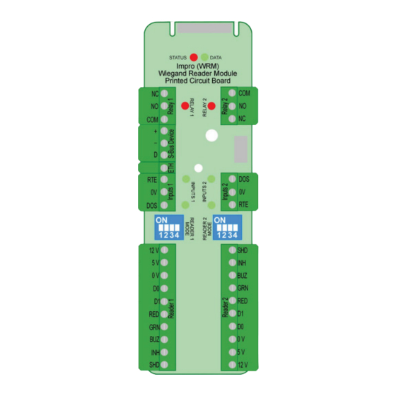
Page 11: Electrical Connections
ELECTRICAL CONNECTIONS Key Component Positions Figure 3: Impro WRM Key Component Positions HMW300-0-0-GB-00 October 2013 Page 11... - Page 12 Connecting Multi Discipline Readers Figure 4 shows a typical electrical connection diagram for the “clustered” Impro WRM. Figure 4: Typical Clustered Impro WRM Electrical Connections NOTE: * Refer to Figure 2 for Arc Suppression details. NOTE: The ideal cable distance between the Impro WRM and its Multi-discipline Reader MUST NOT exceed 150 m (164 yd).
- Page 13 Connecting to Wiegand Readers Figure 5: Connecting Impro WRM to Wiegand Reader NOTE: When connecting the Wiegand Keypad Mullion Reader (WKM900) or the Wiegand Junction Box Reader (WJB900), use the cable colours displayed in brackets. NOTE: Connection details remain the same for all Wiegand models. NOTE: Use the connections shown here, when connecting a Sagem MA100, MA200, MA300 or MA500 or Magstripe Reader to the Impro WRM.
- Page 14 Connecting to a Multi-mode Remote Figure 6: Impro WRM Connected to a Multi-mode Remote NOTE: Connection details remain the same for all Multi-mode Remote models. NOTE: The cable distance between the Impro WRM and its Multi-mode Remote MUST NOT exceed 10 m (33 ft). HMW300-0-0-GB-00 October 2013 Page 14...
- Page 15 Connecting other Devices Figure 7: Connecting other Devices to the WRM HMW300-0-0-GB-00 October 2013 Page 15...
- Page 16 S-Bus and Power Wiring for Remote Installation Figure 8 shows how to power the Impro WRM and its relay-driven loads in an “unclustered”, remote installation position. Figure 8: Typical S-Bus and Power Wiring for Remote Installation NOTE: The wiring of the RTE, DOS and Reader Terminals remains the same as shown on pages 12 to 14.
- Page 17 Power-on Self-test The Power-on Self-test tests the RAM and Flash Checksums. If any parameter in the Module Self-test fails, the connected Readers will emit a continuous beep for 2 seconds before the 2 short start-up beeps. When the Terminal passes the Self-test, any Readers attached will emits two short beeps, each 200 ms in duration, separated by a 200 ms inter-beep pause.
- Page 18 USER NOTES HMW300-0-0-GB-00 October 2013 Page 18...
- Page 19 USER NOTES HMW300-0-0-GB-00 October 2013 Page 19...
- Page 20 This manual is applicable to the Impro (WRM) Wiegand Reader Module, HMW700-0-0-GB-01, and HMW701-0-0-GB-00 (The last two digits of the Impro stock code indicate the issue status of the product.) Impro\Access Portal\WRM Wiegand Reader October HMW300-0-0-GB-00 Issue 01 Module\English Manuals\LATEST ISSUE\ 2013 conwrm-insm-en-01.docx HMW300-0-0-GB-00...
Need help?
Do you have a question about the HMW701-0-0-NN-XX and is the answer not in the manual?
Questions and answers