Table of Contents
Advertisement
02/11/2011
D
ATA PRIMA EMISSIONE
ELECTROMYOGRAPH
Redaction:
SALES – M. DELLACORNA
GM – A. DELLACORNA
Check:
GM – A. DELLACORNA
Approval:
GM – A. DELLACORNA
Data: 24/02/2012
Revision:
Revision:
01
This device complies with Part 15 of the FCC Rules. Operation is subject to the following two
conditions: (1) this device may not cause harmful interference, and (2) this device must accept
any interference received, including such that may cause undesired operations.
Any change or modification not expressly approved by Cometa Srl for compliance could void
WAVE PLUS - USER MANUAL
"WAVE PLUS"
MULTICHANNEL
USER MANUAL
Revision: 01
Approval Date:
24/02/2012
The system is classified according to 93/42/CEE regulation
the user's authority to operate the equipment.
Code: WPMENG
Changes Description:
Revision post IMQ review
C
. WPMEMG
OD
01
REV
Pag. 1 di 37
Advertisement
Table of Contents

Summary of Contents for COMETA WAVE PLUS
- Page 1 (1) this device may not cause harmful interference, and (2) this device must accept any interference received, including such that may cause undesired operations. Any change or modification not expressly approved by Cometa Srl for compliance could void the user’s authority to operate the equipment.
-
Page 2: Table Of Contents
LABELS ....................................32 : ......................................32 : ................................32 RIEF CASE WITH CHARGER ): ..................33 NDUCTIVE CHARGER INSIDE THE BRIEF CASE UP TO TWO UNITS : ......................................33 LETTRODI TECHNICAL SPECIFICATIONS (WAVE PLUS 16 CH) ....................35 ......................................37 UITABILITY... -
Page 3: Introduction
2. D ESTINATION AND CLASSIFICATION Wave Plus is a system for the data collection of biologic signals; the main system feature is the absence of cables between the transmitters on the patient and the data receiver/recording unit. This allows the acquisition of EMG and accelerometer signal while patient is free to move. - Page 4 Pag. 4 di 37 ATA PRIMA EMISSIONE Wave Plus system is classified according to CEI 60601-1:1998: - The applied part is a BF type according to CEI EN 60601-2-40 regulation (icon): - Second class device working with an external power supply providing power to internal peripheral units;...
-
Page 5: How To Use It
To use the Wave Plus system only as an inertial acquisition system, that is by using only the accelerometers included in the probes and not the EMG signal acquisition, it is sufficient to attach or strip the probes in the designated place, without any need for pre-gelled electrodes. -
Page 6: Wave Plus System Components
Pag. 6 di 37 ATA PRIMA EMISSIONE 3. W LUS SYSTEM COMPONENTS The following representation shows all Wave Plus components. The standard configuration of the system is composed of: EMG / accelerometer wireless modules, whit snap connections to the electrodes;... -
Page 7: Fundamental, Optional And Accessory Components
Accessory Foot-switch Electrodes Accessory 3.2 Wireless electrodes The Wave Plus system module is composed of two parts: The conditioning signal module, with active circuitry for signal radio-transmission; Power supply module and I/O interface including rechargeable battery, recharge coil, and the... - Page 8 . WPMEMG WAVE PLUS - USER MANUAL 02/11/2011 Pag. 8 di 37 ATA PRIMA EMISSIONE The power supply module is connected to the acquisition unit through a sliding mechanism; the unit disassembly should be done only during maintenance (exhausted battery or electric wire deteriorated).
-
Page 9: Base Unit
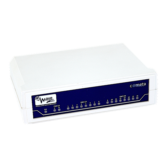
. WPMEMG WAVE PLUS - USER MANUAL 02/11/2011 Pag. 9 di 37 ATA PRIMA EMISSIONE 3.3 Base unit The base unit has a front panel with status LEDs. The signals are: LED off: the electrode is non active; LED on: green light: the electrode is active. -
Page 10: Docking Module
. WPMEMG WAVE PLUS - USER MANUAL 02/11/2011 Pag. 10 di 37 ATA PRIMA EMISSIONE The base unit has a RF transceiver at 2,4 GHz, a microprocessor for data synchronisation and separa- tion, D/A converter, a USB port to connect the host PC. -
Page 11: Wave Plus System Use
Linked to a PC through the USB port for visualisation, system control and digital data stor- age of EMG and basography (third party software not produced by Cometa srl). The two configurations can be used simultaneously. -
Page 12: Supported External Devices
EMG and basographic signals are available in continuous on analog output connector J26. 4.1.1 Supported external devices The Wave Plus system can be connected to analog devices commonly used in clinical and scientific en- vironments; these are the features required by systems: At least 8 or 16 EMG data collection channels, configured for signals with Zout = 100 ohm and an amplitude of ±... -
Page 13: Layout Of Cable Connections
. WPMEMG WAVE PLUS - USER MANUAL 02/11/2011 Pag. 13 di 37 ATA PRIMA EMISSIONE 4.1.2 Layout of cable connections Pin out of the analog output connector. Y 15 Y 15 Y 14 Y 14 Y 13 Y 13 GND_ANA... -
Page 14: Digital Mode
ATA PRIMA EMISSIONE 4.2 Digital mode To operate the system: Connect Wave Plus USB cable to the PC USB port. The power is taken directly from the USB port; The use of Personal Computer non-complying with IEC 60950 can cause electric shock and damage the system. -
Page 15: External Trigger
The operation of the system Wave Plus is now under the control of the Personal Computer. Refer to the User Manual supplied by the manufacturer of third party software for the description of the oper- ational commands. -
Page 16: Trig In
“Trig out” signal at “0” logic level when the system is not acquiring 4.2.1.3 Strobe IO The line "Strobe IO" is used for synchronization of a second Wave Plus receiver for the expansion to 32channelsof the system. This line is used by the system and should only be connected to another Wave... -
Page 17: How To Use The Trigger Port
TMS stimulation). In this latter case, we suggest to record both, the signals coming from the Wave Plus analog output and the trigger signal, using the same A/D converter. In that way, not only the Wave Plus data, but also the... -
Page 18: Supported External Devices
EMG signals from the Wave Plus analogue port, you should also consider the 13 ms delay related to the Wave Plus analogue output. In this case you should correct the recorded data in order to remove the 13 ms delay. NOTE THAT the 14 ms delay is constant and it can be easily removed by shifting the... -
Page 19: Led Signalling During Operation
Pag. 19 di 37 ATA PRIMA EMISSIONE The Personal Computer linked with the Wave Plus system has to comply with IEC 60950 regulation and has to be placed outside the patient’s area. The use of Personal Computer non-complying with IEC 60950 is allowed using a medical class insulation transformer to power the PC. -
Page 20: Electrodes Battery Recharge
Pag. 20 di 37 ATA PRIMA EMISSIONE Warning: the quality of the EMG signal acquired by the Wave Plus system is linked to the quality of the contact between electrode and skin; to obtain best results: 1. Use pre-gelled electrodes certified for a medical use and complying with the 93/42/CEE regulation;... -
Page 21: Led Indicator Of The Electrodes
How to use the device in an environment in which a wireless LAN is working If the Wave Plus receiving unit is close to an active WLAN unit, some interference could occur causing a loss of EMG data. Moving away the two units, the system would work properly, at least one or two meters. - Page 22 Wave Plus of at least 3 meters. How to use the device with disturbing electromagnetic fields If strong electromagnetic fields are in the environment where Wave Plus works, some interference could occur during the data transfer via USB, causing a loss of EMG data.
-
Page 23: Piezoresistive Sensors
. WPMEMG WAVE PLUS - USER MANUAL 02/11/2011 Pag. 23 di 37 ATA PRIMA EMISSIONE Ask the patient if he/she is sensitive to electrode gel and to polycarbonate of the external shell. Do not use in presence of devices essentials to life support. - Page 24 . WPMEMG WAVE PLUS - USER MANUAL 02/11/2011 Pag. 24 di 37 ATA PRIMA EMISSIONE Piezoresistive sensors for the gait cycles events detection are placed under the foot surface, in a position that allows a precise measurement of support and toe off. Up to four sensors for foot are available, and these are displaced in the typical positions: Toe sensor n.
-
Page 25: System Maintenance
. WPMEMG WAVE PLUS - USER MANUAL 02/11/2011 Pag. 25 di 37 ATA PRIMA EMISSIONE The FSW sensor plug isn’t polarised and can be connected in both ways; the FSW electrode socket has a white coloured label to make easier the numeric assignment of sensors. -
Page 26: Replacement Of Electrode Battery
02/11/2011 Pag. 26 di 37 ATA PRIMA EMISSIONE Wave Plus system does not contain parts repairable by the user with the exception of the batteries; for standard maintenance see the following chapters. 5.2 Replacement of electrode battery After about 300 charging/discharging cycles, the battery could reduce its electric capacity that leads to a shorter time of use of the electrodes. - Page 27 . WPMEMG WAVE PLUS - USER MANUAL 02/11/2011 Pag. 27 di 37 ATA PRIMA EMISSIONE 3. Extract the battery after gently prying it housing shown in the picture. 4. After having removed battery, pull the connection cable VERTICALLY in order to detach...
-
Page 28: Electrode Battery Characteristics
. WPMEMG WAVE PLUS - USER MANUAL 02/11/2011 Pag. 28 di 37 ATA PRIMA EMISSIONE Take battery and follow the same steps backwards install it inside the probe. 7. Carefully in- sert the new battery, mak- ing sure it is... -
Page 29: Warnings About Electrodes Battery
Use of non original batteries Change the exhaust batteries with original ones supplied by Cometa. Use of non original batteries could cause damage to the unit and safety risks for patient and operators; use of non original batteries will make the warranty void. -
Page 30: Warnings For Battery Disposal
5.4.3 Warnings for device disposal Base unit, electrodes and optional of the Wave Plus system have to be disposed off complying with national and local limitation for electronic devices and with Euro- pean Directive 2002/95/CE, 2002/96/CE, 2003/108/CE. -
Page 31: References
02/11/2011 Pag. 31 di 37 ATA PRIMA EMISSIONE To clean Wave Plus system components use a soft cloth damped with neutral soap. System components are NOT protected by liquid infiltration. The cleaning of the system elements has to be done: 1. -
Page 32: Labels
. WPMEMG WAVE PLUS - USER MANUAL 02/11/2011 Pag. 32 di 37 ATA PRIMA EMISSIONE 6. L ABELS 6.1 Base Unit: Label composition: REF.: REFERENCE NUMBER LOT.: PRODUCTION LOT IDENTIFIER S.N.: PRODUCT SERIAL NUMBER 6.2 Brief case with charger:... -
Page 33: Inductive Charger
The electrodes are made of two parts; the upper part is permanently pad printed with the brand “Wave Plus” on the top. The lowe part is permanently pad printed with the brand “Cometa” on one side and “Wave Plus” on the other side. - Page 34 Where the first field (from three to six characters) is the code of the item (for example, WPPSC: power supply of Wave Plus) and the last 4 elements is the year and the lot of production (for example, 1101 =...
-
Page 35: Technical Specifications (Wave Plus 16 Ch)
. WPMEMG WAVE PLUS - USER MANUAL 02/11/2011 Pag. 35 di 37 ATA PRIMA EMISSIONE 7. T ECHNICAL SPECIFICATIONS WAVE PLUS Base unit 2402 – 2480 MHz Transmission / Reception frequency Transmission power (ARP) 0,45 mW Number of channels (16 EMG + 48 ACC + 2 FSW) - Page 36 . WPMEMG WAVE PLUS - USER MANUAL 02/11/2011 Pag. 36 di 37 ATA PRIMA EMISSIONE Stand by time (100% charged battery) > 180 gg. EMG input +- 2.5 mV 10 Hz – 500 Hz (or 1 KHz) bandwidth 16 bit – 2 Ks/sec.
-
Page 37: Suitability
. WPMEMG WAVE PLUS - USER MANUAL 02/11/2011 Pag. 37 di 37 ATA PRIMA EMISSIONE Power supply cable 2,1x5,5 S 11,5 coax (+central) Additional specifications Input impedance: 20MOhm CMRR: >120dB (true differential electrodes without reference elec trode); SNR: >50dB; Hardware filtering (LP and HP):...
Need help?
Do you have a question about the WAVE PLUS and is the answer not in the manual?
Questions and answers