Table of Contents
Advertisement
Quick Links
P
A R T S
M
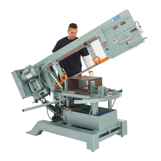
Mitre Band Saw
Installation and Operating Instructions
Note: Not all saw parts are shown in this booklet
Hydraulic Feed
Motor
Drive Wheel
End
Pulley Box
Speed
Reducer
Head Weight
Adjustment
Compensating
Spring Assembly
Cart Wheel
107 W. Railroad Street • P.O. Box 930219 • Verona, WI 53593-0219
Phone: (608) 845-6472 • Fax: (608) 845-5199 • www.ellissaw.com
1 - 8 0 0 - 3 8 3 - 5 5 4 7
C
A T A L O G
. C
F G
O M P A N Y
Replaceable Aluminum Saw Table
Moveable Guide Arm
Control
Bearing Carrier Assembly
2 H
, I
.
N C
Automatic Shut-Off Switch
Chip Tray
Idler Wheel End
T-Handle
Blade Tension
Adjustment
Idler Spindle
Adjusting Plate
Blade Guide
Assembly-Idler
Vise
Telescoping Handle
with Grip
Adjustable Legs
Advertisement
Table of Contents

Summary of Contents for Ellis 90H
- Page 1 A R T S A T A L O G O M P A N Y Mitre Band Saw Installation and Operating Instructions Note: Not all saw parts are shown in this booklet Replaceable Aluminum Saw Table Automatic Shut-Off Switch Idler Wheel End Moveable Guide Arm Hydraulic Feed...
-
Page 2: Blade Guide Assembly
L A D E U I D E Page 2 Complete Assembly Bearing Only Complete Assembly Blade Guide Assembly Part Number For Models 1600 1800 1000 1440 2000 Item No. 1100 1200 1500 3000 4000 Description Complete Assy. 9016DC 5370 5539 5720 5732... -
Page 3: F E E D C O N T R O L
6350 1800 6366 2000 6350 3000 6366 4000 6366 Chip Brush Assembly Part No. 5550 Ellis Mfg. Company, Inc. 107 W. Railroad Street • P.O. Box 930219 • Verona, WI 53593-0219 Phone: (608) 845-6472 • Fax: (608) 845-5199 • www.ellissaw.com... - Page 4 Page 4 Mitre Head Locking Handle ALL MODEL SAWS Item Part Description 4966 Mitre Head Locking Handle 4311 Flat Washer Bearing Carrier Assembly Press center button to reset ratchet in Handle Part Number For Models 1100 1800 1200 2000 Item 1500 3000 Description...
-
Page 5: Operation
& O N S T A L L A T I O N P E R A T I O N Page 5 CAUTION: Disconnect power supply cord from power source before changing the blade or making any other repair or adjustment to the saw. Installation Instructions 1. -
Page 6: Maintenance
& O N S T A L L A T I O N P E R A T I O N Page 6 Troubleshooting Crooked Cuts 1. Check blade for worn or broken teeth and replace if needed. new blade. As an example, a .033" feeler gauge would be used to set the guides for a .032"... -
Page 7: Air Cooling System
O O L I N G Page 7 Air Tube Between Solenoid And Air Nozzle Saw Blade Power Cord To Receptacle On Band Saw Connect To Shop Air Air Supply Tube Air Cooling System Part Number For Voltage Rating Item No. Description ENLARGEMENT OF AIR NOZZLE... - Page 8 6200 6240 Stock Support Second Roller Stand Assembly One Roller Micro-Adjustable Gauge Detail Stock Support Stand Part Number For Models 90H 1200 2000 900 1500 3000 1000 1600 Description/Item 4000 1100 1800 See Heavy Duty Stock Support Stand Single Stock Stand...
Need help?
Do you have a question about the 90H and is the answer not in the manual?
Questions and answers