Table of Contents
Advertisement
Advertisement
Chapters
Table of Contents

Summary of Contents for Seeing Machines Guardian Gen 2
- Page 1 FIELD SUPPORT MANUAL Guardian - Generation 2 (Gen2)
- Page 2 Guardian - Generation 2 (Gen 2). Please refer to the Guardian Field Installation Manual (June 2016) for installations of the previous generation of Guardian. All Guardian Gen 2 installations must be completed in accordance with this manual. This document is the standard for Guardian Gen 2 installations.
- Page 3 SECTIONS SECTION TITLE Preface Introduction to Guardian Gen 2 Installation of Guardian Gen 2 Service & Maintenance of Guardian Gen 2...
- Page 4 REFERENCE DOCUMENTS The below referenced documents can be downloaded from the Technical Communication Portal (TCP) at tcp.seeingmachines.com if you require access to the TCP, please make a request via the ‘Apply Here’ button on the TCP website. ITEM TITLE Knowledgebase Installation Checklist Tutorial videos Technical Support Bulletins...
- Page 5 FCC Part 15 Digital Emissions Compliance We, Seeing Machines, Level 1, 11 Lonsdale St, Braddon, ACT, 2612, Australia, +61 2 6103 4700, declare under our sole responsibility that the product Guardian complies with Part 15 of the FCC Rules.
- Page 6 End-users and installers must be provided with antenna installation instructions and transmitter operating conditions for satisfying RF exposure compliance. FCC RF Radiation Exposure Statement: This equipment complies with FCC radiation exposure limits set forth for an uncontrolled environment. This equipment should be installed and operated with minimum distance 20cm between the radiator &...
- Page 7 FIELD SUPPORT MANUAL Section 1 – Introduction to Guardian Gen 2-2...
-
Page 8: Table Of Contents
Table of Contents OVERVIEW ............................. 3 ABBREVIATIONS .......................... 4 TERMS ............................7 SAFETY ............................9 PACKAGING ..........................10 STANDARD COMPONENTS ..................... 11 OPTIONAL COMPONENTS ....................... 19 INSTALLATION TOOL KIT (Provided by Trainer) ..............20 REQUIRED TOOLS FOR INSTALLATION ................. 21 ROLES AND RESPONSIBILITIES ................... -
Page 9: Overview
1. OVERVIEW The aim of this section is to introduce the acronyms, components anof Guardian Gen 2 Section 1 A certified Guardian Technician must read and understand this section before commencing a physical installation of the System. -
Page 10: Abbreviations
2. ABBREVIATIONS ABBREVIATION MEANING Access Point Name-Relates to SIM Card Cellular CELL -Wireless communications via a communications network Direct Current Demo Demonstration DSSi Driver Safety System interface Electromagnetic Compatibility Forward Facing Camera Field Of View Global Positioning System Health, Safety and the Environment In Cab Sensor (also known as the Driver Facing Camera) Ingress Protection Marking (for use with connectors) Internet Protocol (for use with computers) - Page 11 -Refers to a webpage link Secure Digital -Refers to the SD memory card Subscriber Identity Module -As in SIM Card for a communications device Seeing Machines Technical Communications Portal Universal Serial Bus High-Definition Multimedia Interface HDMI -Refers to video output...
- Page 12 MEASUREMENTS MEANING Ampere Celsius Centimeter Direct Current Feet gram Gigabyte Fahrenheit Inch Kilogram Pound Meter Millimeter Nanometer Ounce Revolutions per minute Volt...
-
Page 13: Terms
3. TERMS TERM DEFINITION Guardian Gen 2-2 has an inbuilt function to record all footage for a set period Black Box of time. This is known as the Black Box Recorder which is similar to a Flight Information Recorder - “Black Box”. - Page 14 Soft Install See ‘Non-Standard Install’ Refers to the Guardian Gen 2-2 System but predominately relates to the System hardware. The angle in degrees, the In-Cab Driver Facing Sensor is mounted left or right in relation to the driver’s head. Value range between -20 to 20 degrees.
-
Page 15: Safety
4. SAFETY Safety must be considered prior to installing Guardian. You must comply with the client’s site safety policies, processes, arrangements and requirements in place at the site where you will install or maintain the System. If such policies do not exist it is a requirement to follow the SAFE WORK practices detailed below. -
Page 16: Packaging
5. PACKAGING ITEM DESCRIPTION IMAGE Packaging: Brown Carton Size: 280x270x560mm Weight: 4.7kg Markings: Inner Contents: 2 layers of shaped Cartons cardboard protecting components Documentation: Installation Paperwork Checklist... -
Page 17: Standard Components
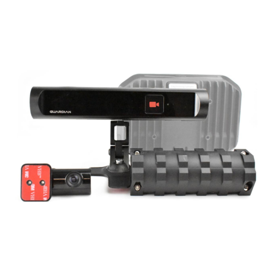
6. STANDARD COMPONENTS ITEM QTY DESCRIPTION IMAGE Controller Unit Hardware: Input voltage: 10 to 30V DC Size: 182x124x43mm Function: This is the Processor of the system which runs the entire system Connection: Size: Adjustment: Function: Controller Mounting Pan: Comes in 2 parts Connection: Size: 218x146x54mm (Controller inside) Adjustment:... - Page 18 Adjustment: Function: M6 OD 11.8 SS Split Washer: Connection: Size: Adjustment: Function: Fastener M6 OD 20 SS Flat Washer: Connection: Size: Adjustment: Function: ICS Module Hardware: Connection: To the ICS Cable Sensor viewing angle: ??? Function: This is the In-Cab Sensor, Audio and IR Illumination of the system that alerts and detects fatigue and distraction for the driver Size: ??x??x??mm...
- Page 19 Mounting Arm Assembly: Connection: Size: Adjustment: Function: Screw in dash mount Connection: Size: Adjustment: Function: Fastener 10 Gauge x 25mm black self- tapping screw CSK Used with Screw in dash mount Connection: Size: Adjustment: Function: Adhesive dash mount Connection: Size: Adjustment: Function: Alcohol wipe...
- Page 20 Function: Primer pen for VHB tape For adhesive dash mount (warning could damage dashboard on removal of this mount) Connection: Size: Adjustment: Function: FFC Hardware: Connection: To the Controller Unit Cable: 7m long cable Adjustment: 1.5mm Allen key for pitch control (supplied by installer) Size: 72 x 41 x 40 mm Field of View: H105.5°xV63.4°...
- Page 21 MFC Hardware: Connection: To the Controller Unit Cable Length: 1m Function: Provides connection for CCDC, Micro USB OTG, Vibration Motor, and other FMS integration Connection: Size: Adjustment: Function: Hose Clamp Hardware: Connection: To the Vibration Motor / Mounting Plate Size: 150mm Hex Head 8mm Function: To clamp the vibration motor to the driver’s seat without the use of screws Connection:...
- Page 22 Fastener – Tek Screw: Connection: Size: 30x8mm Hex Head 8mm Function: to be used with the Vibration Plate Hardware Connection: Size: Adjustment: Function: 3G Antenna Hardware: Connection: To the Controller Unit Cable Length: 4m Size: ????? Function: To provide the Controller unit ample 3G communication Connection: Size:...
- Page 23 Double sided tape VHB 20x33mm Connection: Size: Adjustment: Function: Power Cable Hardware: Connection: To the Controller Unit Cable Length: 5m Function: 3 core cable to provide battery, ignition and ground to the Controller Unit Connection: Size: Adjustment: Function: In-line Fuse Holder: Connection: To the open-ended side of the Power Cable to be used with Crimps and Joiners on the Battery and Ignition wires as...
- Page 24 Adjustment: Function: Blue Wire Joiner Connection: Size: Adjustment: Function: Blue Crimp Terminal Ring 4mm Connection: Size: Adjustment: Function: Blue Crimp Terminal Ring 6.3mm Connection: Size: Adjustment: Function: Blue Crimp Terminal Ring 10mm Connection: Size: Adjustment: Function: Zip Ties 4.8mm Connection: Size: Adjustment: Function:...
-
Page 25: Optional Components
25mm hole size Blanking grommet Connection: Size: Adjustment: Function: 7. OPTIONAL COMPONENTS Optional Extra’s Please see the TCP for instructions on additional hardware... -
Page 26: Installation Tool Kit (Provided By Trainer)
8. INSTALLATION TOOL KIT (Provided by Trainer) TOOL IMAGE Security Torx 20 (T20) Key 24/7 Support Business Card USB Recovery Dongle Information Card USB Recovery Dongle (minimum size 4GB) USB to Ethernet Adapter Ethernet Cable... -
Page 27: Required Tools For Installation
9. REQUIRED TOOLS FOR INSTALLATION TOOL IMAGE 1.5mm Allen Key To adjust locking screw on the FFC Installation and Maintenance functions Laptop / Smart (Windows7, Windows8, Windows10 or Phone or Tablet Apple are preferred) Laptop must have an ethernet port or a Protractor / Smart Determining camera Pitch and Yaw Phone app... - Page 28 Ratchet spanner set 8, 9, 10, 11, 12, 13, 14, 15, 16, 17, 18, 19mm Vice grips Drill bits 2, 4, 6, 7mm Hole Saws 25mm (1in) Multi-meter and leads Wire cutters Wire strippers...
- Page 29 Automotive crimpers Torch / Head Torch Scissors Utility Knife (Confirm site requirements) Cordless Drill Cordless Impact Driver Brush Electrical Tape...
-
Page 30: Roles And Responsibilities
20 or more successful installations with no breach of quality or safety and has Supervises FSA completed the Seeing Machines “Train the Can train FSA Trainer” Course. This position is authorised to conduct On the Job Training (OJT) for Course 1... - Page 31 Aids in connecting systems A highly experienced Seeing Machines Provides troubleshooting to employee to aid installers in connecting technicians systems and troubleshooting in the field Provides customer support...
- Page 33 OVERVIEW ............................4 LAPTOP & SMART PHONE SETUP ....................5 SECTION 2 OVERVIEW ......................5 WINDOWS SETUP ........................5 MAC SETUP ..........................8 CHROME SETUP ........................8 SMART PHONE SETUP ......................12 2.5.1 PHOTO ARCHIVE ......................12 2.5.2 ANDROID ........................15 2.5.3 IPHONE ..........................
- Page 34 SECTION 6 OVERVIEW ......................49 24/7 SUPPORT DETAILS ......................49 ACTIVATING A VEHICLE ......................49 OTHER DUTIES WITH 24/7 SUPPORT ..................49 6.4.1 TROUBLESHOOTING ...................... 49 6.4.2 VEHICLE SWAP ......................50 6.4.3 BLACKBOX RECOVERY ....................50 6.4.4 CONFIGURATION CHANGE ON A VEHICLE ..............50 FINAL QA ............................
-
Page 36: Laptop & Smart Phone Setup
2.1 PART 2 OVERVIEW This section is on how to configure your equipment for use in the field 2.2 WINDOWS SETUP Windows Setup (Supports Vista,7,8,10) If your laptop runs Windows, these instructions will setup your laptop to communicate with the Controller Unit through the Ethernet Port (if you do not have an Ethernet port you may be required to obtain a USB to Ethernet Adapter) Notes:... - Page 37 Right click on “Ethernet” this can also be called “Local Area Connection”. And click on “Properties” 1. Scroll down to “Internet Protocol Version 4” and click on it to select it 2. Then click on “Properties”...
- Page 38 1. Select “Use the following IP address:” 2. In the IP address: field type 192.168.1.2 3. Click into the subnet mask and it will auto populate to 255.255.255.0 4. Then click “OK” to save these settings Note: When the connection is made between the Laptop and Guardian Controller Unit, the Ethernet section will show “Network [#]”...
-
Page 39: Mac Setup
2.3 MAC OS SETUP MAC OS (X) (Supports OS X) These instructions will setup your Apple Mac laptop to communicate with the Controller Unit through the Ethernet Port (if you do not have an Ethernet port you may be required to obtain a USB to Ethernet Adapter) Notes: If you have an IT Administrator you may not have access to these settings, if so you may need IT... - Page 40 Search or find “Network” and double click om it 1. Select “Ethernet” in the left-hand pane 2. Click in the dropdown And select and click “Manually” to configure the ethernet settings...
- Page 41 1. Enter under “IP Address:” 192.168.1.2 2. Click into the subnet mask and it will auto populate to 255.255.255.0 3. Click “Apply” to save the settings Note: When the connection is made between the Laptop and Guardian Processor Unit, the Ethernet section will show Connected To connect to the Guardian Controller, we recommend using Google Chrome setup on your laptop, see below for further details...
-
Page 42: Chrome Setup
2.4 CHROME SETUP Google Chrome is recommended as the browser of choice to use for setting up the system from its factory default setting to become a customized system for a company’s fleet Google Chrome Setup If you do not have Google Chrome on your laptop you can download the latest version at; www.google.com/chrome and follow the prompts If you already have Google Chrome, it is... -
Page 43: Smart Phone Setup
Seeing Machines will ask to recall the photos off the installer if an issue develops after the install, this may happen weeks after installation and your collected photos will act as evidence of correct... - Page 44 An opening setup screen will appear 1. Make sure “Backup & Sync” is on 2. Make sure “(free unlimited storage)” is selected 3. Make sure your Gmail/Google Account is entered, then click “Done”...
- Page 45 To access Google Photos you can use the app as normal. Or alternatively you can go to www.google.com 1. Sign into your Gmail/Google Account 2. Click on the 9 dots to reveal your app drawer 3. Click on the “Photos” icon to display all your pictures If you cannot see the “Photos”...
-
Page 46: Android
2.5.2 ANDROID TO REPLACE LAPTOP This is a future Seeing Machines development --- Coming Soon 2.5.3 IPHONE TO REPLACE LAPTOP This is a future Seeing Machines development --- Coming Soon... -
Page 47: Technical Communications Portal (Tcp) Information
2.6 TECHNICAL COMMUNICATIONS PORTAL (TCP) INFORMATION The TCP is not only an area for your online training, it also supplies you with a wide range of resources such as: • Datasheets • User Manuals • Installation Updates • Knowledgebase • Error codes •... - Page 48 To perform a factory reset use a pen or something similar to push and hold the button for 10 seconds, the green LED to the right will flash when the unit has been reset 2.7.2 USB RECOVERY DONGLE RESTORATION The TCP has the latest software download for the guardian system, your Recovery USB Dongle will NOT be programmed when you receive it in your installer kit given to you in your training.
- Page 49 Unscrew the Mounting Pan’s 2 screws to release the Controller Unit using your T20 Driver Take out the Controller Unit and unscrew the 2 Cover Plate screws, using your T20 Driver Slide the Cover Plate down to access the Maintenance Panel Insert the USB Recovery Dongle into the USB port on the Maintenance Panel...
- Page 50 Turn on the vehicle Observe the LED light on the Controller Unit. When the recovery has finished the light will ?????? The recovery process is now complete, remove the USB Recovery Dongle. The system will reboot automatically. Refer to the IVS Installation Wizard to setup and configure the system...
-
Page 51: Preparation For Installation
Setup of Software Store Photos • Make sure all site safety rules are followed • Using your Recovery Dongle update the • Archive photos for Seeing Machines to recall before starting on the vehicle. system to the latest version. if needed. -
Page 52: Product Installation
4.1 PART 4 OVERVIEW These installation instructions allow you to successfully install the Guardian Generation 2 – 2 Box Solution. Below describes the function and mounting specifics of each piece. -
Page 53: Component Interconnections
4.2 COMPONENT INTERCONNECTIONS • • • •... -
Page 54: Installation Records
You can find a more detailed explanation of how to fill in the checklist at: tcp.seeingmachines.com/forms The checklist contains all 24/7 support details for the System Registration It also contains the weblink for the Technical Communications Portal (TCP) where you’ll find this manual and any other information including the Seeing Machines knowledgebase... - Page 55 Locating the serial numbers: The serial number is located under the Controller Panel on the Gen2-2 Controller You must have your T20 driver to access this panel Unscrew the two bolts of the Controller Panel Slide the connector panel downwards to reveal the Product number and Serial number Record the...
-
Page 56: Component Installation Specifics
4.4 COMPONENT INSTALLATION SPECIFICS 4.4.1 SIM CARD INSTALLATION SIM Card Installation Important Points to Note: Activated SIM cards are to be provided by the customer. The SIM card size requirement is a Nano SIM. Confirm with the customer that the SIM has been activated with the telecommunications provider Mounting Location: The SIM card is inserted in the Guardian... - Page 57 The Nano SIM is inserted so that the metal chip is visable. Match the cut corner on the SIM to the matching corner on the tray, and push the tray closed...
-
Page 58: Controller Installation
4.4.2 CONTROLLER UNIT INSTALLATION Controller Unit Image When installing the Contoller Unit you will need; The Contoller Unit The Mounting Pan Should have at least 4 screws Should be orientated to easily access the 2 bottom T20 bolts And Fasteners Each piece should be used to securely mount the unit so that it is vibration proof... - Page 59 A good place is also where you have considered the length of the provided cables Types of Mounting: The mounting pan is a light weight mounting template, choose 3 to 4 of the 6 mounting holes to suit your mounting location The orientation of the Mounting Pan should be aligned so that you have easy...
- Page 60 4.4.3 IN-CAB SENSOR MODULE INSTALLATION In-Cab Sensor Module (ICS) Image Mounting Location: The In-Cab Sensor is to be mounted on the dashboard within -20 to 20 degrees of the driver’s straight ahead position, as shown in the image The ICS must be mounted so that there are no obstructions between the driver’s eyes at the ICS hardware Make sure ICS is in complete view of the...
- Page 61 Soft Mount: Soft Mount uses strong automotive grade double sided tape for adhesion (The Hard Mount is recommended by Seeing Machines. The Soft Mount method should only be used if the customer requests it) Make sure the vehicles surface has been cleaned;...
-
Page 62: Ffc Installation
Adjusting the Mounts: The Sensors mounting has 4 points of movement to allow the installer to change angles for optimum sensor placement, and ease of maintenance In your installer kit your T20 security Torx key can adjust these movements The ICS must be placed as level as possible in the horizontal position Make sure after adjustment the 4 locking bolts have been tightened to ensure a... - Page 63 Mounting Location:** The FFC is to be mounted so that the wipers clean the vision for the camera to It is to be mounted in the center of the windscreen so that it does not interfere with the drivers vision The FFC “Guardian”...
-
Page 64: Antenna Installation
Bonnet - Adjust the camera so that; The top of the image sees the • horizon The bottom of the image sees the • top of the bonnet No Bonnet - Adjust the camera so that; The top of the image sees the •... -
Page 65: Gps Antenna Installation
Types of Mounting: Tape Adjusting the Mounts: Distance between 3G and GPS TBD Distance to 3 party antennas TBD Distance to the controller TBD Important Points to Note: 4.4.6 GPS ANTENNA INSTALLATION GPS Antenna Mounting Location: The GPS antenna is to be mounted so that there is a clear line of sight to the sky The GPS antenna can see through;... -
Page 66: Vibration Motor Installation
4.4.7 VIBRATION MOTOR INSTALLATION Vibration Motor Mounting Location: The Vibration Motor is to be mounted on the driver’s seat. It should be located above the adjustment rails and within the red dotted lines The preferred method of mounting is clamping not drilling Note: It is not recommended to mount under the rails because the vibration cannot be easily felt by the driver... - Page 67 To avoid the cable breaking during normal vehicle operation, the seat must be able to move freely in all directions. The cabling must be installed with sufficient slack to allow this movement to occur. If the seat already has cabling, it is recommended that you follow that routing.
- Page 68 Bar Mount: Looking at the end of the vibration motor there is a ‘V’ shape edge and a flat edge, these can mount to different shapes The hose clamps are used to mount to any type of strong bar on the seat. 2 hose clamps are to be used, in any 2 of the 5 slots on the vibration motor.
- Page 69 When the screw mount has been screwed into position the vibration motor will mount to the screw mount Rotate the vibration motor so that the bar mount position sits on the screw mount Then use the hose clamps on the two outer slots to secure the vibration motor Adjusting the Mounts: Using an 8mm socket and your impact...
-
Page 70: Power Cable Installation
When the vibration motor is tightened, Zip tie down any excess hose clamp Important Points to Note: Make sure the hose clamps fall into the slots when tightening so the motor cant slide out Make sure the hose clamps are tight so the motor cant move around or slide The Vibration motor cables plug connects to the MFC cable, not straight to the... - Page 71 Mounting Location: Starting at the Controller, route the power cable back to the fuse box for power pickup, via a point that can be used as a tether for the Controller if it somehow becomes loose The tethering point must be close to the Controller.
- Page 72 At the fuse box Fuse holders are to be attached in line with the power connection on the battery and ignition wires Various ring terminals can be used depending on the connection type. For further information on crimping techniques refer to the “Installer Resources”...
-
Page 73: Mfc Installtion
Test battery and ignition connection to make sure they are the correct way around (the system still functions, but not correctly) Ensure the ground connection is a good connection, free of grease, paint, plastic, corrosion Secure the power cable to act as a tether, on a main unit, zip tie to structural part of the dash or under a screw 4.4.9 MFC INSTALLTION Multi-Function Cable (MFC) -
Page 74: Cabling Installation
The four pin connector plugs into Third Party Fleet Management Systems (FMS) Products (Optional extra) The female micro USB connector plugs into Third Party FMS Products (Optional extra) The three pin connector plugs into the Cruise Control Disable Cable (CCDC) (Optional extra) Adjusting the Mounts: Zip tie the MFC cable to existing cable... - Page 75 Placement of cables: After all system components have been installed and their respective cable routed. The cables coming into the controller are to pass through the mounting arms cable slot. This keeps the cables neat and easy to zip tie together for cable management Cable relief: After all cables have been plugged into the Controller at the end of the installation,...
-
Page 76: Optional Extra's
4.4.11 OPTIONAL EXTRA’S Optional Extra’s Please see the TCP for instructions on additional hardware... -
Page 77: Summary Of Installation Process
4.5 SUMMARY OF INSTALLATION PROCESS • • • • • • • • • •... -
Page 78: Software Setup, Testing & Activation
5.1 PART 5 OVERVIEW 5.2 APPLYING LATEST SOFTWARE TO THE CONTROLLER Applying the Software The controller by default does not have software applied. Your Recovery USB Dongle is used to update the guardian system to the latest software version See Section 2.7 of this document to make sure you are up to date After the systems hardware has been installed the latest software will need to be applied You will need to do this with the Recovery USB... -
Page 79: Installation Wizard
Plug in the Recovery USB Dongle Plug in the power connector and wait until NOT SURE WHAT HAPPENS YET 5.3 INSTALLATION WIZARD Installation Wizard The Installation Wizard will always start after you have used your Recovery USB Dongle or performed a Factory Reset Make sure you have your Laptop setup to communicate to the Controller unit See Section 2 of this document for more information... -
Page 80: Calling Support For Activation
After the software has been setup for the installation, system checks need to be done to ensure the system is running optimally 6.1 PART 6 OVERVIEW 6.2 24/7 SUPPORT DETAILS 24/7 Support Center System Registration | Configuration | Troubleshooting support@seeingmachines.com AUS Tel: +61 2 6108 4313 USA Tel: +1 855 377 4636 Technical Communications Portal... - Page 81 6.4.4 CONFIGURATION CHANGE ON A VEHICLE The company authority can only make changes to the configuration change on the vehicle, this can be agreed through the companies Seeing Machines account manager 24/7 Support can aid in communication and apply changes through such authorities...
- Page 82 Final QA At the end of the installation a final quality assurance check is required Cables are cable tied and do not interfere with the function of the vehicle Cables are hidden from view as much as possible No rubbish is left in the vehicle from the installation All your tools have been removed All vehicle pieces and bolts are placed back on...
- Page 84 Table of Contents ............................. 3 ..........................4 ......................... 6 ........................9 .................... 10 ..................11 ......................12...
- Page 86 2.1. PREVENTATIVE MAINTENANCE...
- Page 88 3.1. Self Checks during boot-up • • • • • • • •...
- Page 89 • • • • • 3.2. System Test Mode • • • • • • • • •...
- Page 90 • •...
- Page 94 7.1. Blackbox Overview • • • •...
- Page 95 7.2. Copying Blackbox Data from the unit...
- Page 100 7.3. Delivering Blackbox Data to 24/7 Support • • • • • •...
Need help?
Do you have a question about the Guardian Gen 2 and is the answer not in the manual?
Questions and answers
Quero saber su valor comercial