Table of Contents
Advertisement
Quick Links
Advertisement
Table of Contents

Subscribe to Our Youtube Channel
Related Manuals for ORBCOMM CT 3000

Summary of Contents for ORBCOMM CT 3000
- Page 1 CT 3000/CT 3100 Installation Guide W000-C, Version 0.04 Mar 2018...
-
Page 2: Legal Notice
ORBCOMM, Inc. 395 W Passaic Street, Suite 325, Rochelle Park, NJ 07662 USA Phone 703-433-6325. The information in this document is for information purposes only and contains technical information and descriptions of the ORBCOMM product(s) and is subject to change without notice. -
Page 3: Contact Information
CT 3000/CT 3100 - INSTALLATION GUIDE CONTACT INFORMATION Visit ORBCOMM Online www.ORBCOMM.com Contact Customer Care Customer.Care@orbcomm.com (International) +1-703-433-6300 (North America) 1.800.ORBCOMM (1-800-672-2666) Headquarters 395 W Passaic Street, Suite 325 Rochelle Park, NJ 07662 USA Tel: +1-703-433-6300 Fax: 1-703-433-6400 Email: sales@orbcomm.com AS001, 0.01... -
Page 4: Table Of Contents
CT 3000/CT 3100 - INSTALLATION GUIDE TABLE OF CONTENTS Legal Notice ..........................2 Contact Information ........................3 TABLE OF CONTENTS ........................4 Preface ............................5 Purpose ..........................5 Notation ..........................5 Installation Procedure .....................6 RTU LEDs ........................9 2.1. Normal Mode ......................9 Regulatory Statements ....................10 AS001, 0.01... -
Page 5: Preface
CT 3000/CT 3100 - INSTALLATION GUIDE PREFACE Purpose This document describes the installation and operation process for ORBCOMM’s CT 3000 (p/n XT6475A31100030G) and CT 3100 (p/nXT6475A31100070G) GPS/cellular reefer tracking devices. Notation Images shown in this document may not be exactly as shown. -
Page 6: Installation Procedure
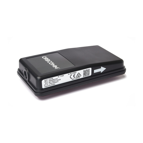
CT 3000/CT 3100 - INSTALLATION GUIDE INSTALLATION PROCEDURE 1. Gather the required tools. 2. Identify the system components. Figure 1: CT 3000/CT 3100 Device Figure 2: CT 3000/CT 3100 Harness 3. Disconnect the reefer power. 4. Determine the mounting location on the panel. - Page 7 CT 3000/CT 3100 - INSTALLATION GUIDE 5. Drill a 1-1/8” hole in the panel. 6. Feed the connector through from the back of the panel and connect to the device. 7. Remove the red backing tape and adhere the device to the panel so the arrow faces up.
- Page 8 CT 3000/CT 3100 - INSTALLATION GUIDE 8. Route the harness into the control box and connect to the 3-pin power and 7-pin serial connector. 9. Close the controller door and power up the reefer 10. Check the status of the reefer LEDs for correct operation.
-
Page 9: Rtu Leds
CT 3000/CT 3100 - INSTALLATION GUIDE RTU LEDS • Green LED: Next to push button. Used for GPS status • Tricolor LED (Red, Green, Blue): On center. Used for installation status and result when device is in installation mode. In normal mode, the Tricolor LED indicate status of Reefer Controller, Zigbee and Battery status. Each color of the LED will blink so that only one color will be ON at a time. -
Page 10: Regulatory Statements
CT 3000/CT 3100 - INSTALLATION GUIDE REGULATORY STATEMENTS FCC: This device complies with Part 15 of the FCC Rules. Operation is subject to the following two conditions: this device may not cause harmful interference, and this device must accept any interference received, including interference that may cause undesired operation. - Page 11 CT 3000/CT 3100 - INSTALLATION GUIDE Cet émetteur radio (identifier le périphérique par numéro de certification, ou le numéro de modèle si Catégorie II) a été approuvé par Industrie Canada pour fonctionner avec les types d'antennes énumérées ci-dessous avec le gain maximal admissible et l'impédance d'antenne requise pour chaque antenne type indiqué.
Need help?
Do you have a question about the CT 3000 and is the answer not in the manual?
Questions and answers