Advertisement
Quick Links
INSTRUCTIONS
ELITE FUSE FINDER KIT
MARTINDALE
Trusted by professionals
CONTENTS
1.
Introduction
1.1
Description
1.2
Unpacking and Inspection
1.3
Battery Installation
2.
Technical Specification
2.1
Transmitter
2.2
Receiver
3.
Operation
3.1
Precautions
3.2
Description of Functions and Indicators
3.3
Using the FD650/R and FD500/T or FD600/T as a
Fuse Finder
3.3.1
Pre-Check of the FD650/R and FD500/T or FD600/T
3.3.2
Locating a Fuse or Circuit Breaker
3.3.3
Using in Manual Threshold Mode
3.3.4
Using in Automatic Threshold Mode
3.3.5
Connecting the FD600/T using TL83 & TL88 Leads
3.4
Using the FD650/R as a Voltage Detector
3.4.1
Pre-Check of the FD650/R
3.4.2
Locating Live Wiring/Cabling
4.
Maintenance
4.1
Battery Replacement
4.2
Cleaning
4.3
Repair & Service
4.4
Storage Conditions
4.5
Warranty
N.B. The unit defaults to Manual Mode when switched on (see
sections 3.3.3 and 3.3.4).
E L E C T R I C
SAFETY INFORMATION: Always read before proceeding.
These instructions contain both information and warnings that are
necessary for the safe operation and maintenance of the FD650/R and
FD500/T or FD600/T. It is recommended that you read the instructions
carefully and ensure that the contents are fully understood. Failure to
understand the instructions and to comply with the warnings and
instructions contained herein can result in serious injury, damage or
even death.
In order to avoid the danger of electrical shock, it is important that
proper safety measures are taken when working with voltages
exceeding 30 V AC rms, 42 V AC peak or 60 V DC.
The FD650/R and FD500/T FD600/T must only be used under the
conditions and for the purposes for which they have been
constructed. Particular attention should be paid to the safety
instructions, the technical specifications and the use of the FD650/R
and FD500/T or FD600/T in dry surroundings.
Always check the FD650/R and FD500/T or FD600/T are in good
working order before use and that there are no signs of damage to
any unit. Do not use if damaged.
Keep these instructions for future reference. Updated instructions
and product information are available on our website:
www.martindale-electric.co.uk
Symbols
2
1.1 Description
The FD650/R is a combined AC voltage detector and fuse finder receiver
(when used in combination with the FD500/T or FD600/T transmitter).
As a fuse finder the FD650/R can be operated with either manual or
automatic setting of its sensitivity threshold to find the fuse or circuit
breaker that produces the maximum signal.
In manual mode the press of a push-button will set the sensitivity threshold
to bring the detected signal to mid scale on the bar graph.
In automatic mode the FD650/R will automatically set the sensitivity
threshold every time a signal of a greater magnitude is detected, to bring it
onto the bar graph scale.
In either mode the buzzer will continue to sound when a signal is present,
even when the signal is too small to be shown on the bar graph due to the
sensitivity setting.
When in the voltage detector mode the FD650/R employs the bar graph to
show the detected signal, and at the same time activates the buzzer. The
voltage detector function also has a built in test signal to check the
operation of its circuitry.
Other features of the FD650/R are Auto Power-down and Low Battery
Indication.
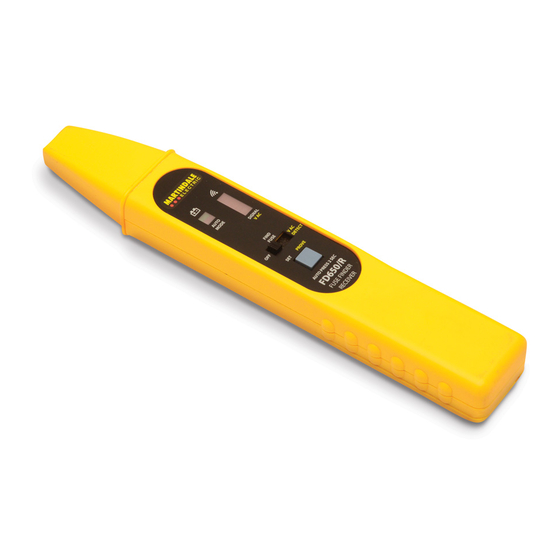
A three-position switch sets the FD650/R from OFF to either the Fuse
Finder or the Voltage Detector functions. A single push-button switch
controls all other operations of the FD650/R.
3
4
WARNING
AC (alternating current)
Earth ground
Safety information (refer to the manual)
Equipment complies with relevant EU directives
1. INTRODUCTION
Advertisement

Related Manuals for MARTINDALE FD650/R


Summary of Contents for MARTINDALE FD650/R
- Page 1 Unpacking and Inspection (when used in combination with the FD500/T or FD600/T transmitter). Battery Installation As a fuse finder the FD650/R can be operated with either manual or Technical Specification automatic setting of its sensitivity threshold to find the fuse or circuit Transmitter breaker that produces the maximum signal.
- Page 2 OFF to FIND (Fuse Finder) or VAC (Voltage indicator). Warning Hold the FD650/R by the bottom of the unit. Do not allow your fingers to go beyond the LED indicators. 1.1. LED’s:- There are two status LED’s on the LHS of the unit. The top one is green and shows battery status.
- Page 3 Hold the FD650/R against the first fuse or circuit breaker of the box as Figure 4. Correct shown in figure 4. The orientation of the FD650/R in relation to the fuse / The receiver must be held breaker must be as shown in figure 4 and it should be held in the centre of in this orientation in relation the fuse or circuit breaker.
- Page 4 Hold the FD650/R against the first fuse or circuit breaker of the box as shown in figure 4. The orientation of the FD650/R in relation to the fuse / breaker must be as shown in figure 4 and it should be held in the centre of the fuse or circuit breaker.