Advertisement
Quick Links
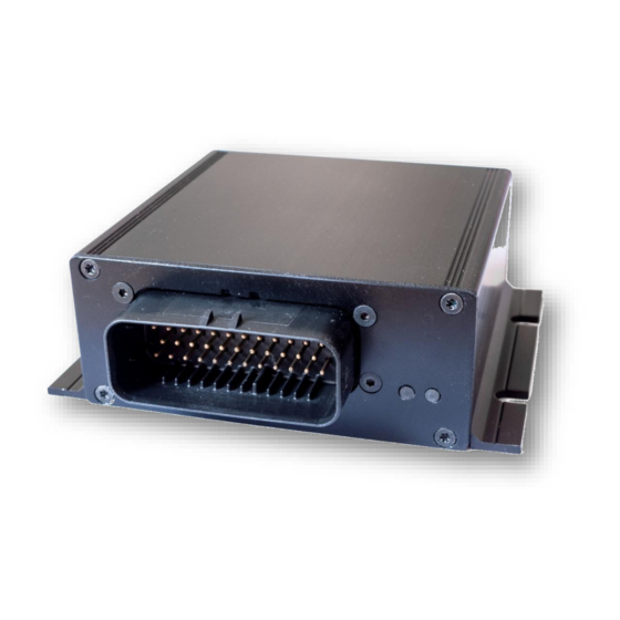
VICTRON CCGX-SUPPORTED ACTIVE BATTERY
MANAGEMENT SYSTEM REC ACTIVE BMS
Features:
robust and small design
-
4 cells
-
single cell voltage measurement (0.1 – 5.0 V, resolution 1 mV)
-
single cell - under/over voltage protection
-
single cell internal resistance measurement
-
SOC and SOH calculation
-
over temperature protection
-
under temperature charging protection
-
active cell balancing up to 2.5 A DC per cell
-
shunt current measurement (resolution 19.5 mA @ ± 500 A)
-
galvanically isolated user defined multi-purpose digital output
-
programmable relay (normally open or normally closed)
-
galvanically isolated RS-485 communication protocol
-
CAN communication (Victron compatible)
-
error LED + buzzer indicator
-
12 ERROR log on the device FIFO
-
PC user interface for changing the settings and data-logging (optional accessory)
-
hibernate switch
-
one IP65 protected connector for all connections
-
one-year warranty
-
Rozna ulica 20, 6230 Postojna, Slovenia
e-mail: info@rec-bms.com;
1
www.rec-bms.com
Advertisement

Related Manuals for REC ACTIVE BMS

Summary of Contents for REC ACTIVE BMS
- Page 1 Rozna ulica 20, 6230 Postojna, Slovenia e-mail: info@rec-bms.com; www.rec-bms.com VICTRON CCGX-SUPPORTED ACTIVE BATTERY MANAGEMENT SYSTEM REC ACTIVE BMS Features: robust and small design 4 cells single cell voltage measurement (0.1 – 5.0 V, resolution 1 mV) single cell - under/over voltage protection...
-
Page 2: Hardware Parameters
2.5 (5 pp) cell over-voltage switch-off 3.85 over-voltage switch-off hysteresis per cell 0.25 cell end of charge voltage 3.58 End of chrge hysteresis per cell 0.25 SOC end of charge hysteresis cell-under voltage protection switch-off www.rec-bms.com... -
Page 3: System Overview
Number of inverter devices n.a. Charge coefficient n.a. Discharge coefficient n.a. relay 1 voltage level 3.58 relay 1 voltage level hysteresis -0.2 optocoupler 2 voltage level optocoupler 2 voltage level hysteresis CAN communication frequency kbit/sec System Overview: Figure 1: System overview. www.rec-bms.com... - Page 4 GND potential of the battery pack Address pin 3 Normally 0, connect to pin 35 to change to 1 Address pin 2 Normally 0, connect to pin 35 to change to 1 Address pin ground Fused ground for Address pins www.rec-bms.com...
- Page 5 BMS. When the system components are plugged in, the enable switch can be turned ON and the unit starts the test procedure. Connection instruction video link: http://www.rec-bms.com/ABMS.html When disconnecting the unit from the battery pack, the procedure should be followed in reverse order.
- Page 6 16-bit CRC - big endian, for the whole message except STX in ETX - https://www.lammertbies.nl/comm/info/crc-calculation.html ETX - end transmission <0xAA> (always) Dataflow: Bit rate: 56k Data bits: 8 Stop bits: 1 Parity: None Mode: Asynchronous Little endian format when an array is sent www.rec-bms.com...
- Page 7 BATTERY MANAGEMENT SYSTEM ABMS FOR VICTRON COLOR CONTROL GX Table 5: RS-485 instruction set. INSTRUCTION DESCRIPTION BMS ANSWER SETTING INTERVAL Answer “ REC - BATTERY *IDN? Identification Read only ” MANAGEMENT SYSTEM ARRAYS INSTRUCTIONS First answer is 28 – how many byte...
- Page 8 Returns float voltage [V] 1.8 to 4.20 V CLOW x.xxx protection CANF? or Returns unsigned integer value 100, 125, 200, 250, 500 CAN Frequency CANF xx 100, 125, 200, 250, 500 or 1000 or 1000 kbit/s www.rec-bms.com...
- Page 9 In case of single data is sent ASCII characters are used e.g. -1.2351e2 Custom made instructions can be added to the list to log or set the parameters that control the BMS algorithm or its outputs. www.rec-bms.com...
-
Page 10: Can Communication
Additional RJ45 connector with 120 Ohms across CANL and CANH should be used for the end device on the CAN bus for end termination. 11-bit TX identifiers: 0x351, 0x355, 0x356, 0x35A, 0x35B, 0x35E, 0x370 11-bit RX heart-beat 0x305 message from CCGX is neglected. www.rec-bms.com... - Page 11 Battery pack temperatures are measured by Dallas DS18B20 digital temperature sensor/s. Up to two sensors can be used in parallel. BMS should be turned off and main connector disconnected before adding sensors. If the temperature sensors wiring is placed near the power lines shielded cables should be used. www.rec-bms.com...
- Page 12 ADC represents different current values according to the shunt resistance. The LSB coefficient can be calculated as: 0.05 V �� currentx �� = 0.01171875 ∙ ∙ ������ 300 A �� dropx where the V represents the voltage drop on shunt resistor at current I dropx currentx www.rec-bms.com...
- Page 13 Charging cycle is added if the coulomb counter had reached the battery pack’s capacity. Battery Pack’s Charging Algorithm: The communication between the REC BMS and the Victron CCGX is established through the CAN bus. All the parameters that control the charging/discharging behavior are calculated by the ABMS and transmitted to the CCGX unit in every measurement cycle.
- Page 14 Connect Color Control GX (CCGX) with other devices (MPPT, Multis). Open Settings menu and select System setup. Change: Battery monitor to REC BMS in CAN-bus. In Settings menu select Services, CAN-bus profile and click on VE.Can & CAN-bus BMS (250 kbit/s).
-
Page 15: Digital Outputs
Figure 7: BMS digital outputs schematics. Current limit resistor R can be calculated as: �� − 0.7 �� − �� FVLED �� = �� represents LED forward voltage drop (typ. 1.9 – 2.3 V) while I represents LED current (2-5 mA). FVLED www.rec-bms.com... - Page 16 Capacity can be increased by connecting multiple cells in parallel and then connect these sub-packs in series. Fig. 9 shows 2P4S connection with 2 cells in parallel and 4 pack like this in series. For proper current distribution 2 connection bars should be used between each 2P to 2P sub-pack. Figure 9: 2P4S battery pack connection. www.rec-bms.com...
- Page 17 Main relay is disconnected. Relay 1 and optocoupler 2 are disabled. Number of cells, Charging is disabled, discharging is Set proper ABMS address address is not set disabled. Main relay is disconnected. properly. Relay 1 and optocoupler 2 are disabled. www.rec-bms.com...
- Page 18 In some application the chemistry pre- set is compulsory (5 s error hysteresis). Use PC Control Software to set Wrong cell chemistry Charging is disabled, discharging is selected. proper cell chemistry. disabled. Relay 1 and optocoupler 2 are disabled. www.rec-bms.com...
- Page 19 M4 bolts are preferred to use for mounting. BMS unit can be also supplied without the enclosure, if an application is weight or space limited. The dimensions of the BMS (including connector) without the enclosure are 109 mm x 100 mm x 38 mm. The PCB has four 3.2 mm mounting holes. www.rec-bms.com...
Need help?
Do you have a question about the ACTIVE BMS and is the answer not in the manual?
Questions and answers