
Summary of Contents for motorherz VR-2200 v.2
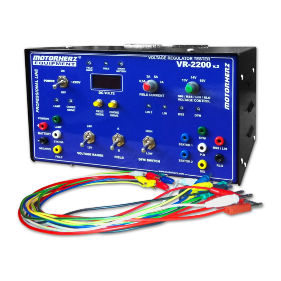
- Page 1 VOLTAGE REGULATOR TESTER MOTORHERZ VR-2200 v.2 OPERATION MANUAL VR - 2200 v.2 2018...
-
Page 2: Table Of Contents
CONTENTS Introduction ........................3 1. Description and principle of operation ................. 3 1.1. Application ....................3 1.2. Voltage regulators overview ................3 1.3. Specifications ....................5 1.4. Tester design ....................5 2. Device operation ......................8 2.1. Operating limitations ..................8 2.2. -
Page 3: Introduction
This Operation Manual is intended to familiarize the staff and customers with the specifications, design, principle of operation, terms of service, maintenance, storage and transportation of voltage regulators Tester MOTORHERZ VR-2200 v.2 (hereinafter – tester), intended for diagnostic troubleshooting of the automotive vehicles voltage regulators. - Page 4 Figure 1. a) dependence of alternator voltage Ud and current rate Iв at rotor operating speed in a drive winding; b) dependence of alternator voltage Ud and current rate Iв at load current Iн in a drive winding. 1.2.4. Any voltage regulator contains: - receiving alternator voltage sensing element, (usually volt box on a regulator input);...
-
Page 5: Specifications
Specifications. 1.3. Table 1. Parameter Parameter value 1. Tester type portable, desktop 2. Tester power supply Alternating-current monophase network with grounded conductor 2.1. Voltage, V 230±10 2.2. Frequency, Hz 50 ±0.5 3. Rated energy input, W, no more than 4. Congestion safety in power supply circuit fusible safety device (2А) ВATTERY / POSITIVE (+) , 5 . - Page 6 1.4.4. The housing has a sound collected from a bent sheet metal structure. The front part of the housing has a control panel and display. 1.4.4.1. There is provided a holes on the side walls for ventilating electrical equipment disposed in the housing. 1.4.4.2.
- Page 7 Table 2. Pos. Control element Type of Color Functionality marking control 1 DC VOLTAGE Tumbler iron-grey Selection of voltage appropriate of checked RANGE regulator (12V, 24V) Selection of regulator checked type А or В Tumbler iron-grey A/B FIELD iron-grey DFM HIGH / DFM Mode key of regulator control with output DFM.
-
Page 8: Device Operation
BATTERY POSITIVE NEGATIVE. Note. The electrical circuit for the test bench is the developer’s intellectual property and is not shared with third parties. If you have any questions, please contact your nearest Motorherz Equipment sales representative. 2. Device operation. Operating limitations. -
Page 9: Pre-Operation
2.1.3. Environment - temperature from plus 10 to plus 40 ° C, humidity (65 ± 20)%, atmosphere pressure (765 ± 30) mm Hg. 2.1.4. Tester must be connected only to a single phase circuit with the protective grounding conductor. 2.1.5. Personnel, admitted to the operation of the test bench, must study this Operation Manual, be trained in accordance with the correspondent qualification profile and safety trained with registration in the appropriate journal. -
Page 10: The Diodes Integrated Control
Symbolic notation of the modern generators voltage regulator outputs are shown in Appendix B. A vehicle system voltage and a voltage of cut-off stabilization (such voltage has sizable fluctuation for different diode types) are marked in catalogs. 2.3.3. Usable regulator must have a stabilization voltage corresponding to the specified in paragraph 2.4.3.2. 2.3.4. -
Page 11: Safety Measures
2.4.4.4. Switch tumbler POWER, in position , flashing indicator will switch on a stabilization FIELD voltage value will appear on digital display. in position 3 А increasing load current in rotor winding. During usable 2.4.4.5. Turn key FIELD CURRENT regulator control, stabilization voltage value should remain on digital display. Acceptable voltage deviation is no more than 0,1 V. -
Page 12: Maintenance
3.4. Used as a link between the checked item and a tester removable probes must comply with the requirements according to GOST IEC 61010-031. 3.5. Personnel, admitted to the test bench operation must study its structure, operating conditions and these safety requirements. -
Page 13: Disposal
Replace the digital display In the event of other faults please contact your nearest “Motorherz Equipment” trade representative. - Page 14 APPENDIX B (obligatory) TYPE CODES FOR THE TERMINALS OF THE GENERATOR VOLTAGE REGULATOR "A" – the same as "IG"; "I" (Ignition) – ignition on\off input. "AS" (Alternator Sense) – (Ford) – the same as "S"."B+" – батарея (+). "B+" – battery (+). "B–"...
Need help?
Do you have a question about the VR-2200 v.2 and is the answer not in the manual?
Questions and answers