Table of Contents
Advertisement
Advertisement
Table of Contents
Troubleshooting

Summary of Contents for Aura Systems AuraGen
- Page 1 ® AURAGEN INDUCTION POWER SOURCE WNER’S ANUAL M1120221-3 Date: 090630...
- Page 3 Typical Under-Hood Installation Hydraulically Driven Power Take Off (PTO) Driven...
- Page 4 Unlike typical portable generator sets which run at a constant engine speed (usually 3,600 RPM), the AuraGen systems produces clean, pure sine wave, 60 or 50 Hz electrical power at any en- gine RPM. The output voltage and frequency will not fluctuate due to momentary or sustained changes in engine speed.
-
Page 5: Table Of Contents
... 26 (Cont’d) ALL-AC, ALL-DC, AC/DC/ENGINE-OFF INVERTER CHARGER SYSTEM ... 27 (Cont’d) AURAGEN/VIPER SINGLE & DUAL G8500YC INVERTER CHARGER SYSTEM... 28 AURAGEN LIMITED WARRANTY ..................29 WARRANTY SERVICE OR REPAIR .................. 29 OWNER’S RESPONSIBILITY ..................29 NORMAL WEAR ......................29 RETURN PROCEDURE .................... -
Page 6: Thank You For Choosing Our Product
CUSTOMER RECORD On your AuraGen system components, you will find the model number and serial number on the labels adhered to the AuraGen cover plate and side of the ECU. We recommend you record these numbers in the space provided below. Refer to them should you need to contact your authorized AuraGen Distributor/dealer regarding this product. -
Page 7: The Auragen Systems
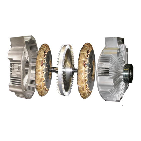
THE AURAGEN SYSTEMS (U.S. Patents No. 5,734,217 and 6,157,175) The AuraGen System includes: (Also see diagrams on pages 3-5) • Induction Power Source • Electronic Control Unit (ECU) • Control Panel • Idle Control Unit (some vehicles) • Mounting hardware and cables... - Page 8 Optional Equipment Available: • Remote Power Strip • Manual Transfer Switch Remote Power Strip Manual Transfer Switch Ask your authorized AuraGen Distributor/dealer about the optional equipment. 3 - Owner’s Manual M1120221-3, 090630...
-
Page 9: Diagram Of Typical Auragen Vehicle Installation
M1120221-3, 090630 Owner’s Manual - 4... -
Page 10: Diagrams Of Specific Auragen Systems
All-AC: Provides 120 VAC power to GFI outlets and/or 240 volt outlets. An optional remote power strip with 120 VAC and/or 120/240 VAC service is also offered. AC/DC: Provides 120 VAC power to GFI outlets and 14 or 28 VDC connected to the vehicle batteries. - Page 11 All-DC: Provides 14 or 28 VDC to auxiliary batteries. No AC service is available. Inverter Charger System (ICS): Provides 120 or 240 VAC and 14 or 28 VDC power with or without engine running. An optional remote power strip with 120 or 240 VAC service is also offered.
-
Page 12: Safety Precautions
• DO NOT change pulley types or sizes as the Induction Power Source could exceed its 12,000 RPM limit resulting in possible component and/or system failure. • DO NOT open or dismantle the AuraGen Induction Power Source, the Electronic Control Unit (ECU), or any other components of the AuraGen system. -
Page 13: Exhaust Gases
• Use extreme caution when working with live electrical components. High voltage can cause injury or death. • DO NOT connect the AuraGen Electronic Control Unit (ECU) directly to any building electrical system. Differing voltages between the AuraGen and the utility line create a potential for elec- trocution or property damage. -
Page 14: General Operating Instructions
1. The AuraGen Control Panel is typically located under the dashboard. 2. When the engine is started the AuraGen system will automatically start. 3. Verify that the green POWER LED illuminates. The POWER LED will flash at first as the system engages, then remain on continuously indicating proper operation. -
Page 15: Inverter/Charger System
AC power ON and OFF. It has four LED lights labeled BAT for auxiliary battery(s), GEN for AuraGen, CHG for battery charger, and AC for AC out- put. All LEDs are system-active dependent and combine to indicate ICS and component operational status. -
Page 16: Operation While Stationary
Park mode. Depending upon the vehicle and engine type, the engine RPM will increase to a constant level similar to engagement of an air conditioning compressor . If the AuraGen is operated at very high power levels for extended periods of time, the engine RPM will in- crease by up to 200 RPM to compensate for the increase in system temperature. -
Page 17: Remote Power Strip
PUTTING YOUR AURAGEN SYSTEM TO USE Your AuraGen System is a useful mobile source of 120/240 volt AC and 14/28 volt DC power, as specified from your AuraGen model. This means, within the limitations of its generating capacity, you can use it to power most electrical appliances, machines, or equipment. -
Page 18: Typical Auragen Applications
Laser Measuring Equipment POWER CAPACITY While your AuraGen system can serve as a reliable substitute for commercial power, it can only do so within the limitations of its maximum output capacity. For example, the G5000 system provides standby power of up to 6,000 watts with surge capacity of 7,200 watts for 2 seconds. -
Page 19: Wattage Requirements For Typical Appliances And Tools
G5000 which is 6,000 watts for up to 20 minutes (standby). If your AuraGen model is a G8500, you can produce up to 8,000 watts of AC power continuous or 8,500 watts for up to 20 minutes (standby). When using the AuraGen system, be careful not to overload any of the output circuits individually, or the system as a whole. -
Page 20: General Inspection
GENERAL INSPECTION Periodically check the AuraGen serpentine belt for signs of wear, fraying, and proper tension. Contact your authorized distributor/dealer if belt shows signs of wear. Also, visually inspect the Electronic Control Unit (ECU) to ensure there is nothing obstructing the airflow around the unit. -
Page 21: System Troubleshooting Guide - All-Ac, Ac/Dc And All-Dc
Low RPM Shutdown 2. Idle control faulty - R/R idle control. *1. Incorrect pulley ratio. Slow Flash Slow Flash AuraGen Overspeed *2. AuraGen rotor exceeded factory (Alternating) (Alternating) speed specifications. 1. Temp sense connector not AuraGen Temp Sense connected - connect. - Page 22 1. Faulty temp sensor - R&R AuraGen. Fast Flash Slow Flash Wiring Failure 117, 118 2. Internal AuraGen wiring incorrect - R&R AuraGen. 1. Faulty ECU - R&R ECU. Fast Flash Fast Flash Inverter 0 or 180 Overload 49, 50 2.
-
Page 23: System Troubleshooting Guide - Inverter/Charger System
1. Temp sense connector not connected - Yellow AuraGen Temp Sense ECU=145 connect. Slow Flash Open 2. Temp sensor open - R&R AuraGen. 1. AuraGen not getting sufficient Yellow AuraGen Over- ECU=113 ventilation - provide additional ventilation. Fast Flash temperature 2. - Page 24 Slow Flash engine and check for proper charging. Otherwise, check voltage across battery and if below 10V, charge batteries from external source or replace battery. 1. AuraGen power cable wiring problem – correct wiring. Battery Over-current ICS=501 Fast Flash 2. AC Load over-surge.
-
Page 25: Auragen System Specifications
AURAGEN SYSTEM SPECIFICATIONS The following specifications define the power output, capacities, and performance of the indicated AuraGen system. AuraGen System Specification - All-AC ALL-AC SYSTEMS - 5000 AND 8000 WATT AURAGEN MODELS G5000/G5000M G8500/G8500M (12 OR 24 VDC VEHICLE) (12 OR 24 VDC VEHICLE) -
Page 26: Ac/Dc
AuraGen System Specification - AC/DC AC/DC SYSTEMS - 6000 AND 7000 WATT AURAGEN MODELS G6000D/G6000DM G7000D/G7000DM (12 OR 24 VDC VEHICLE) (12 OR 24 VDC VEHICLE) 5800 WATTS 7000 WATTS STANDBY POWER (20 MINUTES) TOTAL POWER 5300 WATTS 6800 WATTS... -
Page 27: All-Dc
AuraGen System Specification - G6000D All-DC ALL-DC SYS TEM - 6000 W ATT AURAGEN MODEL G6000D/G6000DM 24 VDC VEHICLE STA NDBY POWER (20 MINUTES) TOTAL POWER CONTINUOUS POWER 5600 WA TTS A C POWER (CONTINUOUS) A C STA NDBY (20 MINUTES) -
Page 28: 6000X Inverter/Charger
AuraGen System Specification - G6000X Inverter Charger INVERTER CHARGER (ICS) - 5000 WATT AURAGEN MODELS G6000X/G6000XM G6000X/G6000XM (12 VDC VEHICLE) (24 VDC VEHICLE) STANDBY POWER (20 MINUTES) 6000 WATTS 6000 WATTS TOTAL POWER 5000 WATTS 5000 WATTS CONTINUOUS POWER 5000 WATTS... -
Page 29: 8500X Inverter/Charger
AuraGen System Specification - G8500X Inverter Charger INVERTER CHARGER (ICS) - 8000 WATT AURAGEN MODELS G8500X/G8500XM G8500X/G8500XM (24 VDC VEHICLE) 12 VDC VEHICLE) 8500 WATTS 8500 WATTS STANDBY POWER (20 MINUTES) TOTAL POWER 8000 WATTS 8000 WATTS CONTINUOUS POWER AC POWER (CONTINUOUS) -
Page 30: All-Ac, All-Dc, Ac/Dc/Engine-Off Inverter Charger System
All-AC, All-DC, AC/DC/Engine-Off Inverter Charger System Product Line and Specifi cations All-AC G5000 G8500 AURAGEN PRODUCTS STANDBY POWER (20 MINUTES) 6000 WATTS 6000 WATTS 8500 WATTS 8500 WATTS TOTAL POWER CONTINUOUS POWER 5000 WATTS 5000 WATTS 8000 WATTS 8000 WATTS... -
Page 31: All-Ac, All-Dc, Ac/Dc/Engine-Off Inverter Charger System (Cont'd)
All-AC, All-DC, AC/DC/Engine-Off Inverter Charger System Product Line and Specifi cations (cont’d) M1120221-3, 090630 Owner’s Manual - 26... - Page 32 All-AC, All-DC, AC/DC/Engine-Off Inverter Charger System Product Line and Specifi cations (cont’d) AC/DC/ENGINE-OFF SILENT WATCH (INVERTER CHARGER SYSTEM [ICS]) G6000X 24 VDC G8500X 24 VDC AURAGEN PRODUCTS STANDBY POWER (20 MINUTES) 6000 WATTS 6000 WATTS 8500 WATTS 8500 WATTS TOTAL POWER...
-
Page 33: Auragen/Viper Single & Dual G8500Yc Inverter Charger System
AuraGen/VIPER Single and Dual G8500YC Inverter Charger System Confi guration Specifi cations AC-DC/ENGINE-OFF SILENT WATCH [24VDC] (INVERTER CHARGER SYSTEM [ICS]) SINGLE G8500YC G8500X 24 VDC DUAL* G8500YC AURAGEN PRODUCTS STANDBY POWER (20 MINUTES) 8500 WATTS 8500 WATTS 17000 WATTS 17000 WATTS... -
Page 34: Auragen Limited Warranty
LIMITED WARRANTY ® Aura Systems, Inc. (“Aura”) warrants to the end user that this product shall be free from defects in materials and workmanship for three (3) years starting from the date of initial installation, but starting no later than six (6) months from the date of product being shipped from Aura Systems, Inc. -
Page 35: Warranty Limitations
AuraGen system was originally in- stalled; or 6) product has not been installed by an certified AuraGen installer. This warranty is void if the AuraGen system is new materials, production methods and design refinements may be introduced into existing models without notice. - Page 36 Notes M1120221-3, 090630...
- Page 37 M1120221-3, 090630 Notes...
- Page 38 Notes M1120221-3, 090630...
- Page 40 1310 E. Grand Ave., El Segundo, CA 90245 Phone: 310-643-5300 Fax: 310-643-7457 Toll Free: 800-909-AURA Web Site: www.aurasystems.com...
Need help?
Do you have a question about the AuraGen and is the answer not in the manual?
Questions and answers