Table of Contents
Advertisement
Quick Links
Via Acquanera, 29
22100 Como
tel. 031.526.566 (r.a.) fax 031.507.984
info@calpower.it
www.calpower.it
June 2013
© 2013 Fluke Corporation. All rights reserved. Specifications are subject to change without notice.
All product names are trademarks of their respective companies.
SUPER-DAQ Precision Temperature Scanner
1586A
Users Manual
Advertisement
Table of Contents

Related Manuals for Fluke 1586A


Summary of Contents for Fluke 1586A
- Page 1 22100 Como tel. 031.526.566 (r.a.) fax 031.507.984 info@calpower.it www.calpower.it 1586A SUPER-DAQ Precision Temperature Scanner Users Manual June 2013 © 2013 Fluke Corporation. All rights reserved. Specifications are subject to change without notice. All product names are trademarks of their respective companies.
- Page 2 Fluke authorized resellers shall extend this warranty on new and unused products to end-user customers only but have no authority to extend a greater or different warranty on behalf of Fluke. Warranty support is available only if product is purchased through a Fluke authorized sales outlet or Buyer has paid the applicable international price.
-
Page 3: Table Of Contents
Safety Information ..................... 1-9 Screen Capture Feature ..................1-11 About this Manual ..................... 1-12 The Product Manual Set ..................1-12 How to Contact Fluke Calibration ..............1-13 Calibration and Repair Information ..............1-13 General Specifications ..................1-13 Measurement Specifications ................1-15 PRT/RTD ....................... - Page 4 1586A Users Manual Digital I/O ...................... 1-22 Totalizer ......................1-22 Trigger ......................1-22 Alarm Output ....................1-22 1586-2588 DAQ-STAQ Input Module Specifications ........1-22 General ......................1-22 1586-2586 High-Capacity Input Module Specifications ........1-22 General ......................1-22 Initial Setup and Configuration ............2-1 Introduction ......................
- Page 5 Contents (continued) Channel Delay ....................3-33 Rate of Change ....................3-33 Display As ..................... 3-34 Open Detect ....................3-34 Probe Library ..................... 3-34 Scan/Monitor, Record, and Data ............4-1 Introduction ......................4-3 Scan ........................4-3 About Scan Timing and Sampling ..............4-5 Configure a Scan ...................
- Page 6 1586A Users Manual Error Messages ....................7-3 Troubleshooting ....................7-20...
- Page 7 List of Tables Table Title Page 1-1. Front-Panel Features ....................1-5 1-2. Rear-Panel Features ....................1-7 1-3. Symbols ........................1-9 2-1. Fuses ........................2-3 2-2. Instrument Setup Menu ..................2-7 3-1. Types of Inputs ....................... 3-8 3-2. Channel Types and Numbers ................. 3-10 3-3.
- Page 8 1586A Users Manual...
- Page 9 List of Figures Figure Title Page 1-1. Screen Capture ....................... 1-11 2-1. Fuse Replacement and Line-Voltage Selection............2-3 2-2. Mains Power Cord Connection ................2-4 2-3. Handle Positions and Boot Removal ..............2-5 2-4. Main Power Switch and Standby Key ..............2-6 2-5.
- Page 10 1586A Users Manual viii...
-
Page 11: Title
Safety Information ..................... 1-9 Screen Capture Feature ..................1-11 About this Manual ..................... 1-12 The Product Manual Set ..................1-12 How to Contact Fluke Calibration ..............1-13 Calibration and Repair Information ..............1-13 General Specifications ..................1-13 Measurement Specifications ................1-15 PRT/RTD ....................... - Page 12 1586A Users Manual General ......................1-22 1586-2586 High-Capacity Input Module Specifications ........1-22 General ......................1-22...
-
Page 13: Introduction
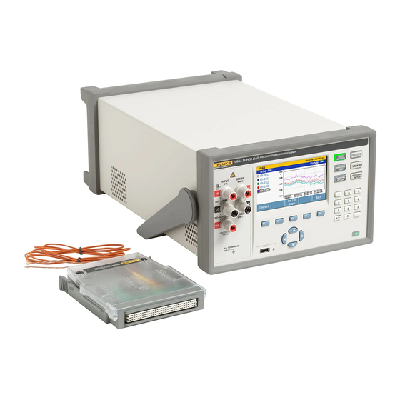
Product Overview The Fluke Calibration 1586A SUPER-DAQ Precision Temperature Scanner (the Product or Instrument) is a 45 analog channel bench-top measurement instrument that measures and records temperature, resistance, dc volts, and dc current (see Table 1-1). See the Specifications section for information on the types and ranges of the measurement inputs the Product can accept. - Page 14 USB or LAN TCP/IP connection. • Automated Sensor Test – Automatically sets the temperature of a Fluke Calibration dry-well calibrator or temperature bath connected to the rear-panel RS-232 port. Monitors temperature stability, and measures the readings of temperature sensors and a reference thermometer when the temperature is stable.
-
Page 15: Front And Rear-Panel Overview
Product Overview and Specifications Front and Rear-Panel Overview Front and Rear-Panel Overview Table 1-1 identifies and describes the front-panel features and Table 1-2 identifies and describes the rear-panel features. Table 1-1. Front-Panel Features hcn001.eps Item Name Function Puts the Product in the standby mode. In standby, the display is off and Standby Key the keys are disabled. - Page 16 1586A Users Manual Table 1-1. Front-Panel Features (cont.) Item Name Function Red LED that illuminates when the USB drive is recognized and flashes red when data is transferred to or from the USB drive. USB Data Transfer Caution ...
- Page 17 Product Overview and Specifications Front and Rear-Panel Overview Table 1-1. Front-Panel Features (cont.) Item Name Function Starts and stops data recording. When recording, the key illuminates and “RECORDING” shows on the top of the display. Recording can be set to automatically start and stop with a scan.
- Page 18 See Source Control “Automated Test” in Chapter 4. USB port used for remote operation. See the 1586A Remote Programmers Serial USB Port Guide. Network port used for remote operation. See the 1586A Remote LAN Connection ...
-
Page 19: Safety Information
Directive Annex I, this product is classed as category 9 "Monitoring and Control Instrumentation” product. Do not dispose of this product as unsorted municipal waste. Go to Fluke’s website for recycling information. Product conforms with the requirements of the applicable EC directives. - Page 20 1586A Users Manual • Use the Product only as specified, or the protection supplied by the Product can be compromised. • Examine the case before you use the Product. Look for cracks or missing plastic. Carefully look at the insulation around the terminals.
-
Page 21: Screen Capture Feature
The display shows “File Saved”. 3. Remove the USB from the front panel and connect it to a USB drive on a PC. 4. Open the USB drive and navigate to the image folder with this path: \\fluke\1586A\[Product Serial Number]\Image PRINT 3 seconds hcn024.eps... -
Page 22: About This Manual
• The 1586A Calibration Manual contains calibration and adjustment procedures to keep the Product within specifications. • The 1586A Product CD contains the all the manuals in the manual set. All manuals are online at http://www.flukecal.com/ and on CD. -
Page 23: How To Contact Fluke Calibration
Calibration and Repair Information To schedule and send the Product to Fluke for calibration or repair: 1. Contact the Fluke Service Center in your area to schedule the calibration or repair (see “Contact Fluke Calibration”). 2. Pack and secure the Product in a shipment box with a minimum of 2 inches of packing around the Product to prevent damage. - Page 24 1586A Users Manual Altitude Operating ............2,000 m Storage ............... 12,000 m Vibration and Shock ..........Complies with MIL-PRF-28800F Class 3 Channel Capacity Total analog channels ........45 Voltage/resistance channels ....... 41 Current channels ..........5 Digital I/O ............8 bits Totalizer ..............
-
Page 25: Measurement Specifications
Product Overview and Specifications Measurement Specifications Measurement Specifications Accuracy specifications generally apply with medium and slow sample rates (unless otherwise noted), after a warm-up time of 1 hour, and within an environment temperature range of 18 °C to 28 °C, and may depend on the channel. The confidence level for accuracy specifications is 95 % within 1 year of calibration. -
Page 26: Prt/Rtd Temperature Accuracy
1586A Users Manual PRT/RTD Temperature Accuracy Accuracy is for 4-wire 100 Ω nominal PRT/RTD, using medium or slow sample rate. When using 3-wire PRT/RTD add 0.039 °C to the accuracy specification for internal resistance mismatch and voltage offset if using Channel 1, or add 0.15 °C if using channels x01 through x20. -
Page 27: Thermistor Temperature Accuracy
Product Overview and Specifications Measurement Specifications Thermistor Temperature Accuracy Accuracy specifications are for 4-wire thermistor. When using 2-wire thermistor, add the number given in the table to the specification for internal resistance. If the environment temperature is outside the specified range, increase the accuracy specification by 25 % for every 1 °C outside the specified environment temperature range. -
Page 28: Thermocouple
1586A Users Manual Thermocouple Temperature Range ..........−270 °C to 2315 °C (depending on the sensor) Voltage Range ............−15 mV to 100 mV Thermocouple Voltage Accuracy Accuracy is given as ± (|% of measurement| + μV). Basic accuracy specification is for medium or slow sample rate. When using a fast sample rate add the number given in the table to the accuracy specification. -
Page 29: Thermocouple Measurement Characteristics
Product Overview and Specifications Measurement Specifications Accuracy Type Fixed / External CJC Internal CJC Temperature (Range) High-Capacity Channel 1 Ch. x01 – x20 DAQ-STAQ Module Module −200 °C 0.17 °C 0.25 °C 0.64 °C 1.42 °C 0 °C 0.07 °C 0.10 °C 0.27 °C 0.61 °C... -
Page 30: Dc Voltage
1586A Users Manual DC Voltage Maximum Input ............50 V on any range Common Mode Rejection ........140 dB at 50 Hz or 60 Hz (1 kΩ unbalance in LOW lead) ±50 V peak maximum Normal Mode Rejection ........55 dB for power line frequency ±0.1 %, ±120 % of range peak maximum A/D Linearity ............ -
Page 31: Dc Current Input Characteristics
Product Overview and Specifications Measurement Specifications DC Current Input Characteristics Resolution Range Burden Voltage Slow / Medium Fast ±100 μA 0.1 nA 1 nA <1 mV ±1 mA 1 nA 10 nA <1 mV ±10 mA 10 nA 100 nA <1 mV ±100 mA 100 nA... -
Page 32: Digital I/O
1586A Users Manual Digital I/O Absolute Voltage Range ......... -4 V to 30 V Input Minimum Logic High ........2.0 V Input Maximum Logic Low ........0.7 V Output Type ............open drain active low Output Logic Low (<1 mA) ........0 V to 0.7 V Maximum Sink Current ........... -
Page 33: Initial Setup And Configuration
Chapter 2 Initial Setup and Configuration Title Page Introduction ......................2-3 Set the Regional Voltage ................... 2-3 Connect to Mains Power ..................2-4 Set the Handle Position ..................2-5 Power On and Standby ..................2-6 Warm-Up the Product ..................2-7 Configure the Product .................. - Page 34 1586A Users Manual...
-
Page 35: Introduction
See Chapter 6 for instructions on how to change the fuse. Each voltage selection requires a specific fuse. See Table 2-1. Table 2-1. Fuses Voltage Selector Fuse Fluke Part Number 100 V 0.25 A, 250 V (slow blow) 166306 120 V 0.25 A, 250 V (slow blow) -
Page 36: Connect To Mains Power
1586A Users Manual Connect to Mains Power Use the mains power cord to connect the Product to a 100 V ac, 120 V ac, or 230 V ac nominal outlet as shown in Figure 2-2. Warning To prevent possible electrical shock, fire, or personal injury: •... -
Page 37: Set The Handle Position
Initial Setup and Configuration Set the Handle Position Set the Handle Position The handle is used to easily transport the Product but can also be used as a stand. Figure 2-3 shows the various handle positions and also shows how to remove and install the handle and the protective rubber boots. -
Page 38: Power On And Standby
1586A Users Manual Power On and Standby As shown in Figure 2-4, the Product has a main power switch located on the rear panel that supplies power to the unit, and a Standby key () on the front panel that puts the Product in a standby mode. -
Page 39: Warm-Up The Product
Initial Setup and Configuration Warm-Up the Product Warm-Up the Product It is recommended that the Product be warmed up before use to stabilize the environmentally controlled components. This will ensure the best performance to the specification listed in Chapter 1. Sufficient warm-up times are as follows: •... -
Page 40: Input Module And Relay Card Installation
Change the wait time or disable the screensaver. 60 Min Calibration Shows the date that the Product was last calibrated. See Date the 1586A Calibration Manual for more information. Password See “Set Up Security” in this Change the Admin and User profile passwords. Management chapter for more information. - Page 41 Initial Setup and Configuration Input Module and Relay Card Installation To install the Input Module: 1. Power off the Product with the main power switch. 2. Slide an Input Module into the slot the relay card was installed. 3. Power on the Product with the main power switch. 4.
- Page 42 1586A Users Manual hcn018.eps Figure 2-6. Relay Card Installation 2-10...
-
Page 43: Install A Daq-Staq Multiplexer Connection Module
Initial Setup and Configuration Install a DAQ-STAQ Multiplexer Connection Module Install a DAQ-STAQ Multiplexer Connection Module In order to use an additional DAQ-STAQ Multiplexer Connection Module (the Multiplexer), an interface relay card must be installed. Use the procedure below and refer to Figure 2-7 as necessary. - Page 44 1586A Users Manual hcn032.eps Figure 2-7. DAQ-STAQ Multiplexer Installation 2-12...
-
Page 45: Set Up Security
To protect the Product from accidental or unintentional changes to the calibration coefficients. The Admin profile is the only profile that can open the Calibration menu to calibrate the Product. Refer to the 1586A Calibration Manual for calibration and adjustment instructions. - Page 46 1586A Users Manual 2-14...
-
Page 47: Input And Channel Configuration
Chapter 3 Input and Channel Configuration Title Page Introduction ......................3-3 Input Wiring ....................... 3-3 The 1586-2586 High Capacity Input Module ..........3-3 The 1586-2588 DAQ-STAQ Multiplexer Connector Module ...... 3-4 Wiring Safety and Considerations ..............3-5 3-Wire and 4-Wire Sense Input Configuration ..........3-6 Input Types and Wiring Diagrams .............. - Page 48 1586A Users Manual...
-
Page 49: Introduction
Input and Channel Configuration Introduction Introduction This chapter supplies instructions on how to wire inputs to the Input Module then configure the associated channel. Input Wiring The 1586-2586 High Capacity Input Module The 1586-2586 High Capacity Input Module (the Input Module) is used to wire inputs of various types to the Product (see Figure 3-1). -
Page 50: The 1586-2588 Daq-Staq Multiplexer Connector Module
1586A Users Manual The 1586-2588 DAQ-STAQ Multiplexer Connector Module The 1586-2588 DAQ-STAQ Multiplexer Connector Module (the Multiplexer) is an external, bench-top accessory that is used to quickly wire inputs of various types to the Product (see Figure 3-2). Each Multiplexer has 20 analog channels (ChX01 through ChX20) that can be configured to measure temperature, resistance, and dc volts. -
Page 51: Wiring Safety And Considerations
Input and Channel Configuration Input Wiring Wiring Safety and Considerations Warning To prevent possible electrical shock, fire, or personal injury: • Consider all accessible channels to be hazardous live and an electric shock hazard if any channel is connected to a hazardous voltage source. -
Page 52: 3-Wire And 4-Wire Sense Input Configuration
1586A Users Manual 3-Wire and 4-Wire Sense Input Configuration For improved resistance measurement accuracy, the Product can connect to 3-wire (PRT only) and 4-wire instruments with sense connections. Sense connections cancel out the resistance of the test lead or wire and significantly improves the accuracy of the measurement. -
Page 53: Input Types And Wiring Diagrams
Input and Channel Configuration Input Wiring Sense wires connected directly across from source on Channel 116. Source on Channel 106. Note: For 3-Wire connections, leave the H sense open. 3-Wire or 4-Wire Function Channel Reserved hcn014.eps Figure 3-3. 3-Wire and 4-Wire Channel Reservation Input Types and Wiring Diagrams Table 3-1 lists the type of input types the Product can measure and the wiring polarity that should be used to wire it to the Input Module. -
Page 54: Input Wiring Instructions
1586A Users Manual Table 3-1. Types of Inputs Channel Type of Input Range and Types Configuration Wiring Polarity Reference DC Voltage Range: 0 V to 50 V Page 3-19 DC Current Range: 0 mA to 100 mA Page 3-19 2-Wire or 4-Wire 2-Wire Resistance (Ω) - Page 55 Input and Channel Configuration Input Wiring 2. Squeeze together the release tabs located on both sides of the Input Module then pull the module out of the Product. 3. Use a straight-head screw driver to rotate the cover locks to the unlock position then open the cover.
-
Page 56: Channel Configuration
1586A Users Manual Channel Configuration This section contains instructions on how to configure the channels after the inputs are connected to the Input Module. About Channel Numbers A channel number (Ch) is a numerical identification associated with a set of terminals on the Input Module. - Page 57 Channel Configuration Slot: Channel 101 - 122 Slot: Channel 201 - 222 Rear View Front View 1586A T-DAQ PREC 0 1 2 3 4 5 6 7 1 2 3 4 5 6 7 8 0 1 2 3 4 5...
-
Page 58: Basic Channel Operations
1586A Users Manual Basic Channel Operations Use the instructions in this section to perform basic channel operations. Open the Channel Setup Menu The Channel Setup menu lets the user manage channels, verify inputs, and also set up tests. To open the menu, push on the front panel. -
Page 59: Set Channels To On Or Off
Input and Channel Configuration Channel Configuration Table 3-3. Channel Setup Menu (cont.) Item Function Channel status indicator. When a channel is set to ON, the channel status indicator is green. When OFF, the channel status indicator is white. Channel selection indicator. When a channel is selected, the channel information shows on the screen. -
Page 60: Verify A Channel
1586A Users Manual The display opens a channel configuration sequence that prompts the user to select key parameters for the specific channel type. These sequences are shown and described in the analog channel configuration section that starts on page 3-18. -
Page 61: Copy A Channel
Input and Channel Configuration Channel Configuration . 2. Push 3. Push or to highlight a channel. 4. Push to edit the channel. 5. Push to open the Verify Channel menu. 6. Push to zero the channel. A confirmation message appears, select OK to continue or Cancel to disregard the changes and return to previous menu. -
Page 62: Save Or Load A Channel Configuration (Setup File)
1586A Users Manual 3. Set the channel to ON if necessary. 4. Push to open the Copy Channel menu. 5. Use or to highlight a channel then push to select the channels to paste to. 6. Push to paste the channels. - Page 63 Input and Channel Configuration Channel Configuration 5. Choose Setup Files then push . 6. Use the and keys to select the file to be copied. 7. Push to manage the file. 8. Push to copy to the USB drive. Note Do not remove the USB drive until you see a file transfer complete message.
-
Page 64: Reset The Channel And Test Configuration
1586A Users Manual Reset the Channel and Test Configuration To reset the entire channel configuration and test setup: Note All channels are set to the default settings when reset and cannot be restored unless the configuration was saved. 1. Push and hold for 3 seconds. -
Page 65: Current And Voltage Channels
Input and Channel Configuration Channel Configuration 4. After the channel is configured, verify that the channel is configured properly and reading the input. For instructions, see “Verify a Channel” on page 3-14. Current and Voltage Channels Refer to Table 3-4 to configure a dc voltage or current channel. Note Ch001 can be set up for all measurements. -
Page 66: Resistance Channels
1586A Users Manual Resistance Channels Refer to Table 3-5 to configure a resistance channel. Table 3-5. Resistance Channel Configuration hcn008.eps Item Function Resistance function selection. Set up the channel for a 2-wire or 4-wire resistance measurement connection. See “Sense Input ... -
Page 67: Thermocouple Channels
Input and Channel Configuration Channel Configuration Thermocouple Channels Refer to Table 3-6 to configure a thermocouple channel. Thermocouple types R and S have optional correction polynomial coefficients to be entered. The correction equation is as follows: Δ where t is the temperature in °C and ΔV is the correction in millivolts. If the correction is not used, leave the coefficients set to 0. -
Page 68: Thermistor Channels
1586A Users Manual Thermistor Channels Refer to Table 3-7 to configure a thermistor channel. The R(T) polynomial type requires polynomial coefficients to be entered. The thermistor characterization polynomial is as follows: Where t is the temperature in °C and R is the resistance in Ω. Any coefficients that are not used must be set to 0. -
Page 69: Prt Channels
Input and Channel Configuration Channel Configuration PRT Channels Refer to Table 3-8 to configure a Platinum Resistance Thermometer (PRT) channel. ITS-90 type requires deviation function coefficients to be entered. Coefficient "A" should be set to the value of “a7” or “a8” as shown on the PRT calibration certificate. Likewise, "B"... -
Page 70: Digital I/O (Dio) Channel Configuration (Ch401)
“Digital I/O” in Chapter 1. The DIO channel will be read-only when it is set to ON (active). With a remote command, the Product can output an 8-bit TTL value. See the 1586A Remote Programmers Guide for more information. Terminal Function... -
Page 71: Totalizer Channel Configuration (Ch402)
Input and Channel Configuration Channel Configuration 3. Set channel 401 to ON (see “Set Channels to ON or OFF” on page 3-13). 4. Assign a label to the channel if desired. 5. To measure the DIO, monitor channel Ch401 in the Scan/Monitor menu. The 8-bit TTL value is shown on the display and the decimal equivalent will be recorded to the data file. - Page 72 1586A Users Manual Set up a totalizer channel as follows (see Table 3-9): 1. Connect the wire to the TOT terminal of the plug then insert the plug into the rear- panel DIO/TOT port. 2. Set the channel to ON (see “Set Channels to ON or OFF” on page 3-12). When the channel is set to ON, a channel configuration sequence shows on the display that steps the user through an initial configuration sequence as shown in Table 3-9.
-
Page 73: Math Channel Configuration (Ch501 To Ch520)
Input and Channel Configuration Channel Configuration Math Channel Configuration (Ch501 to Ch520) The Product has 20 math channels that lets the user apply a math conversion to a single channel or to a range of channels through the use of preset math functions. Table 3-10 lists the math functions available for use. - Page 74 1586A Users Manual Table 3-10. Math Channel Formulas (cont.) Formula Equation Description Calculates the reciprocal of a variable. The argument 1 / A 1 / A cannot be 0 or the result will be "+OL". Adds the readings of two source channels. This is useful...
- Page 75 Input and Channel Configuration Channel Configuration Table 3-11. Math Channel Configuration hcn020.eps Item Function Math formula selection. Channel selection for the first base channel “A”. Channel selection for the second base channel “B”. Note Only channels “A” and “B” are shown in the example because the sum math formula only combines two channels.
-
Page 76: Mx+B, Alarms, And Channel Options
1586A Users Manual Mx+B, Alarms, and Channel Options The subsequent sections supply information and procedures on how to apply Mx+B scaling, set up channel alarms, and configure additional channel options. Mx+B Scaling Mx+B is a calculation that can be applied to a channel to scale a measurement value. This feature is useful in applications where an input measurement needs to be converted to a different unit or value to simulate an output. -
Page 77: Hi And Lo Channel Alarms
Input and Channel Configuration Mx+B, Alarms, and Channel Options The Product uses the offset to zero a channel. To do this, the Product calculates the offset required to convert the measurement to a zero value, sets Mx+B to ON, and loads the calculated offset value into the Mx+B settings. - Page 78 1586A Users Manual 5. Highlight High or Low then push . 6. Use the numeric keypad to input the limit ( Setpoint ). 7. To turn on an alarm output: a. Highlight Output the then push . b. Highlight an alarm output to assign to the channel then push .
-
Page 79: Channel Delay
Input and Channel Configuration Mx+B, Alarms, and Channel Options Channel Delay A channel delay is a measurement time delay that can be individually assigned to each channel to delay the measurement. Channel delays can be used for various applications, but they are most useful in applications where the source impedance or circuit capacitance is high. -
Page 80: Display As
1586A Users Manual Display As Located in the Channel Options menu, use this setting to change the type of measurement of a temperature sensor. Available options change with the channel type selected. Selections available: • temperature or the compensated mV equivalent for thermocouple channels. - Page 81 Input and Channel Configuration Probe Library 5. Push to input a new probe. 6. Select Label and push to set a custom label or push to read the label from the channel. 7. Select Function and push to change. Use the on-screen options to configure the probe.
- Page 82 1586A Users Manual 3-36...
-
Page 83: Scan/Monitor, Record, And Data
Chapter 4 Scan/Monitor, Record, and Data Title Page Introduction ......................4-3 Scan ........................4-3 About Scan Timing and Sampling ..............4-5 Configure a Scan ................... 4-6 Trigger Type....................4-7 Auto Recording ..................4-8 File Destination ..................4-8 Sample Rate ....................4-8 Data Security ..................... - Page 84 1586A Users Manual...
-
Page 85: Introduction
Scan/Monitor, Record, and Data Introduction Introduction This chapter supplies information on the Scan, Monitor, and Record functions along with procedures and instructions. Scan Scan is a function of the Product that sequentially measures each channel and either temporarily shows the data on the display or records it to file if the recording feature is enabled (see “Record”... - Page 86 1586A Users Manual hcn045.eps Figure 4-1. Scan Data The Scan menu lets the user control the scan and view the scan data. The Scan menu also shows important status indicators to quickly inform the user of the scan status and progress of the scan.
-
Page 87: About Scan Timing And Sampling
Scan/Monitor, Record, and Data Scan Table 4-1. The Scan Menu (cont.) Item Function Master alarm indicator that displays when any configured channel alarm is tripped while a scan is in progress. To see which alarm tripped, push on the Scan menu to open the channel data. ... -
Page 88: Configure A Scan
1586A Users Manual • The total channel sample time is the minimum sample time plus the user- programmed channel delay. The longer the channel delay, the longer it takes to sample the channel. • The total scan sweep time is sum of the channel sample times of all the channels scanned. -
Page 89: Trigger Type
Scan/Monitor, Record, and Data Scan hcn036.eps Figure 4-3. Test Setup Menu Example Trigger Type The Trigger Type tells the Product when and how to start and stop a scan. There are four trigger types: Note If a Scan Count of 0 is set or if the scan interval is shorter than the scan sweep time, the scan continuously repeats until the scan is stopped or the Product runs out of memory. -
Page 90: Auto Recording
1586A Users Manual Auto Recording The Auto Recording feature automates the recording process. If Auto Recording is set to ON, the Product automatically records the scan data to file when the scan is started. If set to OFF, the user must manually push to start recording. -
Page 91: Data Security
Scan/Monitor, Record, and Data Scan Table 4-2. Scan Sample Rates Sample Time (s) Functions Range or CJC Type Fast Medium Slow 400 Ω Range 0.08 1.00 4.00 4 k Ω Range 0.20 1.00 4.00 Thermistor 2.2 k, 90k Ω Range 1.00 1.00 4.00... -
Page 92: Temperature Unit
1586A Users Manual Temperature Unit This is an overall Product setting that sets the temperature units to be shown in either Celsius or Fahrenheit. Notes • The ability to change this setting to Fahrenheit is not available in some regions. -
Page 93: Automatic Power Loss Scan Resume
Scan/Monitor, Record, and Data Scan Automatic Power Loss Scan Resume In the event that the Product experiences a loss of mains power while a scan is in progress, it can be configured to resume the scan when mains power comes on. This feature is referred to as “Power Loss Resume State”. -
Page 94: View Scan Data And Statistics
1586A Users Manual • For the Alarm trigger type: The scan sweep is triggered by an alarm that has tripped. To do this, select the Alarm trigger type in the test setup and assign a channel to be a trigger. When the scan is started, the Product automatically starts to monitor the channel set as the trigger for a tripped alarm. - Page 95 Scan/Monitor, Record, and Data Scan hcn061.eps Figure 4-4. Scan Data Table 4-3. Scan Statistics Statistic Description Maximum Maximum measurement. Minimum Minimum measurement. Average Average of all the measurements taken. A measure of the distribution of a set of data from its mean. The more spread Standard Deviation apart the data, the higher the deviation.
-
Page 96: Graph The Measurements
1586A Users Manual Graph the Measurements The Scan function has a graph feature that lets the user display the measurement data in a graph. This feature is located in the Scan menu (push then push ).The graph automatically scales to fit all the information on the display when opened. To refine the data, the graph can be manipulated with the front-panel arrow keys as shown in Figure 4-5. -
Page 97: Monitor
Scan/Monitor, Record, and Data Monitor Monitor Monitor lets the user measure a single channel between scan sweeps. In addition, the user can view statistics and a graph of the measurement data since the scan began. To monitor a channel, push on the Scan menu. When a scan is in progress, the display shows the measurement from the last reading. -
Page 98: Automated Test
To fully automate the test, the user can connect to and control a temperature source such as dry-wells, microbaths, or fluid baths from Fluke Calibration. In this configuration, the Product communicates the setpoint to the source via the RS-232 connection on the rear panel (see Figure 4-7). -
Page 99: Configure An Automated Test
Scan/Monitor, Record, and Data Automated Test Configure an Automated Test The Automated Test is a trigger type that is configured in the Test Setup menu. The options in the Automated Test setup lets the user set a series of custom temperature setpoints and select a test sequence that the Product will run without user interaction. -
Page 100: Connect To An External Source
1586A Users Manual Table 4-4. Automated Test Setup (cont.) Item Function Turn on or turn off the control source on the rear-panel that connects to an external temperature source. Set the target temperature (referred to as the setpoint). ... -
Page 101: Record
Scan/Monitor, Record, and Data Record Record The Record function saves the scan or DMM measurement results to a file that can be transferred to a PC for further evaluation. When the Product is recording data, the Record key is illuminated and “RECORDING” shows on the top of the display. Data is recorded for as long as the key is illuminated and “RECORDING”... -
Page 102: Memory Consumption For Recorded Data
5. Navigate to the data folder as follows (see Figure 4-9 for an example of the folder structure): a. Double-click on the fluke folder. b. Double-click on the 1586A folder. c. Double-click on the serial number of the Product used to record the data. In the example, 12345678 is the serial number of the Product. - Page 103 Scan/Monitor, Record, and Data Record d. Double-click on the data folder. e. Double-click on the scan folder to see scan data files or the DMM folder to see DMM data files. The data files are saved within a folder that was named with a timestamp of when the scan or measurement was recorded.
-
Page 104: How To Read The Setup Csv File
1586A Users Manual Contains all test configuration settings Measurement data hcn064.eps Figure 4-9. Setup.csv and Dat00001.csv Files How to Read the Setup CSV File The six sections of the setup.csv spreadsheet are discussed and shown in the subsequent sections. General Information This section of the spreadsheet shown below contains general information on the scan performed such as the start time and the Operator. - Page 105 Scan/Monitor, Record, and Data Record Analog Channels This section of the spreadsheet shown below contains configuration information on each analog channel that was recorded. Digital Channels This section of the spreadsheet shown below contains configuration information for the DIO channel and the TOT channel. Math Channels This section of the spreadsheet shown below contains configuration information for the math channels.
-
Page 106: How To Read The Data Csv File
1586A Users Manual How to Read the Data CSV File The dat00001.csv file contains the measurement data from the scan. Each row contains measurement data for a single scan sweep and shows the time when the sweep completed. To see how the test and channels were configured, view the information in the setup.csv file (see “How to Read the Setup.csv File”). -
Page 107: Measure/Dmm Operation
Chapter 5 Measure/DMM Operation Title Page Introduction ......................5-3 About the Measure Function ................5-3 About the DMM Function ................. 5-3 Input Type Selection and Range Adjustment ............ 5-4 Relative Measurements ..................5-4 Graph the Measurements ................... 5-5 Measurement Statistics ..................5-6... - Page 108 1586A Users Manual...
-
Page 109: Introduction
Measure/DMM Operation Introduction Introduction This chapter supplies instructions on how to operate the Measure/DMM function of the Product. About the Measure Function The Measure function lets the user quickly measure a single channel. To use this function, push on the front panel. The Measure function operates similarly to the Monitor function and has the same graphing and statistic features. -
Page 110: Input Type Selection And Range Adjustment
1586A Users Manual Input Type Selection and Range Adjustment The DMM menu has four softkeys available to select and configure the front-panel inputs for the measurement type. After a softkey is pushed, the user is prompted for additional input information to fully configure the input. To adjust the range of the measurement after the input is configured, push the and... -
Page 111: Graph The Measurements
Measure/DMM Operation Graph the Measurements Relative Measurement Value Baseline Measurement Releative Function Softkey hcn054.eps Figure 5-3. Relative Measurement Graph the Measurements The DMM has a graph feature that lets the user display the measurement data in a graph. The graph has features such as History mode and Live mode to let the user evaluate the data on the display. -
Page 112: Measurement Statistics
1586A Users Manual 4. Push to show the channel options. 5. Push to show the graph. Use and to zoom in and out. To see historical data, push to switch between History Mode and Live Mode. When in History Mode, use ... -
Page 113: Maintenance And Care
Chapter 6 Maintenance and Care Title Page Introduction ......................6-3 Clean the Product ....................6-3 Replace the Fuse ....................6-3 Memory Reset and Factory Reset ..............6-4 User-Replaceable Parts and Accessories ............6-5... - Page 114 1586A Users Manual...
-
Page 115: Introduction
To prevent possible electrical shock, fire, or personal injury, use only specified replacement parts. Table 6-1. Fuses Voltage Selector Fuse Fluke Part Number 100 V 0.25 A, 250 V (slow blow) 166306 120 V 0.25 A, 250 V (slow blow) -
Page 116: Memory Reset And Factory Reset
1586A Users Manual hcn027.eps Figure 6-1. Fuse Replacement Memory Reset and Factory Reset The Product has two memory reset functions to remove data from the memory and to reset the Product: Clear all Files and Factory Reset. See Table 6-2 for a comparison of the three functions. -
Page 117: User-Replaceable Parts And Accessories
Table 6-3 lists the part numbers of each user-replaceable part or accessory for the Product. Table 6-3. User-Replaceable Parts and Accessories Part Number Name Quantity Contact Fluke Transit Case Contact Fluke OPC Server software for 1586A Contact Fluke DIO/ALARM connectors for 1586A 4298499 USB Cable 4121552 USB Drive (4 GB) 4298486... - Page 118 1586A Users Manual...
-
Page 119: Error Messages And Troubleshooting
Chapter 7 Error Messages and Troubleshooting Title Page Introduction ......................7-3 Error Messages ....................7-3 Troubleshooting ....................7-20... - Page 120 1586A Users Manual...
-
Page 121: Introduction
Error Messages and Troubleshooting Introduction Introduction This chapter supplies information on error messages and how to troubleshoot the product. Error Messages Error messages help the user diagnose problems with the Product. Error messages contain a message along with an error code. If an error message shows on the display, use the information in Table 7-1 to resolve the problem. - Page 122 1586A Users Manual Table 7-1. Error Messages (cont.) Error Code Error Message Causes and Solutions Cause: A block data element was expected, but was invalid. For example, an END message was received before the Error -161 Invalid block data length was satisfied.
- Page 123 Error Messages and Troubleshooting Error Messages Table 7-1. Error Messages (cont.) Error Code Error Message Causes and Solutions Cause: Invalid syntax was found in the command string. Error -102 Syntax error Solution: Check the parameter value and try again. Error 0 No error Cause: Error queue is empty.
- Page 124 A/D conversion Error 200 Solution: Cycle the power. If the error occurs again, contact timeout Fluke (see Chapter 1). Cause: The line frequency is out of range. Error detecting line Error 201 Solution: Cycle the power. If the error occurs again, contact frequency Fluke (see Chapter 1).
- Page 125 1 switched. Solution: Cycle the power and try again. If the error occurs Error 208 Failed to reset relay again, the relay card needs serviced, contact Fluke (see on slot 2 Chapter 1). Error 209 Failed to reset relay...
- Page 126 Solution: Make sure that the input signal matches the match reference requirement. If the input signal is correct, cycle the power. If the error occurs again, contact Fluke (see Chapter 1). Cause: Timeout while waiting readings from inguard. Timeout waiting for Error 320 Solution: Cycle the power.
- Page 127 Error Messages and Troubleshooting Error Messages Table 7-1. Error Messages (cont.) Error Code Error Message Causes and Solutions Cause: An error occurred at present calibrating step. Error 399 Error at step %s Solution: Check next error message for specific solution. Cause: A thermocouple channel is set to external CJC, but the channel that is used to measure external CJC temperature has not been configured.
- Page 128 1586A Users Manual Table 7-1. Error Messages (cont.) Error Code Error Message Causes and Solutions Cause: TRIGger:AUTO:REF or TRIGger:AUTO:SREF command is attempting to configure an OFF channel as Reference channel reference. Error 407 not enabled Solution: Configure the channel which you want to use as reference.
- Page 129 Error 419 Read config file failed configuration can be read again. Solution: Contact Fluke. See Chapter 1. Cause: Error occurs when a user attempts to set a math channel on any channel other than Ch501 through Ch520. Error 420 Not a math channel Solution: Check the parameter value and try again.
- Page 130 1586A Users Manual Table 7-1. Error Messages (cont.) Error Code Error Message Causes and Solutions Cause: Error occurs when a user attempts to set a TOT Not a totalizer channel on any channel other than Ch402. Error 422 channel Solution: Check the parameter value and try again.
- Page 131 Error Messages and Troubleshooting Error Messages Table 7-1. Error Messages (cont.) Error Code Error Message Causes and Solutions Cause: Setpoint that is specified in the command is not in range 1 to 20. This could be because of a wrong setpoint in the TRIGger:AUTO:POINts, TRIGger:AUTO:SPOint, Error 431 Invalid setpoint...
- Page 132 Error 530 corrupt single file is corrupted or if the Instrument is malfunctioning. If the error happens with a different file, contact Fluke (see Chapter 1). Cause: Invalid accessing to state. (STA) begin not Error 580 Solution: Cycle the power.
- Page 133 LAN setup, MAC setup or calibrate constants. Error 700 NV memory invalid Solution: Default settings will be loaded, if the MAC setup or calibrate constants show failed, Contact Fluke. See Chapter Cause: Default settings have been loaded. NV invalid so default Error 701 Solution: Cycle the power.
- Page 134 Cause: Internal flash is damaged. Error reading Error 704 Solution: Cycle the power. If the error occurs again, contact calibration folder Fluke (see Chapter 1). Cause: Internal flash is damaged. Error reading Error 705 Solution: Cycle the power. If the error occurs again, contact calibration history Fluke (see Chapter 1).
- Page 135 Cause: The file has been damaged. Error 905 Error reading file Solution: Cycle the power. If the error occurs again, contact Fluke (see Chapter 1). Cause: Duplicate filename was found. Error defining setup Error 906 Solution: Try another name or remove the file with the file name conflict.
- Page 136 Cause: Input buffer overrun for communication. Communication input Error 1317 Solution: Cycle the power. If the error occurs again, contact buffer overrun Fluke (see Chapter 1). Cause: An invalid binary data parameter was found in the command. Error 1320 Invalid binary data Solution: Check the parameter and try again.
- Page 137 Cause: Failed to change file property while running SYSTem:DFU command. Error modifying file Error 1602 property Solution: Cycle the power. If the error occurs again, contact Fluke (see Chapter 1). Cause: USB drive not ready for recording or memory USB memory not operations. Error 1603 ready Solution: Install the USB drive.
- Page 138 Cause 2: Screen saver activated. Solution 2: Press any front panel key to exit the screen saver. Cause 3: Screen or unit is malfunctioning. Solution 3: Contact Fluke. See Chapter 1. Input Module is not Cause 1: Input Module not fully seated.
- Page 139 The Product starts with Cause: The SRAM battery is dead. default settings. Solution: Contact Fluke. See Chapter 1. Product is out of Cause: The internal memory or USB drive is out of space. memory. Solution: Delete or transfer some files to free up memory.
- Page 140 1586A Users Manual Via Acquanera, 29 22100 Como tel. 031.526.566 (r.a.) fax 031.507.984 info@calpower.it www.calpower.it 7-22...
Need help?
Do you have a question about the 1586A and is the answer not in the manual?
Questions and answers