Table of Contents
Advertisement
Quick Links
Advertisement
Table of Contents

Subscribe to Our Youtube Channel
Summary of Contents for De Nora Capital Controls 1041B Series
- Page 1 Instruction Manual - Series 1041B CAPITAL CONTROLS ® - 1 - 310.6002.0...
- Page 2 If you do not understand these instructions, please call De Nora Water Technologies (DNWT), Inc. for clarification before commencing any work at +1 215 997 4000 and ask for a Field Service Manager. De Nora Water Technologies, Inc.
-
Page 3: Table Of Contents
Table of Contents INTRODUCTION ..................4 General . -
Page 4: Introduction
INTRODUCTION General These instructions apply to the Series 1041 and 1041B Automatic Switchover control units. Instruction manuals for other system components and supplemental data are referenced where applicable. The Series 1041 Automatic Switchover model number describes the basic design as follows: MODEL Design/Inspection 01 - Standard... -
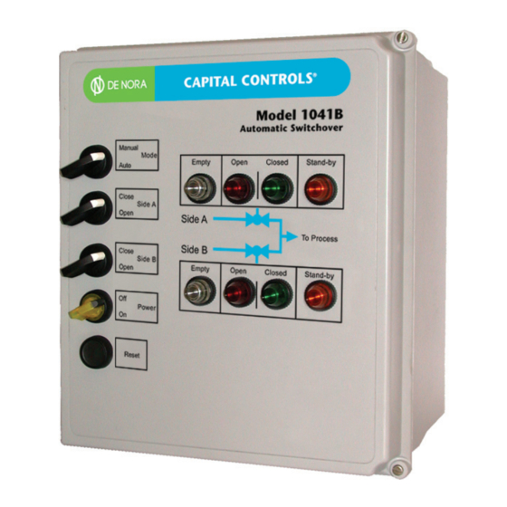
Page 5: Automatic Switchover Unit Faceplate
Automatic switchover is initiated by low pressure (high vacuum) of the on-line source and resulting switch closure. The mechanical limit switch in each motorized ball valve actuator is adjusted to transfer when the valve reaches the closed position. When the controller senses a limit switch closure, it opens the motorized ball valve on the stand-by source. -
Page 6: Automatic Switchover System - Gas Withdrawal
ALARM CONTACTS SIDE A / SIDE B Manual Auto Close Open Close Open Reset GAS TO DISPENSING SYSTEM OPEN / CLOSED REMOTE STATUS CONTACT VALVE A, VALVE B VALVE A VALVE B SIDE A SIDE B NOTE: Gas supply may be cylinders, ton container or a combination of both. All containers in use must be at the same temperature. -
Page 7: Automatic Switchover System - Liquid Withdrawal
ALARM CONTACTS SIDE A / SIDE B Manual Auto Close Open Close Open Reset OPEN / CLOSED REMOTE STATUS CONTACT VALVE A, VALVE B LIQUID TO VAPORIZER VALVE A VALVE B SIDE A SIDE B NOTE: Liquid supply shall be ton containers. All containers in use must be at the same temperature and elevation. Liquid Service Components: Automatic switchover controller (120 Vac or 240 Vac) Liquid expansion chamber with rupture disc, pressure indicator and pressure switch (chlorine or sulfur dioxide) -
Page 8: Installation
INSTALLATION Automatic Switchover Mounting 2.1.1 The Automatic Switchover electronics unit may be wall mounted indoors or in a protected outdoor location using the corrosion-resistant wall mounting feet provided. Choose a location free from vibration. Care should be taken when installing conduit to ensure rainwater, condensation or other contaminants do not enter the enclosure. -
Page 9: Start-Up
START-UP General The manual valves on each of the liquid or gas sources should not be opened until both motorized ball valves are electrically closed and calibrated and all leak tests have been successfully completed. 3.1.1 To electrically close both motorized ball valves proceed as follows: a. -
Page 10: Leak Testing
Leak Testing 3.2.1 Air/Nitrogen Pressure Leak Testing The piping system upstream and downstream of the motorized ball valves must be checked pressurizing the piping with 150 psi dry air or nitrogen and applying soapy water to the outside of all pipe joints and fittings. -
Page 11: Operation
OPERATION General The Series 1041 & 1041A Automatic Switchover Systems are totally automatic systems with manual override. In the automatic mode, the system dispenses liquid or gas from the on-line source. When the on-line source is depleted, the system will automatically switchover and dispense from the stand-by source. Manual mode switching is done by manually opening and closing the motorized ball valves. - Page 12 g. After Side A’s chemical has been replenished, EMPTY and STAND-BY lights flash indicating Side A source has been replaced. Side Empty Open Closed Stand-by • • Side A source has been replenished. h. The operator depresses RESET push-button completing side A source replenishment and placing side A source in stand-by status for subsequent automatic switchover to Side A source when Side B on-line source becomes depleted.
-
Page 13: Manual Override Mode
4.2.2 Manual Override Mode To place the automatic switchover into manual override with Side A source on-line set Side A switch to OPEN, then set the mode switch to MANUAL. Side Empty Open Closed Stand-by • • • Valve A open and Valve B closed. Side B in stand-by. b. -
Page 14: Emergency Shutdown/Failure Indications
Valve A failure, limit switch open, system halted. Side Empty Open Closed Stand-by Valve B failure, limit switch open, system halted. Side Empty Open Closed Stand-by Re-powering requiring manual reset, check power, fuse. If condition persists, contact De Nora Water Technologies Service Department. 310.6002.0 - 14 -... -
Page 15: Service
SERVICE To perform routine maintenance on system components, De Nora Water Technologies recommends closing the manual line valves at the two independent chemical sources while continuing system operation to evacuate the piping system of chemical. Such routine maintenance might include cleaning filters and vaporizers, and pressure reducing valve repair. -
Page 16: Expansion Chamber Rupture Disc Replacement (Liquid System Only)
5.5.2 5.5.3 Press OK. Arrow to PROGRAM. 5.5.4 Press OK. 5.5.5 Arrow to RUN. 5.5.6 Press OK. 5.5.7 5.5.8 Fault should clear, RUN light should illuminate. If condition persists, contact De Nora Water Technologies Service Department. 310.6002.0 - 16 -... -
Page 17: Troubleshooting Chart
TROUBLESHOOTING CHART TROUBLE PROBABLE CAUSE CORRECTIVE ACTION 1. All Control indicators are not a. Power supply failure at a. Check and reset circuit illuminated. source. breaker. b. Blown fuse. b. Replace fuse. 2. One or more control a. Indicator failure. a. - Page 18 Design improvements may be made without notice. Represented by: De Nora Water Technologies 3000 Advance Lane Colmar, PA 18915 ph +1 215 997 4000 • fax +1 215 997 4062 web: www.denora.com mail: info.dnwt@denora.com OCT 2017 ®Registered Trademark. © 2017. All Rights Reserved.
Need help?
Do you have a question about the Capital Controls 1041B Series and is the answer not in the manual?
Questions and answers