Advertisement
Quick Links
Advertisement

Related Manuals for Leadvision WPC PERGOLA

Summary of Contents for Leadvision WPC PERGOLA
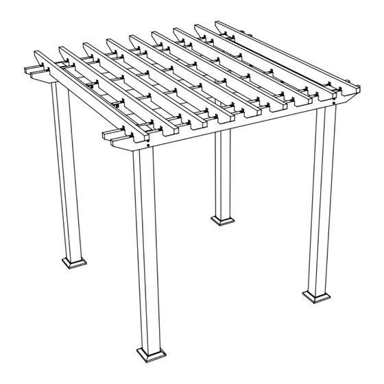
- Page 1 10’x10’ INSTALLATION INSTRUCTIONS WPC PERGOLA Option A Option B...
- Page 2 3048mm/120’’ 2052mm/80.76” 3048mm/120’’ 269mm/10.59” 2454mm/96,6” 2454mm/96,6” Base plate cover...
- Page 3 L1: U-clip X16 L2: M8 60mm screw bolt X16 L3: L-angle clip X105 L4: 4.2X25mm screw X270 L5: Expansion screw X16 L6: M10 treaded rod X12 L7: 3.8X25mm screw X40 Base plate cover X4 Drill...
- Page 4 2501mm/98.4” 2105mm/82.8” Straight line Straight line Straight line Z=3537mm/139.2'' Straight line According to the measurement, please put the steel inner post (A) on the ground. ATTENTION: The ground should be flat. STEP:1 STEP:2 Note: Please drill the holes as attention 0.629 the diagram shown.
- Page 5 Before fixing the posts to the ground, refer to the front page of the guide (option A or option B), using the pre-drilled holes on the end of the posts, choose the orientation of the desired roof structure. STEP:3 Fix the expansion screws (L5) STEP:4 same Put the B over the A.
- Page 6 Post Installation A & B STEP:7 Measure and adjust until the following requirements. STEP:6 Use the wrench to fix the expansion screws (L5) 1.Use the Level to ensure the a side and b side of the posts must be vertical to the ground.Please adjust if necessary.
- Page 7 STEP:9 Put the base plate covers (H) on the WPC posts. Measure again...
- Page 8 STEP:1 Assemble the treaded rod (L6) and the U-Clips (L1) as the diagram shown. 8 pieces 4 pieces STEP:2 Install the cross beams (C) with the treaded rod (L6) and the U-clips (L1). middle bottom Note: Please adjust the distance between the posts according to the holes position on the C.
- Page 9 Note: Keep the screws (L7) parallel to the cross beam (C). Keep Parallel Keep Parallel STEP:3 Please pre-drill the holes for the screws (L7) with Φ4mm(Φ0.2”) and fix the screws (L7). Please do not pre-drill the inner aluminum.
- Page 10 Beam F installation Install the beams 2 (F) to the cross beams (C) with the U-Clips (L1) and the screws bolt (L2). Note :The drain holes must be downwards. Note: Please use the wrench to fix the L2 go through the holes of the F tightly.
- Page 11 Beam G installation Note :The drain holes must be downwards. Keep Parallel Keep Parallel Pre-drill the holes on the beam 2 (F), please do not pre-drill the inner aluminum.Fixing the U-Clips (L1) and screws (L7) with the holes we pre-drill as the diagram shown.
- Page 12 Beam D installation STEP:1 Fix the L-angle clips (L3) and the screws (L4) to the beams (D). Fix the L-angle clips (L3) and the screws (L4) to the beams (D). Put the beams (D) on the cross beams (C), one piece on each side.
- Page 13 STEP:2 Pre-drill the cross beams (C). ATTENTION: Do not pre-drill the inner aluminum. The hole Φ5mm Aluminium Aluminium STEP:3 Measure the distance of the cross beams (C) as the diagram shown which is 222mm/8.74” and mark the points. Fix the screws (L4) on the cross beams (C).
- Page 14 Beam E installation Beam (E) Fix the L-angle clips (L3) and the screws (L4) to the beams (E). There are 6 cuts on each pieces. Please adjust the cuts to fit onto the cross beams (C). E×7 STEP:1 Adjust the distance between the two pieces of the beam 1-2 (E), the distance “P” is 269mm/10.59”...
- Page 15 STEP:2 Pre-dril the points on the WPC beam and do not pre-drill the inner aluminum. The hole Φ5mm Aluminium Aluminium STEP:3 Fix the screws (L4) and measure again the distance as the Page 1 show. Fix the screws (L4) on the cross beams (C).
Need help?
Do you have a question about the WPC PERGOLA and is the answer not in the manual?
Questions and answers