
Summary of Contents for BEP 600-DCSM
- Page 1 600-DCSM DC SYSTEMS MONITOR Installation and Operating Instructions INST-600-DCSM-V1 Page 1...
- Page 2 This page has been deliberately left blank INST-600-DCSM-V1 Page 2...
-
Page 3: Table Of Contents
Table of Contents BASICS Features Specifications Hardware Layout Button Function Power Up Status Page Onscreen Keyboard Saving Dimensions INSTALLATION Plug Information Wiring Diagram CONFIGURATION DC Voltage DC Current Battery Capacity Tank Systems In Operation Mimic Pump Alarms SETTINGS Display Settings Status Pages Inputs System... -
Page 4: Basics
1. Basics Features The 600-DCSM Monitor offers the following features: 2.8” 16 bit TFT LCD colour screen Auto backlighting on key press. Also controlled by external signal 8 programmable inputs for DC Voltage, Tank, Systems In Operation & Pump monitoring ... -
Page 5: Hardware Layout
Hardware Layout Screw Cover Screw Cover Escape button Up button Down button Enter button Socket A Socket B Socket Chapter 1 Basics Page 5... -
Page 6: Button Function
Button Function Escape Button Exits from the page or menu you are currently on and brings up the previous page or menu. Down Button Moves down in page number or down the list on a menu. When inputting text button moves cursor to the left. -
Page 7: Status Page
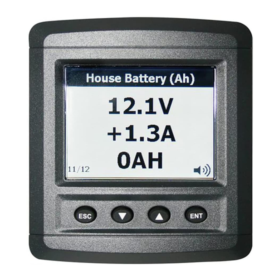
The meter will now load the settings and then boot to the Status Page. Refer to the Settings Chapter on Inputs for more information about Input Types Status Page A Status Page is the first screen that the meter will show after booting. To navigate through the enabled status pages press the ‘Up’... -
Page 8: Saving
Step 1 Press the meters Up or Down button to move the selection box to the character of choice then press the Enter button to accept. Any existing labels will be overwritten by first character input. Tip. To quickly move selection box through the keyboard press and hold the Up or Down buttons. Step 2 Repeat Step 1 until the required label is finished. - Page 9 Selecting ‘yes’ will overwrite the user settings file with these changes, selecting ‘no’ will keep the changes, however the user settings file will not be overwritten and meter will revert back to last save on power up. Note: Refer to the Settings chapter for more information on user settings. Chapter 1 Basics Page 9...
-
Page 10: Dimensions
Dimensions 89.19 [3 1/2"] 20.28 [13/16"] 29.43 [1 3/16"] 8.17 [5/16"] 17.6 [11/16"] Chapter 1 Basics Page 10... -
Page 11: Installation
2. Installation Plug Information Type Positive supply input Negative supply input Remote alarm output Backlight control input DC Current 1 - DC Current 1 + DC Current 2 - DC Current 2 + Input 1 (DC Voltage/Pump/Tank/SOM) Input 2 (DC Voltage/Pump/Tank/SOM) Input 3 (DC Voltage/Pump/Tank/SOM) Input 4 (DC Voltage/Pump/Tank/SOM) Input 5 (DC Voltage/Pump/Tank/SOM) - Page 12 Chapter 2 Installation Page 12...
- Page 13 SOM (Systems In Operation) Chapter 2 Installation Page 13...
- Page 14 TLM (Tank level Monitoring) Chapter 2 Installation Page 14...
-
Page 15: Configuration
3. Configuration DC Voltage Label DC Voltage Value Calibration Voltage Calibration is factory set. If you need to alter the calibration follow the steps below: Go to Main Menu > Setup > Input(s) > ‘Choose Voltage Input’ > Calibration. Step 1 Insert a ground wire into the pin of the input you are configuring. -
Page 16: Dc Current
Gauge Min This is the minimum scale for Gauge View Gauge Max This is the maximum scale for Gauge View DC Current Label DC Current Value Charging Status Calibration Current Calibration is factory set. If you need to alter the calibration follow the steps below: Go to Main Menu >... - Page 17 Load side Battery side Fig. 1 Step 2 Select ‘Zero’. Ensure shunt is wired as Fig.2 below, make sure the zero value is stable and not moving, then select ‘Yes’ to confirm zero. Note: Shorting shunt acceptable for a zero voltage Fig.
-
Page 18: Battery Capacity
Gauge Min This is the minimum scale for Gauge View. Gauge Max This is the maximum scale for Gauge View. Battery Capacity Label Battery Battery Voltage Current Capacity Remaining The true capacity of a battery is dependent on the rate of discharge. The faster the rate of discharge, the less total Ah capacity can be delivered. - Page 19 Example: 8G4D 180A/Hr Battery Discharge 1 = 24 hours @ 7.8 Amps Discharge 2 = 8 hours @ 20.7 Amps n = log T2 - log T1 log A1 - log A2 = log 8 - log 24 log 7.8 - log 20.7 = 0.90 -1.38 0.89 - 1.32 = 0.48...
- Page 20 Step 1 Ensure both Battery Voltage and Current are calibrated. Refer to DC Current & DC Voltage Calibration section. Step 2 Check ‘Voltage Input’ and ‘Current Input’ settings. They should be linked to the same battery you are calibrating the Capacity for. Step 3 Enter the Maximum Capacity for the Battery.
-
Page 21: Tank
Go to Main Menu > Setup > Input(s) > ‘Choose Tank Input’ > Settings Note: Tank inputs are configured for use with 0-5V senders. 10-180Ω and 240-33Ω senders must be used in conjunction with BEP 600-TLM-SIF. Mode: Marking Step 1 Enter the tank volume. -
Page 22: Systems In Operation
Step 4 Add the next increment of fluid calculated in step 2 into the tank. Select ’25.0%’ and then ‘Enter’ to save set point. Repeat the process for 37.5%, 50%, 62.5%, 75%, 87.5% and Full. Mode: Custom Use custom mode if the set point voltage values are already known from a previous tank meter setup. -
Page 23: Mimic
Go to Main Menu > Setup > Input(s) > ‘Choose SOM Input’ > Settings Active State This setting is how the meter decides the Circuit is on, either in Active High or Active Low. High Voltage The volts value for an Active High State. Low Voltage The volts value for an Active Low State. -
Page 24: Pump
Note: All circuit indicator’s are set on there respective SOM page. Refer to SOM Configuration section. Setup Go to Main Menu > Setup > Input(s) > ‘Choose Mimic Page’ > Settings > Image File Select ‘Default List’ to choose between one of the default images. Select ‘New File’... -
Page 25: Alarms
Active State The Active State is set to determine when the pump is on, either in Active High or Active low. When the voltage is equal to or greater than ‘High Voltage’ setting, it is considered Active High. When the voltage is equal to or less than ‘Low Voltage’ setting, it is considered Active Low. High Voltage The volts value for an Active High state. - Page 26 When an alarm is active you will see an Alarm Window for each active alarm and the buzzer/external alarm will sound. The Alarm Window will tell you which input is alarming and what type of alarm it is i.e. Low On or Low Voltage. The label for all alarming circuits will be red also. To remove the Alarm Window from the Status Page you have 2 options: Disable the alarm You will get no further alarms from this input until it is re-enabled.
- Page 27 Global Alarms Use this setting to disable or enable all alarms. Note: This overwrites all enabled alarms so you will not receive any further warnings until global alarms are enabled again. Input Alarm Settings Go to Main Menu > Setup > Input(s) > ‘Choose Input’ > Alarm Enabled Use this setting to disable the alarms for the selected input.
-
Page 28: Settings
4. Settings Display Settings Choose Main Menu > Setup > Display to access Display Settings Backlight Day Level The backlighting level for when meter is set to Day Mode. Set as a percentage between 0-100%. 100% being the brightest. Backlight Night Level The backlighting level for when meter is set to Night Mode. -
Page 29: Inputs
Scroll Mode The scroll mode is how the meter changes from one Status Page to the next. Manual mode requires the user to press the Up or Down button to move through pages. Automatic mode will change between pages at a predetermined hold time (see below). Hold Time The hold time is the time it takes for the meter to change from one Status Page to the next in Automatic Scroll mode. - Page 30 There are 5 types of inputs that are assigned to specific pins (DC Voltage, DC Current, Pump, Tank & SOM). There are also 2 different page views that take data from designated Inputs and display as Text or Graphics (Mimic & Battery). Below is a Table to show the relation between Page Number, Pin Number and Input Type: Page Input Type...
-
Page 31: System
Input Type Display Type DC Voltage Text, Gauge DC Current Text, Gauge Pump Text Tank Text, Gauge, Bar Text Mimic Text, Image Battery Text, Bar Alarm Refer to Alarm Configuration section. Settings The Settings options are specific to the Input Type. Refer to the Configuration section for more detail. -
Page 32: Utilities
To set up a new password select ‘Setup Password’ and then ‘New Password’. The password will need to be entered twice for confirmation. Once this is done the new password will be set up. To disable the password select ‘Setup Password’ and then ‘Disable’. The current password will need to be entered again to disable it. - Page 33 The Save Settings function will save all current changes to the meter settings file. Update Firmware To ensure your meter is using the latest software, please check the BEP Marine website regularly. To find out the current firmware version choose Main Menu > Setup > About.
-
Page 34: Programming Menu Flow Diagram
Programming Menu Flow Diagram Main Menu Page Select Status Page Page Select Input 1 to... Alarm Global Alarms Alarm(s) See Alarm Input 1 to... Display See Input Input Configuration Backlight Day Level Backlight Night Level Backlighting Backlight Setup Timeout Level Backlight Setup Display...
Need help?
Do you have a question about the 600-DCSM and is the answer not in the manual?
Questions and answers