Table of Contents
Advertisement
Advertisement
Table of Contents

Summary of Contents for auris Monarch Platform
- Page 1 MONARCH™ PLATFORM User Manual 300-002547-00 rev7...
- Page 2 300-002547-00 rev7...
- Page 3 Monarch™ Platform User Manual Date of Last Revision: 2018-05-08 300-002547-00 rev7...
- Page 4 This document, the software and products to which this document refers, and any other related materials are the copyrighted and proprietary information of Auris Health, Inc. and may not be used or distributed without written authorization of Auris Health, Inc. No part of this document may be photocopied, reproduced, or translated into another language without written permission from Auris Health, Inc.
- Page 5 Auris’s products and services; or (d) for injury, death, or harm of any nature (whether direct or indirect, and whether or not...
- Page 6 Auris Health, Inc. reserves the right to revise this publication and to make changes in content from time to time without obligation on the part of Auris Health, Inc. to provide notification of such revision or change.
- Page 7 CAUTION: Federal law restricts this device to sale by or on the order of a physician. Safety Precautions and Warnings Safe operation of the Monarch Platform requires careful attention to the serious hazards associated with use of the device and ways to avoid or minimize the hazards, and familiarity with emergency procedures.
- Page 8 Disposal When an Auris product reaches the end of its useful life and your facility desires to remove the device, contact Auris Customer Care at +1.800.434.0032 (toll-free within the United States) or +1.650.264.6000 (Worldwide) to uninstall and appropriately dispose of the components.
- Page 9 Standard Number Standard Title ISO 11607-2:2006 Packaging for terminally sterilized medical devices – Part 2: Validation requirements for forming, sealing and assembly processes ISO 10993-5:2009 Biological evaluation of medical devices -- Part 5: Tests for in vitro cytotoxicity (Biocompatibility) ISO 10993-10:2010 Biological evaluation of medical devices -- Part 10: Tests for irritation and skin sensitization (Biocompatibility) ISO 10993-11:2006...
- Page 10 viii 300-002547-00 rev7...
- Page 11 300-002547-00 rev7...
-
Page 12: Table Of Contents
Contents ............. 1 Monarch Platform Device Overview ................2 System Overview ......................3 Pre-Procedural Planning ..................3 Monarch Cart ......................3 Monarch Tower ..................... 7 Monarch Bronchoscope System ................9 Working Channel Instruments ................10 Accessories ......................10 Classifications ......................11 ... - Page 13 Perform an Unplanned Case ..................38 ......................39 Software Information ....................40 Suggested Bronchoscopy Suite Configuration ............40 Prepare the Bronchoscopy Suite ................41 Prepare the Patient ....................41 Prepare the Monarch Bronchoscope System ............43 Monarch Tower System Setup Guidance ..............44 Monarch Controller ....................
- Page 14 Disassemble and Clean the Monarch Navigation Field Generator ...... 86 Disassemble and Clean Bronchoscope Patient Introducer Mount ...... 86 Clean and Store the Monarch Cart ..............86 Clean the Monarch Tower and Store the Monarch Platform ....... 86 Servicing ........................87 Preventative Maintenance ................... 87 ...
- Page 15 Controller Does Not Appear Functional ............... 98 Field Generator or Patient Introducer Mount Clamps Do Not Tighten ....99 Monarch Platform Will Not Turn On..............99 Tower and Cart Do Not Turn On Simultaneously ..........99 Video (Start Screen) Does Not Appear on Tower and Cart Monitor After System Turns On ......................
- Page 16 300-002547-00 rev7...
- Page 17 CAUTION: Do not modify this equipment. Modification of this equipment may result in injury to users or patients and may void product warranties. Installation of this system is to be performed only by an authorized Auris representative. There are no user serviceable components. Contact Auris Customer Care at +1.800.434.0032 (toll-free within the United States) or +1.650.264.6000 (Worldwide) to...
-
Page 18: Monarch Platform Device Overview
Monarch Platform Device Overview This user manual refers to the Monarch Platform and the associated components used with it. Refer to the following table for a list of products. Official Product Name Shortened Name Monarch™ Platform Monarch™ Pre-Op Planning Application Planning Application Monarch™... -
Page 19: System Overview
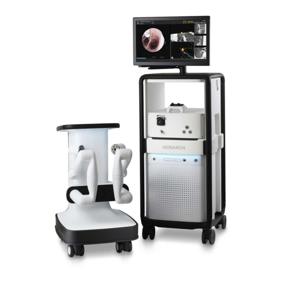
The Monarch Platform enables electro-mechanical articulation and precise control of a flexible endoscope (bronchoscope) under continuous and direct control by a physician operator. The Monarch Platform includes fused navigation that integrates a pre-operative computed tomography scan into an intra-operative interface displaying endoscope tip location relative to the pre-operative scan anatomy. - Page 20 The following image shows the Monarch Cart with the robotic arms in the stow position (left) and load Bronchoscope System position (right): The Monarch Cart is a carrier for the robot arms. It includes two robotic arms which contain rotary pulleys to actuate the drive cables in the Monarch Bronchoscope System.
- Page 21 Item Description Foot pedal Power cable Umbilical port Power button Emergency stop button (E-stop) Cart directional lock switch Cart handle Cart Touchscreen Instrument Device Manipulator (IDM) Robotic arm Vertical lift Immobilization feet (not shown) 300-002547-00 rev7...
- Page 22 Item Description Power button Umbilical port to the Monarch Tower Power cord plug Automated lift controls will raise and lower the height of the robotic arms based on your control. The cart handle allows the cart to be directionally locked for ease of maneuverability.
-
Page 23: Monarch Tower
Software, the Monarch Navigation Application, which displays real time video captured from the Monarch Bronchoscope camera overlaid with information on the status of the Monarch Platform and the Monarch Pre-Op Planning Application. The tower also provides connectivity for the Monarch Bronchoscope camera and lighting, as well as the fluidics system. - Page 24 UPS which provide auxiliary power in the event of system fault. NOTE: The Monarch Platform incorporates an uninterruptible power supply backup. In the event of a power outage, the backup supply provides a five-minute operating window, which allows the operator to safely remove the Monarch Bronchoscope System and shut down the Monarch Platform.
-
Page 25: Monarch Bronchoscope System
The following image shows the Monarch Controller: Monarch Bronchoscope System The Monarch Bronchoscope System is comprised of two collinear and concentric devices, the inner Monarch Bronchoscope and the outer Monarch Bronchoscope Sheath, both of which possess 4-way steering control. This configuration enables the capability of telescoping, which enhances the Monarch Bronchoscope System stability and access capability. -
Page 26: Working Channel Instruments
Working Channel Instruments The following single-use manually controlled Auris instruments compatible with the Monarch Platform are provided sterilized: Aspirating Biopsy Needle, Biopsy Forceps, and Cytology Brush. Refer to individual Instructions for Use included with each working channel instrument for additional information. -
Page 27: Classifications
Disposable Accessories The system features sterilized single-use accessories necessary to perform bronchoscopic procedures. These accessories are: Bronchoscope Patient Introducer: A tube that guides the Bronchoscope System through the Bronchoscope Swivel Adapter and into the endotracheal tube. Bronchoscope Swivel Adapter: Standard bronchoscope accessory that attaches to the endotracheal tube to allow passage of a bronchoscope while maintaining ventilation pressure. -
Page 28: Monarch Platform Labels
The Monarch Platform is classified by the following: Protection against electric shock: Class 1 (grounded equipment). Applied part(s): All Applied Parts of the Monarch System are Type BF Applied Parts. Protection against harmful ingress of water: Rated IPX0 (ordinary equipment, not specially protected). - Page 29 Symbol Name Meaning Emergency Stop This symbol indicates an emergency stop control device. Read instructions prior This symbol is used to alert the user to refer to to use the user manual or other instructions when complete information cannot be provided on the label.
- Page 30 Symbol Name Meaning Single-use only Used to warn the user that the piece of equipment with this label is for single-use only and it must not be used more than once. Use by date This symbol indicates that the device should not be used after the date accompanying the symbol.
-
Page 31: Label Locations
Label Locations The following figures show the system labels and their locations. The Monarch System UDI is located on the tower. Cart 300-002547-00 rev7... -
Page 32: Technical Specifications
Tower Technical Specifications Physical Dimensions, Weight, and Power Requirements NOTE: AC power cord is mains disconnect device. Subsystem Monarch Tower Monarch Cart Height 66.4”/168.7 cm 39.8”/101.1 cm Width 24.7”/62.8 cm 23.9”/60.7 cm Depth 29”/73.6 cm 34”/86.4 cm Weight (maximum) 892 lb/405 kg 785 lb/356.4 kg 300-002547-00 rev7... -
Page 33: Declaration Of Emissions
Operate the system with all covers closed. Operating the system with any cover open may affect EMC performance. The Monarch Platform may be used safely while connected to other devices if the devices and their specifications, installation, and interconnection with the... - Page 34 Table 1. Guidance and Manufacturer’s Declaration – Electromagnetic Emissions – For All ME Equipment and ME Systems Guidance and Manufacturer’s Declaration – Electromagnetic Emissions The ME System is intended for use in the electromagnetic environment specified below. The customer or the user of the ME System should assure that it is used in such an environment. Emissions Test Compliance Electromagnetic Environment - Guidance...
-
Page 35: Declaration Of Immunity
Declaration of Immunity The Monarch Platform is to be used per the specified guidance and only in the electromagnetic environment listed below. Table 2. Guidance and Manufacturer’s Declaration – Electromagnetic Immunity – For All ME EQUIPMENT and ME SYSTEMS Guidance and Manufacturer’s Declaration – Electromagnetic Immunity The ME System is intended for use in the electromagnetic environment specified below. - Page 36 IEC 60601 Test Compliance Electromagnetic Environment – Immunity Test Level Level Guidance <5 % U 5 % U Voltage dips, Mains power quality should be that of short a typical commercial or hospital (>95 % dip in U (>95 % dip in U interruptions and environment.
- Page 37 80 MHz to 2,5 Recommended separation distance �� √�� �� �� √�� 80 MHz to 800 MHz �� �� √�� 800 MHz to 2,5 GHz �� where P is the maximum output power rating of the transmitter in watts (W) according to the transmitter manufacturer and d is the recommended separation distance in...
-
Page 38: Original Documentation
Table 4. Recommended separation distances between portable and mobile RF communications equipment and the ME Equipment or ME System – for ME Equipment and ME Systems that are not Life-supporting Recommended Separation Distances Between Portable and Mobile RF Communications Equipment and the ME System The ME System is intended for use in an electromagnetic environment in which radiated RF disturbances are controlled. - Page 39 Planning a Procedure Prior to starting the procedure, the Monarch Pre-Op Planning Application is available on both the Monarch Pre-Op Planning System and Monarch Tower to create a patient case that contains DICOM and planning data. You can export files to be transferred between the tower and laptop.
-
Page 40: Recommended Ct Scan And Reconstruction Parameters
Recommended CT Scan and Reconstruction Parameters In order to produce CT images suitable for use with the Monarch Pre-Op Planning Application and the Monarch Navigation Application, the following conditions should be met while scanning the patient: Patient position: Supine, immobile, full inspiration breath hold, arms at sides. - Page 41 The following table lists the slice thickness and slice interval for a 50% and 20% overlap: Slice Minimum Slice Interval (mm) Maximum Slice Interval (mm) Thickness (mm) (at 50% Overlap) (at 20% Overlap) 1.25 0.625 0.75 1.00 1.25 1.50 2.00 2.50 NOTE: Overlap % = 100 x (thickness - interval) / thickness.
-
Page 42: Monarch Pre-Op Planning Application User Interface
Monarch Pre-Op Planning Application User Interface When you log on to the Monarch Pre-Op Planning Application, the Patient List appears. Patient List Patient List Menu Item Description Logout Click or tap to log off from the Monarch Pre-Op Planning Application. Settings Click or tap to update password, add users, and administrative settings. - Page 43 General Patient Information The Patient List displays the following general patient information. Item Description Patient ID Displays the patient’s ID. Patient Name Displays the patient’s name. Study Date Displays the date of the study. Selected Patient Information WARNING: Entering data in the wrong patient case can result in planning errors, which may lead to serious injury.
- Page 44 Item Description Patient ID Displays the patient’s ID. Patient Name Displays the patient’s name. Study Date Displays the date of the study. Displays the patient’s sex. Case ID Displays the case ID associated with the selected patient. Date of Birth Displays the patient’s date of birth.
-
Page 45: Planning
Planning Patient Information Item Description Patient ID Displays the patient’s ID. Patient Name Displays the patient’s name. Date of Birth Displays the patient’s date of birth. Hospital Displays the hospital where the procedure is being performed. Tools Item Description Click or tap to add an overlay of an axial CT image on the airway tree in Segmentation view. - Page 46 Item Description Click or tap to change the boundary box and highlighted target anatomy to a sphere. Click or tap to create a virtual “fly-through” video from the trachea to the target along the path. While the video plays, the play icon changes to a stop icon. Click or tap the icon to stop the video.
- Page 47 Item Description A boundary box can be resized in any of the three 3 CT images. To adjust the outer boundaries of the target, drag a sizing handle away from or toward the center until the desired size is reached. The image is adjusted in all three CT images when updates are made in one image.
-
Page 48: Manual Path
Manual Path Manual plans begin at the weighted center of the target and work towards the main airways. The green ball represents the weighted center of the target. The lower-right image viewer is the Segmentation view. Manual Path Menu NOTE: All points are deleted if the manual path does not reach the segmented area. -
Page 49: Before You Can Plan
Touchscreen Item Mouse Action Description Click a point in the Add multiple points to create a manual path. segmentation screen. Delete Deletes a point that you inserted. Close Click Close. Exits the Manual Path screen. Segmentation Review WARNING: Ensure that the segmentation generated from the CT scan accurately identifies the airways. - Page 50 4. Click or tap the patient DICOM and the select Import. The new case automatically loads, and the Planning screen appears. 5. Click or tap a patient from the list and select Open. The Planning screen appears. 6. Double-click or double-tap for a full screen view of any of the image view windows.
-
Page 51: Identify A Target
Identify a Target WARNING: Increased size of nodule selection may lead to path creation to critical anatomy. Confirm that the selected nodule is the intended target. WARNING: Path creation provides supplemental information to navigate to nodule. Failure to exercise clinical judgment to determine appropriate navigation and biopsy plan may result in biopsy of unintended location. - Page 52 in the Segmentation view. To return to the small image viewer, double-click while in full-screen mode. To change the view angle, click (or tap and hold on the Touchscreen) and move the cursor around on the screen. Use the Add icon and click to add points (or right-click with the mouse).
-
Page 53: Export A Patient Case
7. To delete a target: a. Select the target to be deleted. b. Click or tap – next to Targets to delete the target. 8. To delete a path: a. Select the path to be deleted. b. Click or tap – next to Paths to delete the path. 9. -
Page 54: Import A Patient Case
Unapprove a plan to make changes. Perform an Unplanned Case If you want to use the Monarch Platform using only the live camera without navigational assistance, you can perform an Unplanned Case. When you perform an unplanned case, you will only see the Live Bronchoscope view. - Page 55 System Setup The Monarch Tower and Cart provide step-by-step guidance to ensure that the Monarch Bronchoscope System and related components are ready for use. The software prevents you from advancing to the next screen if you have not successfully completed the task.
-
Page 56: Software Information
Software Information Select the About icon on the Tower Touchscreen, Cart Touchscreen, or laptop logon menu to view information about the Monarch Software, including the UDI and copyright. Suggested Bronchoscopy Suite Configuration The following is a suggested configuration of where to place the Cart and Tower in respect to the patient’s left side in the bronchoscopy suite. -
Page 57: Prepare The Bronchoscopy Suite
Prepare the Bronchoscopy Suite 1. Bring the following Monarch single-use items into the procedure room. a. Bronchoscope Fluidics Tubing. b. Working channel instruments (Aspirating Biopsy Needle, etc.). c. Bronchoscope Patient Introducer Kit (includes Bronchoscope Patient Introducer and Bronchoscope Swivel Adapter). d. - Page 58 3. Anesthesiologist or physician will intubate the patient. Once the endotracheal tube is placed, the tube can be cut if desired. Use of this device is restricted to endotracheal tubes 7.5mm and greater. The patient should not be moved when the Monarch Bronchoscope System or related equipment is inserted into patient airways.
-
Page 59: Prepare The Monarch Bronchoscope System
Prepare the Monarch Bronchoscope System WARNING: The bronchoscope and sheath must be lubricated prior to insertion. Failure to lubricate the bronchoscope and sheath may cause buckling and poor scope driving responsiveness. 1. Open the Monarch Bronchoscope System package and remove the pouched tray. -
Page 60: Monarch Tower System Setup Guidance
6. Remove the Monarch Bronchoscope Sheath from its packaging tube and lubricate the shaft. NOTE: Use only silicone-based lubricants such as Silkospray Universal Silicone Spray. 7. Open the Bronchoscope Sheath Valve package. 8. Place the Bronchoscope Sheath Valve over the Luer fitting on the back of the Monarch Bronchoscope Sheath. -
Page 61: Fluidics System
Fluidics System 1. Unpack the Bronchoscope Fluidics Tubing from its sterile packaging. Connect the end of the tubing with a Luer fitting valve to the Monarch Bronchoscope System handle Luer fitting. 2. Attach the tubing (blue stripe) to the irrigation pump. Note the direction of the arrow, which defines pumping direction. -
Page 62: Camera
Camera 1. Plug in the Bronchoscope camera cable to the tower. 2. Verify that the camera is live. 3. Press Navigation to continue. Navigation 1. Plug in Monarch Navigation Field Generator to the tower while leaving it in tower cabinet. 2. - Page 63 13. Press Start Procedure to continue. NOTE: Ensure fluoroscopy system has a minimum clearance distance of 70 cm vertically and laterally from the Field Generator. To do so may affect the measurement volume, contributing to inaccurate transformations. NOTE: In larger patients, it may be difficult for all three sensors to turn green. In this case, the sensor furthest away from the Field Generator should be the one designated as yellow or orange.
-
Page 64: Monarch Cart System Setup Guidance
Monarch Cart System Setup Guidance NOTE: Ensure there is appropriate clearance between the Monarch Cart and the patient and staff. Unstow Cart 1. Press Start to confirm that the Monarch Cart is ready to set up to the patient. 2. Roll the Cart to the correct side of the patient with approximately 36” between the cart and the bed. - Page 65 4. Move the Cart to align the robot arms within approximately 2 inches of the Patient Introducer. 5. Immobilize the Cart by pumping the foot pedal until the cart is lifted and the green indicator light appears on the screen. You are unable to use the software until the cart is immobilized.
- Page 66 7. Make sure the IDM touches the alignment feature (as shown in the following image). 8. Press Set. 300-002547-00 rev7...
-
Page 67: Load The Monarch Bronchoscope System
Load the Monarch Bronchoscope System WARNING: Do not reuse the Monarch Bronchoscope System, Bronchoscope Fluidics Tubing, Bronchoscope Patient Introducer, or working channel instruments. These devices are single-use only. WARNING: Do not use the Monarch Bronchoscope System, Bronchoscope Fluidics Tubing, Bronchoscope Patient Introducer, and working channel instruments if sterile barrier has been damaged. - Page 68 3. Assemble the Monarch Bronchoscope and Monarch Bronchoscope Sheath by inserting the bronchoscope through the Bronchoscope Sheath valve and through the sheath. 4. Insert the tip of the Monarch Bronchoscope System into the Patient Introducer up to the end of the bronchoscope swivel adapter. 5.
- Page 69 Performing a Procedure Overview ........................54 Functional Descriptions of Monarch Components ............. 54 Biopsy Instruments ....................57 Monarch Navigation Application User Interface ............58 Procedural Steps or Actions ..................78 Perform Biopsy ......................80 Post-procedure ......................81 300-002547-00 rev7...
-
Page 70: Overview
Overview Each procedure consists of tasks and each task has one or more steps. In performing a procedure, you will typically perform the following steps: 1. Drive the Monarch Bronchoscope System forward to the main carina. 2. Initialize navigation. 3. Drive the Monarch Bronchoscope System to nodule. 4. -
Page 71: Monarch Controller
Item Description Camera Lights (x2) Working channel (2.1mm) Monarch Platform Device Compatibility Working channel instruments are restricted to those that are compatible with a working channel diameter of 2.1mm. Device Sterility Contents supplied sterile using an ethylene oxide (EO) process. - Page 72 Item Description Insert/Retract joystick Menu button Quick Action button Pause/Start button Articulate (outer) and Relax (inner) joystick Light, Program, and Snapshot buttons Directional pad 300-002547-00 rev7...
-
Page 73: Working Channel Instruments
Item Description Toggle between Monarch Bronchoscope and Monarch Bronchoscope Sheath. Irrigation button Aspiration button WARNING: Always secure the endoscopic controller. When in the enabled state, dropping or other unintended joystick motion may lead to accidental commanded motion which may cause patient injury, such as pneumothorax, hemorrhage or endoluminal irritation. -
Page 74: Monarch Navigation Application User Interface
Monarch Navigation Application User Interface The Monarch Platform provides access to several custom views that combine the live Monarch Bronchoscope, CT data, and virtual reconstructions of the airway segmentation. These views can be mixed and matched based on physician preference and rearranged during the procedure as needed. - Page 75 300-002547-00 rev7...
-
Page 76: Top Navigation Bar
Top Navigation Bar Item Description Menu icon High Beam icon appears when the Light button is pressed. The feature increases light emission from the tip. Irrigation indicator: Estimated total volume delivered from the pump is displayed. Text turns blue when irrigation is active. Aspiration icon: Appears when aspiration is active. -
Page 77: Scrolling Area
This larger window is called the Primary Area. The increased size allows more information to be shown, in the form of more detailed graphics. When the Live Bronchoscope view is promoted to the Primary Area, additional data not available in the smaller viewing window appears. See Live Bronchoscope (page 66) for examples of how the Primary Area can show additional information. -
Page 78: Ct Area
CT Area The right column offers a collection of supplementary CT views. The CT Area does not scroll and views cannot be promoted from the CT Area to Primary Area. Instead, the views can be selected for zoom to show more detail. When selected, an alternative view window configuration appears with enlarged CT slices as shown below. -
Page 79: Full Screen Mode
This view was designed to support physicians who use the Axial, Sagittal, and Coronal CT views during the procedure. Selecting a CT window automatically dismisses the view. Full Screen Mode Live Bronchoscope – Full Screen Mode When the Live Bronchoscope view is the Primary Area, selecting the Primary Area enlarges it to a Full Screen Mode. - Page 80 Select the menu item using the Monarch Controller or press the corresponding item on the screen. Back to Navigation Press Back to Navigation to return to the Navigation tab. Select Target Press Select Target to select a target to navigate to. Camera Parameters Press Camera Parameters to adjust the camera roll.
-
Page 81: Navigation Views
Navigation Views The Monarch Navigation Application integrates a pre-procedure-computed tomography scan into a peri-procedure interface displaying endoscope tip location relative to the pre-procedure scan anatomy. The navigational information displays the Monarch Bronchoscope tip location relative to the CT scan. The application’s interface includes a virtual representation of the lung with scope tip location. - Page 82 Live Bronchoscope The Primary Area of the Live Bronchoscope shows more detailed information than when located in the Scrolling Area. The core of the Monarch Navigation Application is the Live Bronchoscope view which provides vision in both the central airways and the periphery. This camera view is always displayed in either Full Screen Mode, Primary Area, or Scrolling Area positions.
- Page 83 Insertion depth is at the bottom of the screen. The gray bar (which turns blue when the Sheath is selected) indicates the sheath insertion. The green bar indicates the insertion of the scope relative to the sheath. The green outline indicates the remaining stroke length of the scope.
- Page 84 Item Description Magnitude of Sheath articulation Maximum insertion that the Bronchoscope can reach Maximum insertion that the Sheath can reach Represents the relative insertion of the Bronchoscope (green) into the Sheath (white) Relative insertion values for the Bronchoscope and Sheath 300-002547-00 rev7...
- Page 85 Virtual Bronchoscope The Virtual Bronchoscope view shows the scope position and orientation from inside the airways, generally mirroring the view of the live camera. The Virtual Bronchoscope view is designed to help visualize the next turn. It is a real-time virtual representation of the pathway that updates relatively with camera pitch, yaw, roll, and position along the planned path.
- Page 86 3D Map View Example of a planned pathway relative to the airway tree: The white ball represents the scope position and the yellow ball represents the target. 3D Map view is a virtual representation of the patient’s airway tree with the location of the planned pathways and targets superimposed.
- Page 87 Local View This CT-based view combines a virtual representation of the nodule with an oblique slice of the CT volume based on the scope orientation. For targeting, the CT plane intersects the virtual nodule, allowing you to determine when the target is in plane. The CT forms a virtual “water line,” showing the point of intersection.
- Page 88 Targeting Views Orbit View The Orbit view for targeting shows the biopsy position from the nodule’s perspective. The view “orbits” around the target allowing you to view the alignment from different angles. This view always focuses on the nodule and attempts to adaptively keep the scope tip in frame during the approach by revolving around the nodule to keep both it and the scope in view.
- Page 89 Tip View The Tip view is a targeting view that displays the biopsy position from the tip of the scope’s perspective to aid in working channel alignment. The view is comprised of a crosshair, which is aligned with the scope’s working channel, and the nodule, which consists of a yellow grid.
- Page 90 Axial, Sagittal, and Coronal CTs The planar CT views are sized to fit the sidebar windows and zoom window. The Monarch Navigation Application adaptively scrolls and pans the CT based on scope location, keeping the scope always in frame. The CT images are sized to fit the width of the window, scrolling only vertically. When zoomed using the quick action button, the CT images scroll horizontally.
-
Page 91: Configuring View Screens
Axial Configuring View Screens The Navigation views can be re-arranged during the procedure as needed. Using the directional pad on the Monarch Controller, scroll through the Scrolling Area to select your views. The following image is an overview of the view arrangement structure. - Page 92 Use the Scrolling Area to select among different views. Once you select a view, it’s promoted to Primary Area. If you select one of the CT views, the screen transitions to a CT-centric view as described above. 300-002547-00 rev7...
-
Page 93: Quick Action Button
Quick Action Button If you have the Monarch Controller highlighting any of these screens, the quick action button will give you the functions as illustrated below. The Quick Action button activates on demand features that are unique for each view. Item Description 3D Map View... -
Page 94: Procedural Steps Or Actions
Item Description Virtual Bronchoscope View Press: Elevates virtual camera. Hold: Moves the camera along the paths in the order of rank. Orbit View Press: Transitions from Orbit View to Tip View. Hold: Rotates the view around the nodule. CT Views ... -
Page 95: Navigation Initialization
3. Press the Insert/Retract joystick to activate control of the Monarch Bronchoscope System. 4. Insert the Monarch Bronchoscope System through the bronchial adapter and endotracheal tube until you can visualize the main carina. You may need to articulate the scope with the controller to avoid impact with the endotracheal tube upon insertion. -
Page 96: Perform Biopsy
Perform Biopsy WARNING: Ensure fluoroscopy system is operating properly and does not interfere with the Monarch Platform before patient use. NOTE: Do not irrigate with working instruments in the working channel. This can cause pressure build up in the irrigation tubing. -
Page 97: Post-Procedure
Administer Saline or Another Agent Through the Working Channel If you want to administer cold saline or any other agent through the working channel with a syringe, you must disconnect the valve on the backend of the Monarch Bronchoscope and access the working channel with a syringe. Post-procedure When the procedure is complete, use the following guidelines when you retract the Monarch Bronchoscope System. - Page 98 300-002547-00 rev7...
- Page 99 Remove and Clean Equipment ................. 84 Servicing ........................87 CAUTION: Clean and disinfect the Monarch Platform by wiping components with a moist disinfecting cloth. The bedside components should be cleaned and disinfected before each case. All other components should be cleaned and disinfected at least monthly. The...
-
Page 100: Prepare The Patient For Discharge
System If necessary (e.g. product complaint investigation), the Monarch Bronchoscope System may be returned to Auris per the following instructions. Otherwise, all single-use devices, including the Bronchoscope and Bronchoscopic Sheath, should be disposed of according to applicable national and local laws and guidelines. -
Page 101: Clean Monarch Navigation Patient Sensors
2. Immerse distal tip of the Monarch Bronchoscope into the pre-cleaning solution and aspirate enough pre-cleaning solution to remove gross contaminants, as you would for standard endoscopes. 3. Aspirate Monarch Bronchoscope in air until dry. 4. Remove the Monarch Bronchoscope Sheath Valve and attach the vacuum source tubing to the back of the Monarch Bronchoscope Sheath. -
Page 102: Disassemble And Clean The Monarch Navigation Field Generator
4. Press STOW on the bottom navigation bar to return the robot arms in the stow position. Clean the Monarch Tower and Store the Monarch Platform 1. Click Stop Procedure. 2. Click Shutdown to turn off the Tower and Cart. -
Page 103: Servicing
Configuration Video Display The Monarch Platform allows for the use of an external monitor to duplicate the Monarch Platform Tower video on an external display. The external monitor may be connected to the Monarch Platform using an SDI or DVI cable connected at the rear panel of the Tower. - Page 104 Parts Replacement The Monarch Platform does not have any user-serviceable parts with the exception of the following system accessories: Monarch Controller. Navigation Patient Sensors. Bronchoscope Patient Introducer Mount. Field Generator Mount. All replacement parts must be provided by Auris Health, Inc. Contact Auris Customer Care for assistance.
- Page 105 Replacement of the Field Generator Mount 1. Ensure that the Monarch Platform is not in a procedure. 2. Remove the Monarch Navigation Field Generator from the Monarch Navigation Field Generator Mount, if installed on the bed rail. 3. Loosen the clamp securing the Monarch Navigation Field Generator Mount to the bed rail.
- Page 106 300-002547-00 rev7...
- Page 107 User and System Administration User Administration ....................92 System Security ......................95 Networking ........................ 95 300-002547-00 rev7...
-
Page 108: User Administration
The site administrator can create and remove all user accounts and reset a user’s password if lost or forgotten. If a site administrator loses the Admin password, contact Auris Customer Care for password reset or recovery. -
Page 109: Change User Password
REAL NAME AURIS USER ID: the user ID provided by Auris Health, Inc. PASSWORD: a password should have at least 12 characters and contain at least one uppercase letter, one lowercase letter, one number, and one special character/symbol. -
Page 110: Disable Existing User
4. Enter the following information: ADMIN PASSWORD. NEW PASSWORD: a password should have at least 12 characters and contain at least one uppercase letter, one lowercase letter, one number, and one special character/symbol. CONFIRM PASSWORD. 5. To save your changes, select OK. If You Have Security Access to Your Account Only 1. -
Page 111: System Security
The Monarch Platform has the ability to send case information to the Auris data lake. The Auris system de-identifies all PHI from the case data before it is sent to the Auris data lake. Additionally, the connection that is utilized to send the information to the Auris data lake follows a well-architected framework and is communicated via 256-bit encrypted SSL. - Page 112 300-002547-00 rev7...
- Page 113 Troubleshooting Fault Messages and Troubleshooting ............... 98 300-002547-00 rev7...
-
Page 114: Fault Messages And Troubleshooting
Fault Messages and Troubleshooting If any fault messages are unable to be cleared, remove the Bronchoscope System and reboot the system. When rebooting the system, the user must realign the cart to the patient introducer via the setup steps described previously. If the user removes the bronchoscope while the robot arms are positioned for scope insertion, the robot cart will need to be moved so that the scopes can be attached to the robot arms outside of the patient. -
Page 115: Field Generator Or Patient Introducer Mount Clamps Do Not Tighten
2. Inspect the clamp for fluid residue or debris blocking the clamp. Do not disassemble the clamp to inspect. 3. Exercise the clamp by loosening and tightening the knobs. 4. If the knobs cannot be tightened, contact Auris Customer Care for a replacement mount. Monarch Platform Will Not Turn On 1. -
Page 116: Video (Start Screen) Does Not Appear On Tower And Cart Monitor After System Turns On
System. 4. Disconnect the Bronchoscope System from the robotic arms. 5. Reboot the system. 6. If tower and cart video are not present after system reboot, contact Auris Customer Care for support. Navigation Patient Sensors Not Detected During Setup 1. Confirm that sensors are placed on the patient within the Field Generator’s field of view. -
Page 117: Ct Scan Or Pre-Planned Case Cannot Be Uploaded To Tower
4. Move the cable to the opposite connector on the Tower. 5. If problem persists, contact Auris Customer Care for support. CT Scan or Pre-Planned Case Cannot be Uploaded to Tower 1. Reseat disc in DVD player or Monarch USB drive. - Page 118 300-002547-00 rev7...
-
Page 119: Errors And Messages
Errors and Messages System Messages ....................104 300-002547-00 rev7... -
Page 120: System Messages
System Messages The Monarch Platform software constantly monitors system status and reports any error conditions that may trigger a notification. The tables in this appendix include errors, messages, and recommended actions for the Monarch Platform. Table 1 Description Message Config server error A system error has occurred and all robotic functions have been disabled. - Page 121 Message Nav Error A system error has occurred and all robotic functions have been disabled. Press OK to continue. If problem persists, contact Auris support. Nav Error A system error has occurred and all robotic functions have been disabled. Press OK to continue.
- Page 122 Message System Error A system error has occurred and all robotic functions have been disabled. Press OK to continue. If problem persists, contact Auris support. The Cart is disconnected from A system error has occurred. All robotic functions the Tower. Please make sure have been disabled.
- Page 123 Description Message Bronchoscope retraction limit has been reached. Sheath insertion limit has been reached its limit. Sheath retraction limit has been reached. Sheath insertion limit has been reached. Bronchoscope System loading The Bronchoscope System failed to load error properly. Unload and reload the device. Tensioning error The Bronchoscope System failed to load properly.
- Page 124 Description Message Invalid command A system error has occurred. All robotic functions have been disabled. To resolve, unload then reload the Bronchoscope System and click OK to acknowledge the fault. Then, re-initialize navigation at the main carina. Robot joint limit desired A system error has occurred.
- Page 125 A system error has occurred. All robotic functions have been disabled. Unload the Bronchoscope System and reboot the system. If problem persists, contact Auris support. IDM Fault A system error has occurred. All robotic functions have been disabled. To resolve, unload then reload the Bronchoscope System and click OK to acknowledge the fault.
- Page 126 Message Robot IDM power up A system error has occurred and all robotic functions have been disabled. Press OK to continue. If problem persists, contact Auris support. IDM Velocity A system error has occurred. All robotic functions have been disabled. To resolve, unload then reload the Bronchoscope System and click OK to acknowledge the fault.
- Page 127 A system error has occurred. All robotic functions have been disabled. Unload the Bronchoscope System and reboot the system. If problem persists, contact Auris support. Robot control loop disabled A system error has occurred. All robotic functions have been disabled. To resolve, unload then reload the Bronchoscope System and click OK to acknowledge the fault.
- Page 128 A system error has occurred. All robotic functions have been disabled. Unload the Bronchoscope System and reboot the system. If problem persists, contact Auris support. Cart not properly immobilized A system error has occurred. All robotic functions have been disabled. To resolve, unload then reload the Bronchoscope System and click OK to acknowledge the fault.
- Page 129 Message A system error has occurred. All robotic functions have been disabled. Unload the Bronchoscope System and reboot the system. If problem persists, contact Auris support. Camera frame rate issue detected. Check camera visibility. Camera frame rate issue detected. Check camera visibility.
- Page 130 A system error has occurred. All robotic functions have been disabled. Unload the Bronchoscope System and reboot the system. If problem persists, contact Auris support. PDU Initialization Error A system error has occurred. All robotic functions have been disabled. To resolve, unload then reload the Bronchoscope System and click OK to acknowledge the fault.
- Page 131 Message Fluidics error A system error has occurred and all robotic functions have been disabled. Press OK to continue. If problem persists, contact Auris support. Fluidics Initialization Error A system error has occurred. All robotic functions have been disabled. To resolve, unload then reload the Bronchoscope System and click OK to acknowledge the fault.
- Page 132 Description Message Pendant Software Fault 1003 A system error has occurred. All robotic functions have been disabled. To resolve, unload then Pendant control software reload the Bronchoscope System and click OK to fault acknowledge the fault. Then, re-initialize navigation at the main carina.
- Page 133 Description Message 1200 Nav scope EM quality Poor quality navigation field generator data detected. Navigation accuracy may be compromised. Press OK to continue. 1201 Poor quality image detected. Navigation may be compromised. 1202 Poor quality EM data detected. Navigation may be compromised.
- Page 134 A system error has occurred. All robotic functions Mismatch have been disabled. Unload the Bronchoscope System and reboot the system. If problem persists, contact Auris support. 1401 EtherCAT Missing Frame(s) A system error has occurred. All robotic functions Over Max Limit have been disabled.
- Page 135 Auris support. 2005 System Error A system error has occurred and all robotic functions have been disabled. Press OK to continue. If problem persists, contact Auris support. 2007 Invalid SW Revision A system error has occurred. All robotic functions have been disabled.
- Page 136 A system error has occurred. All robotic functions have been disabled. Unload the Bronchoscope System and reboot the system. If problem persists, contact Auris support. 2010 A system error has occurred. All robotic functions have been disabled. Unload the Bronchoscope System and reboot the system.
- Page 137 DofLimit A system error has occurred. All robotic functions have been disabled. Unload the Bronchoscope System and reboot the system. If problem persists, contact Auris support. 2020 IterationLimit A system error has occurred. All robotic functions have been disabled. Unload the Bronchoscope System and reboot the system.
- Page 138 Couldn't find \"%1\" System message Directory \"%1\" does not exist. Failed to import CT dataset. Re-insert the disk and try again. If problem persists, contact Auris support. Failed to segment CT data. Retry segmentation. If problem persists, contact Auris support.
Need help?
Do you have a question about the Monarch Platform and is the answer not in the manual?
Questions and answers