Table of Contents
Advertisement
Publication 350-01001-00, 01/19/2016
Instruction Manual
I n s t a l l a t i o n • O p e r a t i o n • M a i n t e n a n c e
Standard AC generator
Single or two-bearing
Drive-end air discharge
Please read this manual and all included manuals in its entirety
before unpacking, installing, and operating your generator. If your
manual came on a CD, read all the fi les included on the CD.
Kato EngineeringP.O. Box 8447 Mankato, MN USA 56002-8447Tel: 507-625-4011
KatoEngineering@emerson.com www.kato-eng.com
Copyright © 2012 Kato Engineering, Inc. All rights reserved
Fax: 507-345-2798Email:
Page 1
Copyright © 2015 Kato Engineering, Inc. All rights reserved
Advertisement
Table of Contents

Summary of Contents for Kato Engineering Standard AC Generator
- Page 1 If your manual came on a CD, read all the fi les included on the CD. Kato EngineeringP.O. Box 8447 Mankato, MN USA 56002-8447Tel: 507-625-4011 KatoEngineering@emerson.com www.kato-eng.com Copyright © 2012 Kato Engineering, Inc. All rights reserved Fax: 507-345-2798Email:...
-
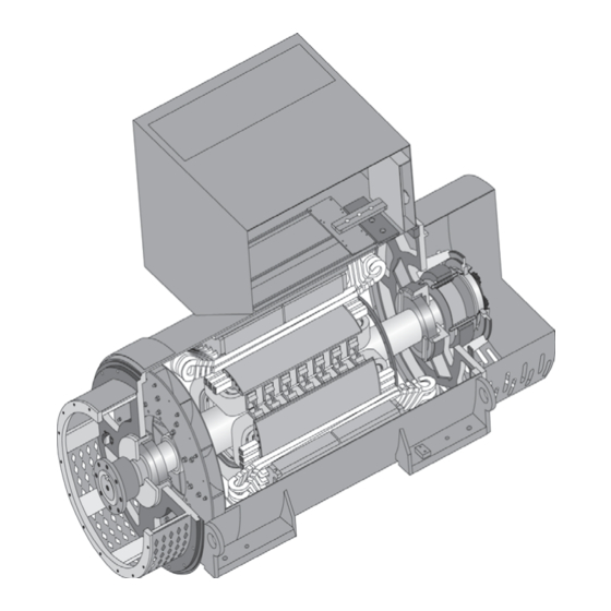
Page 2: Table Of Contents
The image on the front cover is representa- Continuous operation............27 tive only. Several variations are available Idling................. 27 within the range of generators covered Parallel operation.............. 27 within this manual. Copyright © 2012 Kato Engineering, Inc. All rights reserved Page 2... - Page 3 Overall assembly........... 43 Exciter armature and PMG installation....43 Storage................45 Torque chart..........46-47 Troubleshooting Guide........48 Main part location............. 51 List of equipment required for installation and maintenance............. 52 Copyright © 2012 Kato Engineering, Inc. All rights reserved Page 3...
-
Page 4: Introduction
Introduction Foreword This manual contains instructions for installing, operating and maintaining Kato Engineering AC brushless revolving fi eld generators. These generators are manufactured in many sizes and ratings and with WARNING: Shock hazard - Do not service the generator or other electrical various options. -
Page 5: Construction And Operating Principles
Unauthorized lubricants may result in a fi ll and drain ports for easy lubrication. Sleeve bearings are optional bearing failure. on some designs. A supplementary instruction will be included in Copyright © 2012 Kato Engineering, Inc. All rights reserved Page 5... -
Page 6: Connection Boxes
The DC voltage and current levels of the exciter fi eld signal from the voltage regulator varies depending upon the generator output voltage and the loading of the output lines (see Figure Copyright © 2012 Kato Engineering, Inc. All rights reserved Page 6... -
Page 7: Optional Pmg System
fi eld (see Figure 1). Other options Other options include, but are not limited to, space heaters, fi lters, and temperature sensing devices. Copyright © 2012 Kato Engineering, Inc. All rights reserved Page 7... -
Page 8: Installation
Always take extreme care when moving the damage and immediately notify the transportation company claims offi ce generator. Be careful to not strike objects or and Kato Engineering. Be sure to give complete and accurate details personnel. when reporting damage. -
Page 9: Assemble To Prime Mover, Alignment
WARNING: Do not pry on the Figure 2: Flywheel housing check generator fan blades. The blades can weaken, which could result in serious injury or death from fl ying debris. Copyright © 2012 Kato Engineering, Inc. All rights reserved Page 9... - Page 10 Compensation for engine Dial indicator pointer thermal growth must be taken into for radial runout account on this measurement. Shaft Dial indicator pointer for face runou Figure 3: Flywheel check Copyright © 2012 Kato Engineering, Inc. All rights reserved Page 10...
- Page 11 0.003 inch. Adapter Shaft Dial indicator pointer for face runout Dial indicator pointer for radial runout Figure 5: Generator coupling check Copyright © 2012 Kato Engineering, Inc. All rights reserved Page 11...
- Page 12 Mount a dial indicator on the generator shaft or half coupling to the fl ywheel radial surface for parallel alignment as shown in Figure 7. Copyright © 2012 Kato Engineering, Inc. All rights reserved Page 12...
- Page 13 0.005 inch per inch of generator coupling diameter and parallel (radial) total indicated runout does not exceed 0.005” TIR. Torque the fasteners to the value shown in Table 3. Copyright © 2012 Kato Engineering, Inc. All rights reserved Page 13...
-
Page 14: Two-Bearing Alignment
.020”, or .508mm. This will allow for the thermal growth of the shaft. If the generator has “fl oating bearings”, align the face of the outer seat with the groove in the shaft (electrical center). Copyright © 2012 Kato Engineering, Inc. All rights reserved Page 14... - Page 15 Use a straight edge and a thickness gauge for rough alignment as shown in Figure 10. Check for angular and parallel alignment as follows: Straight edge Thickness gauge Figure 10: Rough alignment Copyright © 2012 Kato Engineering, Inc. All rights reserved Page 15...
- Page 16 Tighten the mounting bolts, and recheck alignment. Copyright © 2012 Kato Engineering, Inc. All rights reserved Page 16...
- Page 17 Dial indicator Figure 12: Parallel alignment Copyright © 2012 Kato Engineering, Inc. All rights reserved Page 17...
-
Page 18: Single-Bearing Alignment
fl ywheel bore diameter. Also check to make sure the hole centers match (dimension W of Figure 14 and dimension C of Figure 15). Copyright © 2012 Kato Engineering, Inc. All rights reserved Page 18... - Page 19 If Y is more than G, remove spacers between the drive discs and generator hub. Adaptor Drive plates Shaft Bolt holes Figure 14: Single bearing generator drive plate and adaptor Copyright © 2012 Kato Engineering, Inc. All rights reserved Page 19...
- Page 20 Tighten the fan hub clamping bolt and the set screws. Install the fan bolts and torque them according to Table 3. Copyright © 2012 Kato Engineering, Inc. All rights reserved Page 20...
- Page 21 fl ow through the Set screw Keyway exhaust screen. Bolt holes Alignment mark on drive hub Fan hub bolt Fan hub Figure 17: Moving sheet metal fans Copyright © 2012 Kato Engineering, Inc. All rights reserved Page 21...
- Page 22 Mount the brushless exciter armature assembly to the generator shaft (as described in the assembly procedures below). Adapter Dial indicator pointer Shaft Drive plates Drive hub Figure 18 Runout check Copyright © 2012 Kato Engineering, Inc. All rights reserved Page 22...
-
Page 23: Foot Defl Ection
Disconnect power to the space The thermostat should be set above the dewpoint. Refer to the electrical heaters before removing the generator diagrams for the space heater characteristics. covers. Copyright © 2012 Kato Engineering, Inc. All rights reserved Page 23... -
Page 24: Inspection Before Startup
Fuses need to be sized using the lowest possible current rating above the full-load current rating (115% of rated current is commonly recommended). Remove tools and other items from the vicinity of the generator. Copyright © 2012 Kato Engineering, Inc. All rights reserved Page 24... -
Page 25: Operation
4. Check for vibration levels at no load and rated load. A slight increase is normal. As the load is maintained for 2-3 hours, the vibration levels will gradually increase and reach a fi nal level. Copyright © 2012 Kato Engineering, Inc. All rights reserved Page 25... -
Page 26: Restoring Residual Magnetism/Fi Eld Fl Ashing
Figure 19. 12 or 24 V battery 3 amp or Voltage larger diode regulator Figure 19: Field fl ashing setup with the fi eld wires connected to the regulator Copyright © 2012 Kato Engineering, Inc. All rights reserved Page 26... -
Page 27: Continuous Operation
Where the generator set does not have any of the above options, remove the wires from the voltage regulator input power terminals when the engine is running at less than rated speed. Copyright © 2012 Kato Engineering, Inc. All rights reserved Page 27... -
Page 28: Parallel Operation
fl uctuate from bright to dark at the rate of one cycle every 2 to 3 seconds. When the generator is in phase (the lights will be dark), close the circuit breaker. Immediately after closing the breaker, measure Copyright © 2012 Kato Engineering, Inc. All rights reserved Page 28... - Page 29 Max. current in any phase (% of rated) Figure 20: Guide to allowable phase unbalance System bus Load Synchronizing switch lamps Load lines from the incoming generator Figure 21: Synchronizing paralleled generators with test lamps Copyright © 2012 Kato Engineering, Inc. All rights reserved Page 29...
-
Page 30: Maintenance
Clean the inside of the outlet box, air screens, bearing housings, and air baffl es with compressed air and electrical solvent if needed. Copyright © 2012 Kato Engineering, Inc. All rights reserved Page 30... - Page 31 Inspect the rotor shaft bearing journals for wear or scoring. With generators that have ball or roller bearings, replace the bearings. With generators that have sleeve bearings, replace the bearing liners and oil seals. Copyright © 2012 Kato Engineering, Inc. All rights reserved Page 31...
-
Page 32: Maintenance Procedures
2) support insulation, which includes blocks and slot wedges and are usually made from compressed laminates of fi brous materials, polyester, or similar felt pads impregnated with various types of bonding agents. Check for the following: Copyright © 2012 Kato Engineering, Inc. All rights reserved Page 32... -
Page 33: Cleaning
fl ooding or salt contamination. Copyright © 2012 Kato Engineering, Inc. All rights reserved Page 33... - Page 34 (ºC) Refer to the following electrical measurement procedures for testing 0.23 detail. Contact Kato Engineering or refer to IEEE Standard. 432-1992 0.37 when more extensive insulation tests are required When checking insulation resistance with a megger, fi rst verify the ground path.
-
Page 35: Insulation Resistance Tests At Low Voltage
50 megohms. (See Table 5). 4. Ground the leads to the frame after the 1-minute megger test. This will allow the voltage build up to be properly discharged. Copyright © 2012 Kato Engineering, Inc. All rights reserved Page 35... -
Page 36: Dry Out Procedures
Sleeve bearings: Lubricate the bearings in accordance with the lubricating instructions attached to the generator and the bearing lubrication instructions, which are provided in the manual package as supplementary material. Copyright © 2012 Kato Engineering, Inc. All rights reserved Page 36... -
Page 37: Rectifi Er Tests
A low resistance in both directions indicates a short. A high resistance in both directions indicates an open rectifi er. Cathode Ohmmeter Anode Reverse Standard diode diode Figure 23: Testing the rotating rectifi er with an ohmmeter Copyright © 2012 Kato Engineering, Inc. All rights reserved Page 37... - Page 38 Following replacement, make sure that the revolving fi eld, exciter armature, and rotating diode leads are properly secured. Copyright © 2012 Kato Engineering, Inc. All rights reserved Page 38...
-
Page 39: Disassembly
NOTICE: Make sure the rotor does not rest on the stator during the stages of movement. Make sure the rotor does not hit the stator. Copyright © 2012 Kato Engineering, Inc. All rights reserved Page 39... -
Page 40: Exciter Armature And Pmg Removal
5. Slowly pull the armature assembly off of the generator shaft. If the exciter can not be pulled off by hand, use a hydraulic jack as shown in Figure 27. 6. Remove the key from the keyway in the generator shaft. Copyright © 2012 Kato Engineering, Inc. All rights reserved Page 40... - Page 41 Bolt holes Shoulder Keyway Plate Figure 27: Pulling the armature assembly Hydraulic jack Threaded rod Exciter sleeve Locknut Figure 28: PMG rotor with locking nut Lock washer and tab Copyright © 2012 Kato Engineering, Inc. All rights reserved Page 41...
-
Page 42: Bearing Removal
(see Figure 29). Cap to protect shaft end Puller against bearing Outer ring Inner ring Figure 29: Bearing removal Copyright © 2012 Kato Engineering, Inc. All rights reserved Page 42... -
Page 43: Assembly
Use a fi ber or rubber mallet. If installation is still a problem, use a heat gun to expand the exciter sleeve. Copyright © 2012 Kato Engineering, Inc. All rights reserved Page 43... - Page 44 fl ying debris Exciter armature Minimum air gap diameter (in.) (in.) 5 3/4 0.014 9 7/8 0.014 12 1/2 0.018 16 1/4 0.035 Table 5: Exciter air gap Copyright © 2012 Kato Engineering, Inc. All rights reserved Page 44...
-
Page 45: Storage
For storage longer than 2 months, rotate the shaft a minimum of 10 revolutions every 60 days. When the unit is taken out of storage, check the insulation resistance on all windings. (See the maintenance section). Copyright © 2012 Kato Engineering, Inc. All rights reserved Page 45... -
Page 46: Torque Chart
34 * 33 * 33 * 1/4-20 5/16-18 3/8-16 7/16-14 5.14 1/2-13 44 ** 9/16-12 5/8-11 3/4-10 7/8-9 1.0-8 1 1/8-7 1 1/4-7 1 3/8-6 1 1/2-6 1250 * Inch-pounds Copyright © 2012 Kato Engineering, Inc. All rights reserved Page 46... - Page 47 M30 x 3.50 1289 1357 3100 Grade 8 Grade 2 Grade 5 ASTM & SAE grade markings Class 10.9 Class 8.8 Metric grade markings 1-NM = 0.737 ft-lbs. = 8.85 in-lbs. Copyright © 2012 Kato Engineering, Inc. All rights reserved Page 47...
-
Page 48: Troubleshooting Guide
Check for shorts or grounds. Replace or repair. Low voltage Shorted leads between the exciter armature Test and repair. and generator fi eld Incorrect stator connections Check the connections, and reconnect Table 6: Troubleshooting Copyright © 2012 Kato Engineering, Inc. All rights reserved Page 48... - Page 49 Check the regulator. Adjust, repair or replace. High voltage Improper adjustment of voltage adjust Adjust rheostat and/or voltage regulator. rheostat or voltage regulator Voltage regulator not operating properly Check the regulator. Adjust, repair or replace. Copyright © 2012 Kato Engineering, Inc. All rights reserved Page 49...
- Page 50 Check mounting. Correct defective mounting. Transfer of vibration from another Isolate the generator set from the source of source vibration by installing vibration dampeners between generator set base and foundation. Copyright © 2012 Kato Engineering, Inc. All rights reserved Page 50...
-
Page 51: Main Part Location
Space Heater, for eliminating excess moisture in damp areas and dry out of motor or generator windings Plastic Protection for long-term storage Rags As required for cleaning Water Warm and clean, for cleaning Tags Warning and cautions Copyright © 2012 Kato Engineering, Inc. All rights reserved Page 51... - Page 52 Main part location Exciter Cover Exciter stator Lead connection Drip proof Rectifier cove Adapter Exciter armature End cover Rotor Coupling Stator windings Feet Bearing Copyright © 2012 Kato Engineering, Inc. All rights reserved Page 52...
Need help?
Do you have a question about the Standard AC Generator and is the answer not in the manual?
Questions and answers