Table of Contents
Advertisement
Jun.-18
Sofrel S4W – Installation
Warning:
This device complies with Part 15 of the FCC Rules. Operation is subject to the following two conditions:
(1)
this device may not cause harmful interference,
and
(2)
this device must accept any interference received, including interference that may cause undesired operation.
The S4W contains a 2G/3G module certified under FCC ID: N7NHL8548.
This equipment complies with the FCC RF radiation exposure limits set forth for an uncontrolled environment. This equipment
should be installed and operated with a minimum distance of 20cm between the radiator and any part of your body.
This device was tested and found to comply with the limits of Class A digital devices, pursuant to Part 15 of the FCC Rules.
These limits are designed to provide reasonable protection against harmful interference when the device is used in a
commercial environment. This device generates, uses and can emit radiofrequency energy and, if not installed and used
following the instruction manual, can cause harmful interference to radio communications. Operating this device in a
residential zone is likely to cause harmful interference, in which case the user will be held responsible for correcting the
interference at his/her own expense.
Any modification made to this device that has not been explicitly approved by LACROIX Sofrel may cause harmful interference
and voids the FCC authorisation to use this device.
All rights reserved
It is strictly forbidden to reproduce all or part of this manual or to distribute it in any form whatsoever, without the prior authorisation
of LACROIX Sofrel. The information contained in this manual has been carefully checked and is deemed to be correct. However,
LACROIX Sofrel cannot be held responsible for any errors or inaccuracies that may exist in this manual, nor for any resulting direct
or indirect damage, even if it has been informed of the possibility of such damage. Due to ongoing product development, LACROIX
Sofrel reserves the right to make any modifications to this manual and to related products at any time, with no prior notification to
concerned individuals.
Advertisement
Table of Contents

Summary of Contents for LACROIX Sofrel S4W
- Page 1 LACROIX Sofrel. The information contained in this manual has been carefully checked and is deemed to be correct. However, LACROIX Sofrel cannot be held responsible for any errors or inaccuracies that may exist in this manual, nor for any resulting direct or indirect damage, even if it has been informed of the possibility of such damage.
-
Page 2: Case - Features
Case - Features Case - Features Description • S4W comes standard in a compact case and includes the following: • DC power supply: • 1 24 V DC Power supply block (with backup battery) • I/O: • Input/output terminals for connecting: 16 DI, 4 AI (4-20 mA) and 4 DO •... -
Page 3: Case - Mounting
Case - Mounting Case - Mounting The SCADA Central Station must be installed by qualified personnel in accordance with local regulations (NF C 15-100 in France, NEC in the U.S., etc.) The case must be installed in a fire-resistant enclosure. This enclosure must stay closed during normal operation; it is only accessible by qualified personnel and requires a key or tool to open it. -
Page 4: Case - Power Supply
Case – Power supply Case – Power supply The Compact case provides power for itself, as well for the COM modules (including the RDRTU-2 modem connected to the RS485 (∗) The entire unit is compatible with a 24 V supply voltage and is protected against reverse polarity. The 24 V module) ±... -
Page 5: Case - Inputs/Outputs
Case - Inputs/Outputs Case - Inputs/Outputs Connection of DIs Example for 2 DIs: Cable for digital inputs 1 pair for digital input no. 1 1 pair for digital input no. 2 Possible applications: DI terminal strip: Pulse counters Duration counters Digital input loop: Normally closed Digital input loop: Normally open 1 shared for 4 digital inputs... - Page 6 Case - Inputs/Outputs Connection of AIs (4-20mA) Only sensors with floating output delivering a current source free from any reference with respect to Ground and, in all cases, several sources having no common point between them, are directly compatible with our materials. Otherwise, the installer must provide a galvanic isolation device in the ‘RTU –...
-
Page 7: Connection Of Dos
Case - Inputs/Outputs Connection of DOs DOs are 12 V / 24 V AC/DC ’very low voltage’ voltage-relay type digital outputs: they are compatible with 24 V relays and control panel indicator lights. By default, and following a total power cut (24V and Battery), DOs are in their 'open' state (idle state = 0). In case of product reinitialisation, the state of each DO is retained (no forced return to the idle state). -
Page 8: Case - Indicator Lights And Usb Ports
Case – Indicator lights and USB ports Case – Indicator lights and USB ports 3 indicator lights display the operating status of the RTU: GREEN • Case power supply (light on if OK) WHITE • Communication with the Centralised System (light on if connection OK) •... -
Page 9: Case - Ethernet Connection
Case - Ethernet Connection Case - Ethernet Connection The RTU connects to the Ethernet network via the RJ45 connector accessible underneath the case. Ethernet network connector (LAN): It is possible to connect either a straight-through or crossover cable. 2 lights underneath the case indicate the network connection status: Indicator blinking - Yellow... -
Page 10: Case - Gsm Connection
B3 = 1800, B5 = 850, B8 = 900, B25 = 1900 The 2G/3G modem does not provide any insulation; the antenna must therefore be put inside the building where the S4W is installed. Otherwise, make sure to use an appropriate isolation device. -
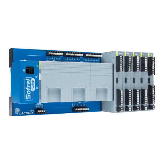
Page 11: I/O Expansion Modules
I/O Expansion modules I/O Expansion modules The RTU can be equipped with I/O expansion modules (10 modules max.) to expand its input-output capabilities. • The types of available I/O modules are: • 16DI • • 8AI-mA • 8AI-T° Example case with 2 I/O modules Disconnect button for each module. - Page 12 16 DI Expansion Module 16 DI Expansion Module Connection of DIs Example for 2 DIs: Possible applications: Pulse counters Duration counters Digital input loop: Normally closed Digital input loop: Normally open 1 pair for digital input no.2 1 pair for digital input no.1 1 shared for 4 digital inputs +24 V Technical specifications...
-
Page 13: 8Ai-Ma Expansion Module
8AI-mA Expansion Module 8AI-mA Expansion Module Connection of AIs (4-20mA) This type of AI is a ‘4-20mA Current’ measurement input. Only sensors delivering a current source free from any reference with respect to Ground and, in all cases, several sources having no common point between them, are directly compatible with our materials (‘floating’ output). -
Page 14: 8Ai-T Expansion Module
8AI-T Expansion module 8AI-T Expansion module Connection of AI (Temperature) modules • The ‘AI-T’ modules interface with the following temperature probes: • Pt 1000 type DIN43760 (IEC60751) • Ni 1000 type TCR5000 (Siemens probes) Ni 1000 type DIN43760 (IEC60751) Example for 2 AIs, ‘4-20mA’: 1 pair for ANA input no.2 1 pair for ANA input no.2 1 pair for ANA input no.1... -
Page 15: 4Do Or 8Do Expansion Module
4DO or 8DO Expansion module 4DO or 8DO Expansion module Connection of DOs One 12V / 24V AC/DC ’very low voltage’ voltage-relay type digital outputs: the DOs are compatible with 24 V relays and electrical cabinet indicator lights. By default, and following a total power cut (24 V and Battery), DOs are in their 'open' state (idle state = 0). However, the state of each DO is retained during product reinitialisation. - Page 16 8 AO Expansion module 8 AO Expansion module Connection of AOs An AO is an analogue output that generates a ‘0-10 V Voltage’ or ‘0-20 mA Current’ analogue signal. Each AO can be configured in voltage or current (parameter handled by the software). Example for 2 AO: 1 pair 1 pair for the ANA output no.2...
-
Page 17: Rs232 Communication Module
RS232 communication module RS232 communication module This module allows the RTU to communicate via RS232 link at an adjustable speed (with or without control signals) between 300 and 115,200 bits/s. The RS232 module is protected against short circuits, polarity inversion and accidental connection to voltage less than 24 V. -
Page 18: Rs485 Communication Module
RS485 communication module RS485 communication module This module allows the RTU to communicate via RS485 link with one or several devices connected to equipotential Grounds, as is often the case within a single building. A ‘bus’ network topology is required: no looping or star structure configurations. Any diversions from the main bus must be kept as short as possible (<... -
Page 19: Rs485I Communication Module
- Maximum length = 1200 metres (for greater lengths, use repeaters). For significant distances, install a 120 Ohm resistor Ω in parallel with the devices located at the 2 ends of the link (for more information, Contact the STC LACROIX Sofrel technical team). -
Page 20: Dl Communication Module
DL communication module: DL communication module: This module makes it possible for the remote terminal unit to communicate via Private link (in modulation) with one or several V23/V23R devices. • • Common • Private link Private link Connection as Private link: LS surge arrester LP link Example Multipoint Link:... -
Page 21: Edf Communication Module
EDF communication module EDF communication module This module makes it possible for the RTU to communicate over a ‘2 wire remote data’ link ( ERDF modulation at 1200 baud/50 KHz) reading data coming from an ERDF meter ( type). , or BLUE YELLOW GREEN... -
Page 22: Radio Rdrtu-2 Communication Module
RADIO RDRTU-2 communication module RADIO RDRTU-2 communication module (∗) The Remote Terminal Unit permits utilisation of a license-free RDRTU-2 radio modem at 869 MHz This modem radio is operable up to 500 mW to communicate with other remote equipment as MODBUS master or slave;... - Page 23 (expressed as a percentage over any period of time that a modem is allowed to transmit). Duty cycle limitation must be controlled by the terminal equipment connected to the modem. Contact LACROIX Sofrel’s Technical Department for your duty cycle calculations.
-
Page 24: Badge Communication Module
BADGE communication module BADGE communication module S4W allows the use of HID (contactless) badges for the People Identification, "Anti-Intrusion", and "Human Endangered" functions on monitored network sites. The + VDC power supply and pilot LED control are provided by the RTU (includes battery backup). -
Page 25: Power Balance
90 W (70°C MAX) The user must define the DIN Rail power supply model using the below table and summary: Maximum S4W article consumption S4W Compact and 3 COM modules 24 W I/O DI module 2.4 W I/O DO module 2.4 W... -
Page 26: Battery Life
Total (W) (Ethernet, GSM) 0.02 0.02 0.22 0.24 In the example given, S4W remote terminal unit consumes 4.6 W; the battery life is therefore 28.8 hours. (∗) Only available in countries where 869MHz frequency is allowed, check with country’s regulations.
Need help?
Do you have a question about the S4W and is the answer not in the manual?
Questions and answers