Table of Contents
Advertisement
22
23
24
25
28
29
30
31
34
35
36
37
Connect
Blue to N
(neutral)
Outer sleeve
firmly clamped
26
27
32
33
13 amp fuse approved
to BS1362
Brown L
(live)
Cable grip
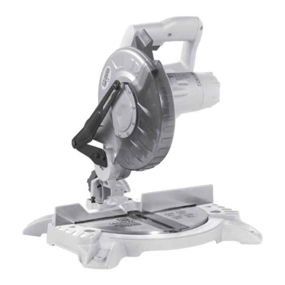
COMPOUND MITRE SAW
Performance Power Tools,
1 Hampshire Corporate Park, Chandlers Ford,
Eastleigh, Hants S053 3YX, U.K.
Technical Helpline 0845 300 2577
Caution: Carefully read this entire Instruction Manual before using this product
PMS Black U
PMS Warm Red U
SAFETY AND OPERATING MANUAL
Thank you for purchasing a Performance Power product. We are confident that this product will meet
and exceed your expectations of quality and reliability. Please take the time to carefully read this entire
instruction manual before using your new product, and take note of the basic safety precautions
contained herein.
210mm
NLE210MS
1 Hampshire Corporate Park, Chandlers Ford,
Code: NLE210MS
Date: 060608
Edition: 11
Op: BR
Performance Power Tools,
Eastleigh, Hants S053 3YX, U.K.
Technical Helpline 0845 300 2577
Advertisement
Table of Contents

Summary of Contents for Performance Power NLE210MS
- Page 1 SAFETY AND OPERATING MANUAL Thank you for purchasing a Performance Power product. We are confident that this product will meet and exceed your expectations of quality and reliability. Please take the time to carefully read this entire instruction manual before using your new product, and take note of the basic safety precautions contained herein.
- Page 3 Contents Parts list II - Technical data III - Safety instructions IV - Getting started Operation VI - Maintenance and repair VII - Guarantee I - Parts list II - Technical data 1. Saw arm Voltage:....... 230–240V ~ 50 Hz 2.
- Page 4 III - Safety instructions ADDITIONAL SAFETY RULES FOR MITRE SAWS GENERAL SAFETY INSTRUCTIONS e) Do not overreach. Keep proper footing and “live”. Switch off at the mains and remove the plug WARNING. Read all instructions. Failure to follow all balance at all times. This enables better control WARNINGS.
- Page 5 IV - Getting started BENCH MOUNTING The saw base has holes in each corner to facilitate bench mounting. ACCESSORIES Place the saw on a level, horizontal bench or The tool is supplied with the following work table using bolts (not supplied) and fix the accessories: saw to the bench using 4 bolts.
- Page 6 Place a set square against the table (12) and the against the fence, the board could break and flat part of the blade. jam the blade. SPINDLE LOCK BUTTON Place a square against the fence (11) and NOTE. Make sure that the square contacts the When cutting long pieces of timber, support the alongside the blade.
- Page 7 Place the workpiece flat on the table with one result in the table moving during the cut, Make sure that the electrical plug is removed Depress the spindle lock button (18) and edge securely against the fence (11). If the causing serious personal injury.
- Page 8 5. This guarantee is offered in addition to, and does not effect, your statutory rights, which PLUG REPLACEMENT may additionally enable you to cancel the If you need to replace the fitted plug then follow contract. The warranty is only valid within the the instructions below.
Need help?
Do you have a question about the NLE210MS and is the answer not in the manual?
Questions and answers
Hi have a NLE210MS 1400w can’t seem to pull it all the way down? The image shows the furthest I can pull down!
The Performance Power NLE210MS 1400W saw may not be pulled all the way down if the release knob (2) is not pulled. The release knob must be pulled to lift or lower the saw arm to its full height or position.
This answer is automatically generated
@Mr. Anderson please tell me or show me what the release knob looks like.
I need oder parts
You can order parts for the Performance Power NLE210MS by visiting Solent Tools' website. They have a selection of spare parts and accessories available for this model. If the part you need is not listed, you can email them and mention "PERFORMANCE POWER NLE210MS" to inquire about availability.
This answer is automatically generated