
Related Manuals for SEI 1800/48-2U-P-ACC


Summary of Contents for SEI 1800/48-2U-P-ACC
- Page 1 Installation and Operations Manual SEI 1800/48-2U-P-ACC DC-UPS SEI Incorporated 5115 Pegasus Court, Suite Q Frederick, Md 21704 Phone 301-694-9601 301-694-9608 Email Info@seipower.com http://www.seipower.com...
-
Page 2: Table Of Contents
TABLE OF CONTENTS Table of Contents ....................1 Description ......................2 Technical Specifications ..................3 Environmental Specifications ................3 Safety Information ..................... 4 Installation Instructions ..................5 Startup and Checkout………………………… ..........7 Theory of Operation................... 8 LED indicators ....................9 Alarm Contact Closures .................. -
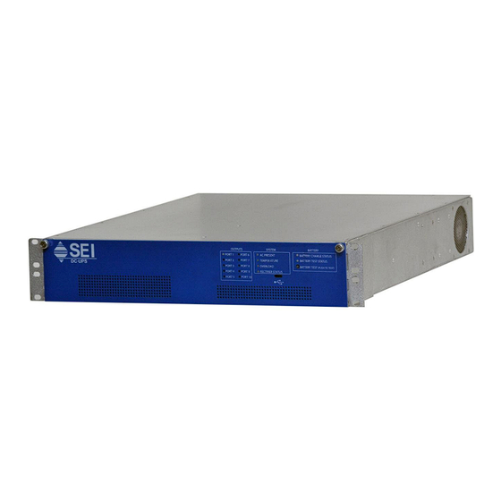
Page 3: Description
3 conductor cable. The Alarm Contact Closures are accessed via an RJ-45 jack on the left side of the rear of the unit. The SEI DC-UPS can be mounted on a 19-inch rack and occupies 2U (3.5 inches) of rack space. -
Page 4: Technical Specifications
TECHNICAL SPECIFICATIONS SEI 1800/48-2U-P-ACC AC Input Power Voltage 85-264 Vac Frequency 47-63 Hz Current (240 Vac input, 1800 W output) 9.0 Amps Typical 12.8 Amps Max (120 Vac input, 1800 W output) 18 Amps Typical 25.5 Amps Max DC Output Power Voltage 42.0 –... -
Page 5: Safety Information
SAFETY INFORMATION Always insure that the person assigned to the job can perform the job safely. Always lift all equipment properly. Always disconnect commercial power and remove the battery fuse before working on the unit. Always replace the batteries with batteries of the same type and style. DO NOT work on this equipment during an electrical storm. -
Page 6: Installation Instructions
If a claim for damages is to be made, it should be filed promptly with the transportation company. In addition, notify SEI within two days of delivery. SEI will advise the customer of any further procedures that may be required, including an RMA number in the event that the unit has to be returned to the factory for repair. - Page 7 20 lbs without the battery packs installed. It is recommended to mount the unit before installing the battery pack. 2. Rack Mounting - The SEI DC-UPS is designed to mount to a 19” rack using two racks screws per side. The mounting slots on each rack adapter are spaced in conformance with EIA standard RS-310-B.
-
Page 8: Startup And Checkout
+48Vdc Terminals 48rtn Terminals Output Port Fuse Figure 1 10/32 terminal Output Port 6. Attach to the ACC connector – Using a standard patch cord, connect to the DC- UPS Alarm Contact Closures via the RJ45 receptacle on the rear of the DC-UPS. 7. -
Page 9: Theory Of Operation
9601, for technical support. SYSTEM SHUTDOWN 1. The SEI 1800/48-2U-P-ACC DC-UPS is an uninterruptible power system. Therefore, removing the AC power feed to the unit will not shutdown the DC power distributed to the loads until the battery pack is full discharged. -
Page 10: Led Indicators
Rectifiers Three 600W rectifiers convert AC input power to regulated DC output power. The input of the rectifier are fused for protection... System Controller/LVD The System Controller has the following functions: Distribution of the DC power Battery charge voltage and current control and monitoring ... - Page 11 System Status Section: LED state Indication Solid Green Operating normally Slow Flash Red System Voltage below optimal battery charge voltage. (once per If Battery Charge Status LED is also flashing, unit is System second) operating on battery Voltage Fast Flash Red Battery almost depleted –...
-
Page 12: Alarm Contact Closures
Alarm Contact Closures The DC-UPS Alarm Contact Closures provide relay contacts to remotely monitor the status of the unit. The AC Fail relay indicates whether the unit is operating on AC power or on battery power. The function of the Battery Test Fail relay changes based on the status of the AC Fail relay. -
Page 13: Storage
STORAGE The DC-UPS batteries may be stored at temperatures of 25C or below for up to six months. The DC-UPS must be powered up with the battery packs installed for at least 48 hours every six months to maintain the batteries. For storage temperatures between 26C and 40C, the un-powered storage time must not exceed three months.
Need help?
Do you have a question about the 1800/48-2U-P-ACC and is the answer not in the manual?
Questions and answers