Table of Contents
Advertisement
Advertisement
Table of Contents

Related Manuals for Yeasn YPA-2100

Summary of Contents for Yeasn YPA-2100
- Page 1 YPA-2100 DIGITAL REFRACTOR User Manual Version: 1.0 Date: 20180521...
- Page 2 Information in promotional materials and packing boxes is subject to changes due to performance improvement without additional notice. Chongqing Yeasn Science & Technology Co., Ltd. reserves the rights to update the devices and materials. If you have any questions during using, please contact at our service hotline: (86-023) 62797666, we will be very happy to help you.
-
Page 3: Table Of Contents
Content 1. Specifications ....................... 1 1.1 Measurement range .................... 1 1.2 Host ........................1 1.2.1 Assistant lens ................... 1 1.2.2 Adjustment range ..................2 1.3 Power parameters ....................2 1.4 Dimensions ......................2 1.5 Weight ........................ - Page 4 5.4 Standard Optometry Procedure ................ 25 5.5 Binocular Functional Testing Method .............. 51 5.5.1 Crisscross matrix test (presbyopia) ............51 5.5.2 Cross test (heterophoria) ................ 51 5.5.3 Cross fixation vision test (heterophoria) ..........53 5.5.4 Cross ring test (heterophoria) ..............54 ...
- Page 5 13.Electrical Schematic Diagram ................... 82 14.Electromagnetic Compatibility .................. 83 ...
-
Page 6: Specifications
1. Specifications 1.1 Measurement range The measuring range conforms to the requirements in Table 1. Table 1 Vision tester measurement range Item Measuring range Spherical power -29.00D~+26.75D, Step size: 0.12D, 0.25D, 1D Cylindrical power -8.75D~+8.75D, Step size: 0.25D, 1D Cylindrical axis 0~180°, Step size: 1°, 5°... -
Page 7: Adjustment Range
1.2.2 Adjustment range 1)Adjustment range of pupil distance: 48mm~82mm 2)Forehead base can be adjusted continuously; the adjustment range should reach at least 14mm; 3)Adjustable range of near vision optometry distance: 150mm~400mm; 4)Corneal vertex marking: 12mm, 13.75mm, 16mm, 18mm and 20mm; 5)Horizontal adjustment: ±2.5°. - Page 8 may cause personal injury or device failure; ●Dedicated power adaptor configured for the device should be used: model MDS-060AAS15 B, Input 100V- 250V~1.5-0.75A 50Hz, Output 15V 4.0A. ●Make sure the input voltage is consistent with rated input voltage and the electric wire is correctly connected and well grounded;...
- Page 9 NOTE: This equipment has been tested and found to comply with the limits for a Class B digital device, pursuant to Part 15 of the FCC Rules. These limits are designed to provide reasonable protection against harmful interference in a residential installation. This equipment generates, uses and can radiate radio frequency energy and, if not installed and used in accordance with the instructions, may cause harmful interference to radio communications.
-
Page 10: Main Structure
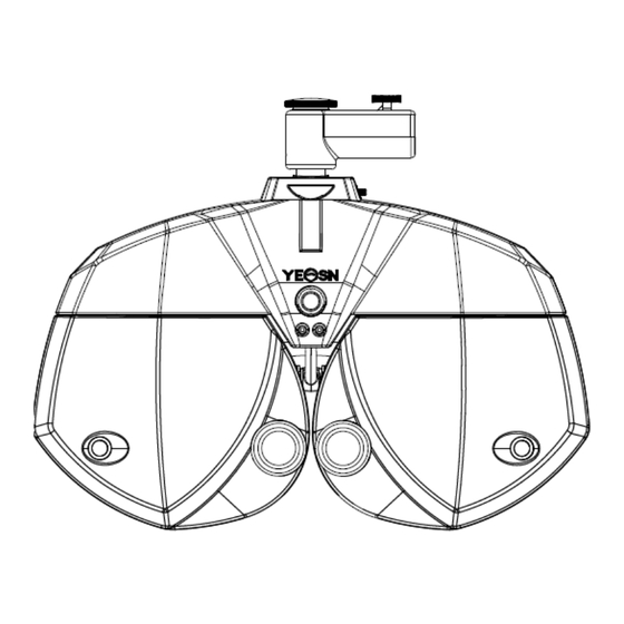
3. Main Structure 3.1 Host Front side (tester side) 1.Horizontal adjusting knob 9.Spirit level 2.Forehead baseplate indicator Forehead 3.Forehead baseplate knob 4.Near vision indicator 5. Cornea observation window 6.Testing window 7.Short-distance vision rod 8.Short-distance visual chart Back side (testee side) 11.Forehead baseplate 12.Cornea alignment window... - Page 11 10.Nose baseplate 1.Horizontal adjusting knob Adjust the horizontal level of the vision tester. 2.Forehead baseplate indicator Make sure the forehead of the testee contact the baseplate. The indicator is always on when the forehead doesn’t contact the baseplate; the indicator is off when the forehead contacts the baseplate. 3.Forehead baseplate knob Adjust the distance of the testee’s corneal vertex 4.Near vision indicator...
-
Page 12: Printing Base
12.Cornea aiming window Shows the alignment position of the testee’s corneal vertex. 3.2 Printing base Front Printing 1. Power switch Back 6. Power input interface Power output 4. R232 serial port 3. LAN Port 1.Power switch Turn on power switch; power indicator is lit up. 2.Printing bin Install printing papers. -
Page 13: Installation Method
5.Power output interface Connect to the power input interface of the host. 6.Power input interface Connect to the output interface of the power adapter. 4. Installation Method 4.1 Part List Digital refractor 1Set Printing bin 1Pcs Near Vision Chart 1Pcs Near Vision Rod 1Pcs Power adaptor... -
Page 14: Install Short-Distance Vision Rod
Knob Card tray Short-distance vision rod Short-distance visual chart 4.2.3 Install short-distance vision rod. Insert the vision rod into the installation hole in the vision tester host and screw the knob. Attention during installation: align the flute on the vision rod at the knob and keep the end of the vision rod close to the end of the installation hole in the vision tester host. -
Page 15: Install Printing Paper
4.2.5 Install printing paper Please refer to “Replace printing paper” (see 8.1). 4.2.6 Router settings Follow the setup guide provided by the router supplier to enter the router setup screen. Router parameters are set as follows: 1)LAN IP ADDRESS: 192.168.1.253 2) Router working mode: Access Point mode (AP) 3)SSID:yeasn_xxxxxx (xxxxxx is consistent with the nameplate serial number) 4)WPA-PSK/WPA2-PSK PSK password:yeasn2002... -
Page 16: Directions For Use
5. Directions for Use 5.1 Device Startup and Shutdown 5.1.1 Device startup 1)Insert the power plug into the socket. The power adaptor configured with the device is three-pin plug, please select suitable power socket. Note: please use dedicated power line configured with the device. 2)Start up the host first: press the power switch on the printing base, the power indicator is on. - Page 17 1. Date 2. Test number 3. Time Right testing window, input right eye data and select right eye as the dominant eye. 5. Measurement mode LD: Long-distance mode, SD: short-distance mode. Press “LD” or “SD” to shift between long-distance mode and short-distance mode. 6.
- Page 18 Left testing window, input left eye data and select left eye as the dominant eye. 8. Sighting mark area Select and display sighting marks. 9. Procedure Display current procedure. 10.S Spherical power input window Press S input window aside R to input the spherical power of right eye; press S input window aside L to input the spherical power of left eye.
- Page 19 16.VA VA Input box 17. Operation time Display the time spent from beginning to the end. 18. Del: data deletion Delete displaying data 19. Print: Printing is enabled when UNA, LM, AR, SUBJ or FINAL state requires measurement data. 20. Quick test Under non-prism mode, click this key to do near vision test.
- Page 20 :LCD visual chart is connected :LM is connected. :Print Box is connected. Remarks: All peripheral devices are connected automatically after powering on. If icons disappear, the peripheral devices are not well connected. 29. System Setting Click this key to set system 30.
-
Page 21: Assistant Lens Setup
5.2.2 Assistant lens setup 1. Press “Assistant lens” key to display assistant lens interface. 2. Press corresponding keys in the interface to. The selected assistant lens will be called in the testing window and return to testing interface automatically. Right assistant lens... - Page 22 Left assistant lens Keys description: Open testing window Baffle plate, shelter testing window Pinhole plate (hole diameter 1mm) Right eye: red optical filter, left eye: green optical filter Right eye: 45° linear polarized optical filter, left eye: 135° linear polarized optical filter...
-
Page 23: Pupil Distance Input
Binocular: circular polarized optical filter Right eye: fixed crisscross cylinder, left eye: fixed crisscross cylinder Right eye: horizontal Maddox rod, left eye: open testing window Right eye: open testing window, left eye: vertical Maddox rod Scieropia, press to change scieropia value. Retinoscopy lens, 1.50D and 2.0D optional Single-slit lens, press to change angle. - Page 24 Press “+” to enlarge PD, press “-” to reduce PD. 3. Press to exit PD input interface.
-
Page 25: System Parameter Setup
5.2.4 System parameter setup 1.Press to enter system parameter setup interface 2. Select needed parameter to change parameter setup. 3. When the setup is finished, press “exit” to return to testing interface. Detailed parameters are set as follows: AXIS step : 1°, 5°; Factory default: 5° Set step size for cylindrical axis, selectable between 1°and 5°. - Page 26 “No” means, carry out crisscross cylinder test. When the cylindrical power value C ≠ 0, carry out crisscross cylinder test in the organized sequence. Set this item “Off”, carry out crisscross cylinder test in the organized sequence. S.E.Fix(XC): on, off; factory default: on Select if adjust spherical power value, so as to keep refraction spherical equivalency during crisscross cylindrical test.
- Page 27 Div&Con Test: on, off; factory default: on Set if test the eyes’ collecting capability. Printing mode: all, except for AR; U.S.F, U, LM, AR, SUBJ and FINAL; factory default: all Set data content to be printed All: all data Except for AR: all data except for AR; U.S.F: uncased eye, subjective and final data.
- Page 28 Set if display test time. Set it “on”, all time spent from beginning to the end of the test displays. Set it “off”, operation time doesn’t display. SUBJ Startup: AR, LM; factory default: AR When inputting a set of AR or LM data, the vision tester automatically selects input data to carry out subjective optometry.
-
Page 29: Preparations Before Use
5.3 Preparations before Use 1)Turn on power switch, the device is automatically initialized. 2)Confirm the device is leveled. If the device is not leveled, rotate horizontal adjusting knob to keep the air bubble in the spirit level in the middle. Start up the combined tablet computer used and open the operation interface. -
Page 30: Standard Optometry Procedure
5.4 Standard Optometry Procedure Press “Program Reg”to start up standard optometry procedure . 1. Press to input AR (computer refractor) measurement data:... - Page 32 Press to test the uncased eye vision of the patient. The lens degree tested by the vision tester host is automatically 0. 1)Right eye test L testing window is baffled, test uncased right eye vision. Call in visual chart to test the best right eye vision. Input the tested right eye vision.
- Page 33 Call in visual chart to test the best binocular vision. Input the tested binocular vision. 3. Press to select if input degree with glasses. Select “No” to skip to step 6; select “Yes” to skip to step 4.
- Page 34 4. Press to input degree with glasses. Use LM to measure the degree of the glasses the patient wears and input measurement data.
- Page 35 5. Press to test the patient’s vision with glasses. Test the patient’s vision with glasses according to step 2 – the method to test the uncased eye vision of the patient.
- Page 36 6. Press to begin SUBJ subjective correction. Right eye scieropia. Baffle the left eye, change the cylindrical power of right eye to 0. Put on 0.5 sighting mark, and then gradually increase the positive spherical power until the 0.5 sighting mark becomes blurred.
- Page 37 7. Press to test the astigmatic axis with astigmatism disk. (1)Call in astigmatism disc sighting mark. Ask the patient: ●Do the definitions of all lines look the same? ●Which line looks especially distinct? If the answers are: ●The definitions of all lines look the same. No astigmatism, turn to step 9.
- Page 38 8.Press to test the astigmatic power with astigmatism disk. Take -0.25D cylinder as increment, gradually adjust the cylindrical power until the definitions of lines to all directions in the astigmatism disc are the same. 9. Press message prompts: skip crisscross cylinder test? When the cylindrical power is 0, message “skip crisscross cylinder test?”...
- Page 39 10. Press and call in 0.8 sighting mark, take -0.25D sphere as increment to gradually adjust the spherical power until the patient sees the sighting mark clearly.
- Page 40 11. Press to correct right eye spherical power with red and green sighting mark (first-time red and green test). Sphere +0.50D is automatically added to blur the vision. Call in red and green sighting marks. 1)Ask the patient: the letters in the red and green side of the sighting mark, which side looks more distinct? If the letter in the red side looks more distinct: press “-”...
- Page 41 12. Press to make the crisscross cylinder accurately test the astigmatic axis of the right eye. 1)Call in speckle sighting mark and ±0.25D crisscross cylinder. 2)Reverse side 1 and side 2 of the crisscross cylinder, ask the patient: which side is more distinct? When the side 1 is more distinct: enlarge the axis;...
- Page 42 4)Click key,shift to 0.5XC. 5)Click the key again, shift to automatic mode(Slit Prism).
- Page 43 13. Press to make the crisscross cylinder accurately test the astigmatic power of the right eye. 1)Reverse side 1 and side 2 of the crisscross cylinder, ask the patient: which side is more distinct? When the side 1 is more distinct: enlarge the astigmatic power; When the side 2 is more distinct: reduce the astigmatic power.
- Page 44 14. Press to correct right eye spherical power with red and green sighting mark (second-time red and green test). 1)Sphere +0.50D is automatically added to blur the vision. Call in red and green sighting marks. 2)Ask the patient: the letters in the red and green side of the sighting mark, which side looks more distinct? If the letter in the red side looks more distinct: press “-”...
- Page 45 15. Press to accurately adjust the spherical power to get the best vision of the right eye. Call in 1.0 sighting mark. Adjust spherical power, and ask the patient to keep eyes on the sighting mark. Ask the patient when the sighting mark looks more distinct. Take the lowest spherical power when the 1.0 sighting mark is clearly seen as the best vision of the right eye sphere.
- Page 46 16~25. Press to test the best vision of the left eye according to above step 6~15. So far, the SUBJ test for the left eye is finished.
- Page 47 26. Press to begin binocular equilibrium test (FINAL test) 1) Open R and L testing windows. Call in Speckle sighting mark, and 3△ face-down prism for right eye and 3△ face-up prism for left eye. 2)Ask the patients keep two eyes on the sighting mark and compare the definitions of upper and lower sighting marks.
- Page 48 27. Binocular best vision correction Reduce the spherical powers of two eyes by -1.00D synchronically, remove the prism in the binocular testing window, call in 1.0 sighting mark; enlarge the spherical powers of two eyes by -0.25D synchronically until the 1.0 sighting mark is clearly seen by two eyes.
- Page 49 28. Press to begin Worth 4 dots test. 1)Call in red optical filter in R testing window and green optical filter in L testing window, and Worth 4 dots sighting mark. 2)Confirm which points the patient can see clearly. 3)Input the Worth 4 dots testing result.
- Page 50 29. Press to begin stereopsis testing. 1)Call in red optical filter in R testing window and green optical filter in L testing window, and stereo sighting mark. 2)Confirm if the patient can see four straight lines with stereo clearly. 3)Input the stereoscopic parallax testing result.
- Page 51 30. Press message “near vision test?” prompts. Select “Yes”, skip to step 31. Select “No”, skip to step 34, the test is finished.
- Page 52 31. Input patient age 1)Call ±0.50D fixed crisscross prism in the binocular testing window. 2)Input the patient’s age. Shift long-distance degree to correction degree.
- Page 53 32. Press to test additional degree 1)Lower down the short-distance vision rod and place the visual chart in necessary working distance (generally 400mm). 2)Select the crisscross matrix sighting mark on the short-distance visual chart. 3)Ask the patient: the horizontal line or the vertical line, which is more distinct? Or the horizontal line and the vertical line look the same? If the horizontal line and the vertical line look the same: there is no need to carry out near vision test and change the additional degree.
- Page 54 33. Press to carry out near vision test. 1)Remove ±0.50D fixed crisscross cylinder. 2)Select short-distance visual chart to test the vision. 3)Make the patient see the sighting mark clearly to reach ideal vision value.
- Page 55 34. Press to finish the test.
-
Page 56: Binocular Functional Testing Method
5.5 Binocular Functional Testing Method 5.5.1 Crisscross matrix test (presbyopia) Test purpose: to test the spherical power. Test sighting mark: crisscross matric sighting mark Assistant lens: binocular ±0.50D fixed crisscross cylinder 1. Binocular distant vision test is finished, add distant vision degree in the testing window. 2. - Page 57 Sighting Diagnosis Correction mark shape No heterophoria Align eye position, no need for correction. Esophoria Increase BO prismatic power until it turns into a cross Exophoria Increase BI prismatic power until it turns into a cross Left Increase BU prismatic power in right eye and BD hyperphoria prismatic power in left eye until it turns into a cross Right...
-
Page 58: Cross Fixation Vision Test (Heterophoria)
5.5.3 Cross fixation vision test (heterophoria) Test purpose: to test heterophoria Test sighting mark: cross fixation sighting mark Assistant lens: Binocular rotatory prime Right eye red optical filter, left eye green optical filter (red and green cross fixation sighting mark) Binocular circular polarized optical filter (polarized cross fixation sighting mark) 1. -
Page 59: Cross Ring Test (Heterophoria)
according to right eye heperphpria until it turns into a cross. Correct the horizontal heterophoria according to Exophoria + left exophoria method and correct the vertical heterophoria eye hyperphoria according to right eye heperphpria until it turns into a cross. Note: When adding prismatic power, only add one eye’s prismatic power instead of two eyes’... -
Page 60: Horizontal Coincidence Test (Horizontal Image Inequality And Horizontal Heterophoria)
Note: When adding prismatic power, only add one eye’s prismatic power instead of two eyes’ prismatic powers. 5.5.5 Horizontal coincidence test (horizontal image inequality and horizontal heterophoria) Test purpose: to test horizontal image inequality and horizontal heterophoria Test sighting mark: horizontal coincidence sighting mark Assistant lens: Binocular rotatory prime Right eye red optical filter, left eye green optical filter (red and green horizontal coincidence sighting mark) -
Page 61: Horizontal Maddox Rod Test (Horizontal Heterphoria)
Test purpose: to test vertical image inequality and vertical heterophoria Test sighting mark: vertical coincidence sighting mark Assistant lens: Binocular rotatory prime Right eye red optical filter, left eye green optical filter (red and green vertical coincidence sighting mark) Binocular circular polarized optical filter (polarized vertical coincidence sighting mark) 1. -
Page 62: Horizontal Maddox Rod Test (Horizontal Heterphoria)
Assistant lens: right eye horizontal Maddox rod, left eye rotatory prism 1. Call in Maddox rod sighting mark. 2. Ask the patient about the sighting mark he sees and test according his answers. Sighting Diagnosis Correction mark shape No heterophoria Align eye position, no need for correction. -
Page 63: Clock Test (Rotatory Heterophoria)
5.5.9 Clock test (rotatory heterophoria) Test purpose: to test rotatory heterophoria Test sighting mark: clock sighting mark Assistant lens: Binocular rotatory prime Right eye red optical filter, left eye green optical filter (red and green clock sighting mark) Binocular circular polarized optical filter (polarized clock sighting mark) 1.Call in clock sighting mark. -
Page 64: Worth 4 Dot Test
5.5.10 Worth 4 dot test Test purpose: to test binocular fusion, suppression and dominant eye. Test sighting mark: Worth 4 dots sighting mark Assistant lens: Right eye red optical filter, left eye green optical filter 1. Call in Worth 4 dots sighting mark. 2. -
Page 65: Stereopsis
5.5.11 Stereopsis Test purpose: to test stereopsis Test sighting mark: stereo sighting mark Assistant lens: Right eye red optical filter, left eye green optical filter (red and green stereo sighting mark) Binocular circular polarized optical filter (polarized stereo sighting mark) 1. -
Page 66: Divergence Test
5.5.12 Divergence test Test purpose: to test the eyes’ congregation capability Test sighting mark: the column sighting marks in the visual chart Assistant lens: binocular rotatory prism Make sure the “Congregation and divergence test” parameter is set “On”. 1.Under prism mode,presss 2. -
Page 67: Congregation Test
3. Call in the sighting marks and display column sighting marks. 4. Increase BI prismatic power of two eyes until the sighting mark becomes obscure. Press the obscure icon, and it is highlighted, then save the prismatic power of the obscure point. 5. -
Page 68: Near -Point Congregation (Npc) Test
5.5.14 Near –point congregation (NPC) test No vision tester is needed in the test. If the patient wears glasses, do not take them off. Test purpose: to test split point Test sighting mark: cross fixation sighting mark, or nib that can easily cause diplopia. 1. -
Page 69: Near -Point Adjustment (Npa) Test
4. Move the nib gradually to approach to the patient’s eyes: when the patient sees the nib becomes two from one, stop moving the nib. 5. Measure the distance from the nib to the nose root of the patient. 6. Input the distance (in cm) into the input frame, the meter angle and prismatic power will be calculated automatically. -
Page 70: Positive-Relative Adjustment (Pra) Test
Confirmation before test: Set “SPH distant vision → near vision” to SPH+ADD. 1. Press , choose “Near Point”, NPC, NPA, NRA, PRA showing simultaneously, to shift to short-distance mode. Obscur Recover 2. Press “NPA” to open binocular testing window. 3. Place the visual chart in the distance of 40cm, make sure the patient see clearly the column sighting marks. -
Page 71: Customer Self-Programming
Obscur Recover 2. Press “NPA” to open binocular testing window. 3. Place the visual chart in the distance of 40cm, make sure the patient see clearly the row sighting marks. 4. Press “+” and “-” to gradually adjust the spherical power until the sighting mark becomes obscure. - Page 72 3. Program 1)A B C D are recommended vision test steps, users can also add or delete as needed.
- Page 73 2)E F G H are empty status, users can customize all the steps by themselves. 3)Keys Introduction Edit Key: Click it to enter program customizing interface Clear Key: Click it to delete this step.
- Page 74 Add Key: Click it to add one step automatically. 4)Click key to enter program customizing interface...
- Page 75 5)Headline can be input into the Program E box. According to user’s need, Editting the vision test program and then click OK key to save the setting.
-
Page 76: Run Customized Program
5.6.2 Run Customized Program 1)Go back to Measurement Interface. Click key to popup the program choice box 2)Choose “Program E”. - Page 77 3)Click key to start to run customized program. 5.7 Communication 5.7.1 Communication with Lensmeter CCQ-800 1) Use special communication cable to connect CCQ-800 to the R232 port of the print box. 2) Click LM key...
- Page 78 3) Click key to popup input box...
- Page 79 4) Use CCQ-800 lensmeter to test lens data and convey the date to YPA-2100 5)Click key . 6) Choose “No00001”.
- Page 80 7) Click key to complete data import.
-
Page 81: Troubleshooting
6.Troubleshooting In the event of device trouble, please check the device as per below chart to obtain guidance. If the trouble is not shot, please contact with Chongqing Yeasn Science & Technology Co., Ltd. Maintenance Department or the authorized dealer. -
Page 82: Cleaning And Protection
7.Cleaning and Protection Attention: Do not use any corrosive detergent to clean the device, so as not to damage the device surface. 7.1 Clean the forehead baseplate Clean the forehead baseplate before every optical test. 1)Take off the forehead baseplate Tilt the forehead baseplate forward as shown in right figure: drag in a certain direction and take off the baseplate. -
Page 83: Clean External Parts
Attention: Do not wipe the testing window with stiff cloth or paper; otherwise it may scratch the testing window glass. Attention: Wipe the testing window gently when cleaning it. Otherwise, it may scratch the testing window glass. 7.4 Clean external parts When the external parts, such as the enclosure or panel, get dirty, please wipe them gently with clean and soft cloth. -
Page 84: Maintenance And Care
8.Maintenance and Care 8.1 Replace printing papers When a red line occurs aside the printing paper, please stop using the printer and replace printing papers. Replacing steps are as follows: 1)Press the printing bin button to open the printer cover. Printing bin key Cover 2)Take out the left paper and put in the new printing paper. -
Page 85: Environmental Conditions And Service Life
Paper exit Press the print cover, be sure the "Printing bin key" is to the pop-up state, otherwise it will not be able to print. 8.2 Repairable and replaceable parts, such as printing base and power adapter, etc., provided by the company can only be used;... -
Page 86: Environmental Protection
10.Environmental Protection Please recycle or properly dispose of the used batteries and other wastes to protect the environment; please package the device at the end of life to the company, or handle it in accordance with local provisions related to environmental protection. 11.Manufacturer’s Responsibility The company is responsible for the safety, reliability and performance impact under below circumstances:... - Page 87 13.Electrical Schematic Diagram For further information and services, or any questions, please contact with the authorized dealer or manufacturer. We will be happy to help you.
- Page 88 14.Electromagnetic Compatibility Guidance and Manufacturer’s Declaration – Electromagnetic Emissions This device is intended for use in the electromagnetic environment specified below. The customer or the user of the devices should assure that the device is used in such an environment. Emissions test Compliance Electromagnetic environment - guidance RF emissions...
- Page 89 Guidance and Manufacturer’s Declaration – Electromagnetic Immunity This device is intended for use in the electromagnetic environment specified below. The customer or the user of the devices should assure that the device is used in such an environment. IEC60601 Electromagnetic environment - Immunity test Compliance level Test level...
- Page 90 Guidance and Manufacturer’s Declaration – Electromagnetic Immunity This device is intended for use in the electromagnetic environment specified below. The customer or the user of the devices should assure that the device is used in such an environment. IEC60601 Electromagnetic environment - Immunity test Compliance level Test level...
- Page 91 Recommended separation distances between portable and mobile RF communications equipment and the device These devices are intended for use in an environment in which radiated RF disturbances are controlled. The customer or the user of the device can help prevent electromagnetic interference by maintaining a minimum distance between portable and mobile RF communications equipment (transmitters) and the device as recommended below, according to the maximum output power of the communication equipment.
Need help?
Do you have a question about the YPA-2100 and is the answer not in the manual?
Questions and answers